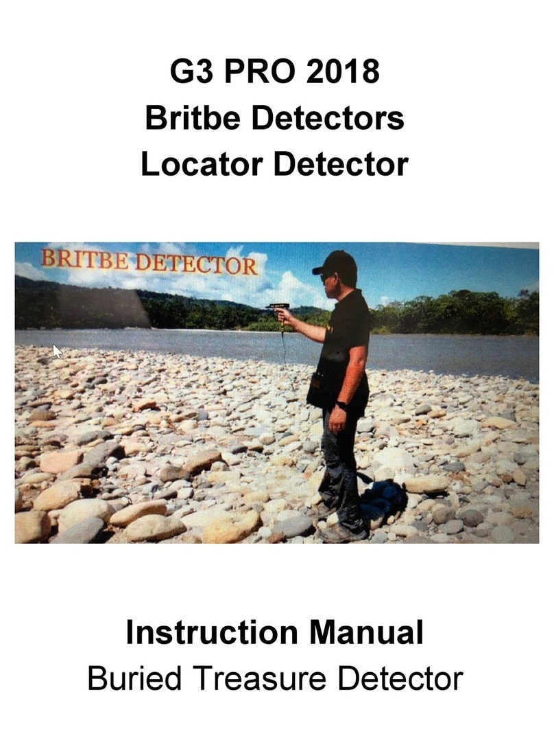
Dielectric MGD-2002 User manual

Model MGD-2002
Multi Gas Leak Detector
Instruction manual
IB-417 REV. I PART NO. 84671

User Safety Warnings
IMPORTANT: Before operating the device for the first time, read all
of the following safety guidelines. To prevent personal injury, property
damage, or damage to the detector, operate it only in accordance with
these safety guidelines.
• Do not operate the device if it has been damaged. Contact SPX
Radiodetection for advice.
• Do not allow any part of this device to come in contact with an ener-
gized high voltage source. Injury or death may result.
•Do not disassemble the device as it will void your warranty. Repairs
should only be performed by qualified factory service personnel.
•Do not allow the Detector to draw up water. Water will adversely
affect the device's operation and will cause internal damage. Water
found inside the unit will void your warranty.
•Take sensible precautions to prevent the ingress of moisture when
using the detector in rain, snow or other adverse conditions. Although
the detector is somewhat water resistant, it is not waterproof. Do not
allow water to accumulate on the detector faceplate, as it could mi-
grate into the electronics.
•Do not use the probe tip to dig in the soil, or use it in any manner
other than as directed in this manual.
•Although this device will operate with a low battery voltage, do not
operate the detector when the battery indicator displays 1/4 battery
or less. False readings may occur when operated under this condi-
tion. Refer to pages 7 through 9 for instructions on how to recharge or
replace the battery.
•When charging: This unit should be in an indoor dry location.
•Do Not plug the battery in backwards. Circuit board damage will
result
CAUTION - Refer to accompanying information
i

ii
Table of Contents
Section Description Page
User safety warnings i
Table of contents ii
1.0 Specifications 1
2.0 List of kit contents 2
3.0 Unpacking your New MGD-2002 3
4.0 Tracer gas 4
4.1 Helium vs Hydrogen as a tracer gas
4.2 Other Gasses the MGD-2002 will react too
5.0 Assembling the MGD-2002 for use 5
6.0 Operation of the MGD-2002 6
6.1 Overview
6.2 Humidity vs Accuracy
6.3 Moisture filter
6.4 Power supplies
6.5 Charging the battery
6.6 Charging the battery using the universal power supply
6.7 Charging the battery from a 12VDC auto adaptor
6.8 Replacing the battery
6.9 Button function and operation
6.10 Liquid crystal display (LCD)
6.11 Display status icon
7.0 Tracer gas leak locating for piping systems 14
8.0 Leak locating for pressurized cables 21
9.0 Serial port (if equiped) 33
10.0 Maintenance 33
11.0 Calibration 35
12.0 Frequently asked questions (FAQ) 36
13.0 Troubleshooting 39
14.0 Service information 40
Warranty Back cover

1.0 Specications
Dimensions: (LxWxD) 13.3in x 4.9in x 3.3in
(33.7cm x 12.3cm x 8.3cm)
Weight: (MGD-2002 only) 3.1 lbs (1400 grams)
(Shipping) 15.0 lbs (6800 grams)
Temperature Range: +40°F to +110°F
(+4°C to +43°C)
Humidity Range: 20% RH to 50% RH
Sensitivity: (Min) 25 PPM
(Max) 100% (1,000,000 PPM)
(Increment) 25 PPM (0 to 20,000 PPM)
0.1% (2% to 100%)
Tracer gasses: Helium (He) / Hydrogen (H)
Resolution: (Low range) +/- 25 PPM
(High Range) +/- 0.2 %
Response Time: 15 Seconds (approx.)
Audio Out: Pulse Width Modulation
LCD: 128 Bit X 64 Bit Dot Matrix
with long-life backlight
Battery: (Voltage) 7.2 VDC
(Type) Nickel Metal Hydride
(Weight) 383 grams
(Run Time) 6-8 Hours Continuous
(Charging Cycles) 300 - 500
(Charging Volts) 9.5 - 14 VDC @ 2A
Power Supply: (AC Input) 110-240V, 1.6A, 60/50Hz
(Charger) (DC Output) 12V, 4.0A
Pump Volume: 1.05 Liters/Min (approx.)
0.85 to 1.00 L/min
0.75 to 0.85 L/min
0.60 to 0.70 L/min
Compliance CE
1

1
2
3
49
10
11
5
6 7 8
2.0 List of kit contents
Description Part No.
1. MGD-2002 gas detector 79766
2. 12VDC Auto Adaptor charger 163-0005-01
3. Ground probe with Collection cup 90664
4. Spare moisture lter cartridge 83220
5. Sampling handle 83174
6. Needle probe 84165
7. Battery NiMH 82492
8. Sholder strap 300-0012-00
9. Backush connector 84972
10. 110-240 VAC universal AC charger 93642A
11. Carry case 84672
Optional equipment not included
• Headphones 882-0007
• European power cord 241-0003-00
• Serial port requires factory
installation
2

3.0 Unpacking your New MGD-2002.
3.1 Upon delivery
1) Open the shipping package and inspect the MGD-2002 for
any physical damage that may have been caused during
shipping. Keep the packing material in case you ever need to
return the device to SPX Radiodetection.
NOTE: The Manufacturer’s warranty does not cover damage
caused in transit. You must notify your carrier immediately for
any damage claims.
2) Position the device face down to open the battery compart-
ment door. Remove the battery to expose the device informa-
tion placard. (The serial number is located under the bar-
code.)
3) Connect the battery plug to the main logic board. Close the
battery compartment door and secure with the quarter turn
fastener.
NOTE: Connecting the battery incorrectly even for a second
will destroy the circuit board.
4) First, plug the universal power supply into a convenient AC
wall outlet then plug the other end into the device.
NOTE: To ensure optimum battery working life, charge battery
for 2 hours before operating the MGD-2002 detector for the
first time. See page 7 for battery charging instructions.
5) Check the moisture cartridge filter and ensure it is blue in
color. Refer to page 34 for filter changing instructions.
6) Before switching the device on, connect either the needle
probe or ground probe to the handle assembly and then con-
nect the handle assembly to the detector using the quick con-
nect fitting on the end of the black tubing. Refer to page 5.
3

4.0 Tracer Gas
4.1 Helium vs. Hydrogen as a tracer gas
The MGD-2002 is a Helium/Hydrogen detector calibrated to
detect “Helium”. However, it will indeed give readings if hydrogen
is present. As this detector is based on the thermal conductivity
of gasses and with Helium and Hydrogen being similar in this
regard the detector will not be able to tell the difference.
Helium is the preferred tracer gas. Helium is a noble gas and does
not react or combine with any other gas or substance. It is safe to
use in all types of leak locating at any concentration up to 100%.
Hydrogen is not generally present in higher quantities in
uncontrolled situations as it is very reactive and if in quantities
greater then 4% it is very ammable and even explosive. To use
it as a tracer gas you need to purchase it mixed to 4% or less
with the remainder being nitrogen. Thus, starting with an already
diluted tracer gas making it that much harder to nd as it dilutes
even further when you add it to the system being tested. (not
a problem when working with 100% helium) We certainly DO
NOT recommend Hydrogen be used as a tracer gas for these
reasons.
Note: It would take more then 20 tanks of 4% hydrogen mix to
equal the amount of traceable gas in one 100% helium tank.
Mixing the helium down to 4% is certainly an option and can be
done by adding compressed air to the system as it is being lled.
4.2 Other Gases the MGD-2002 will react to
When considering all other gasses there are some that would
normally present false reading when in high concentrations such
as CO, CO2 and Ozone (on a busy street) with helium detectors
using this above mentioned sensor type. However, we looked at
this situation based on our experience with older models of our
detectors and through the development of some patented lter
media combinations and custom software we have eliminated or
captured these gasses eliminating the majority of false readings.
Unfortunately methane even in very low concentrations can
cause the MGD-2002 to react but this is generally only seen
during certain environmental tests.
4

5.0 Assembling the MGD-2002 for use.
When assembling the device, refer to the List of Kit Contents on
page 2 of this manual.
1. Clip the black sampling tube quick-release connector of the
sampling handle (5) onto the connector on end of the MGD-
2002 detector (1).
2. Attach either the needle probe (6) or the Ground probe (3):
-
To attach the needle probe snap it into the quick connect
coupling of the sampling handle cap/adaptor.
-To attach the ground probe: Unscrew the cap/adaptor
from the sampling handle and screw the sampling handle
into the extendable ground probe (3). Do not overtighten
(Hand tight). Note: applying a small amount of silicone
based lubricant to the seal on both ends of the moisture
cartridge will improve its performance.
3. To extend the ground probe, press the lock button on the
sample probe and with it pressed, gently pull on the sample
collection cup. When the sample probe is at the required
length, release the lock button, ensuring it engages in a
locking position.
4. Turn the MGD-2002 on. The MGD-2002 will perform a self
check and zeroing routine (1 min approx). Youare now
ready to look for Helium/Hydrogen
5

6.0 Operation of the MGD-2002
6.1 Overview
The MGD-2002 gas detector is a portable leak-locating and
pinpointing device that can be used in a multitude of pressurized
systems to detect both hydrogen and helium when used as a
tracer gas . Because they are both lighter than air, hydrogen
and helium penetrate small leakage points rapidly. The gasses
permeate through the densest soils and pavements quickly
enabling the leak to be pinpointed easily with the detector.
6.2 Humidity vs Accuracy
The MGD will function correctly at high relative humidity (RH)
levels of 50% or greater, but its accuracy and sensitivity may be
reduced. Lower humidity is prefered.
6.3 Moisture filter
The replaceable moisture cartridge filter removes much of the
moisture from the sample and is designed to enable users to
quickly asses the filter daily life-span by visual inspection. A new
dry cartridge will be bright blue in color, and is shown on page
7. The moisture cartridge will turn pink as it removes moisture
from the air. As it changes color, the filter cartridge is still within
its useful life, but will degrade further to a clear white color if
continually used in high humidity conditions or if water is present.
To maintain optimum filter performance we recommend that you
change it or clear it of moisture when the color changes to light
pink.
The useful life of the filter depends upon the relative humidity
(%RH) of the working environment. For example, on an average
dry day, the %RH is roughly 20%, and in this case the filter should
last between 4-6 hours. If the relative humidity increases to 50%
RH, the single cartridge might last only 2-3 hours. If the humidity
increases to between 50-90% RH, the filter may only last one
hour.
With the MGD-2002 field replaceable system, filters can be
changed within seconds, or cleared and reused within minutes.
Refer to page 34 for instructions on how to change the filter.
6

The internal filtration material has a limited useful life, and S
PX
Radiodetection strongly recommends that the MGD is returned for
calibration once a year. During factory recalibration, the moisture
cartridges are cleared or replaced, and other filters have their filtra-
tion media changed. Refer to page 35 for a list of all the value-added
benefits that are included in a factory recalibration.
6.4 Power supplies
The MGD-2002 is powered by a replaceable, rechargeable nickel
metal hydride (NiMH) battery and comes supplied with a universal
AC/DC adapter, AC charging lead, and 12 volt DC charging lead
for use with a vehicle cigarette lighter socket.
6.5 Charging the battery
Charging from a completely dead battery will take approx 2 hours
and should last for approximately 6-8 hours of run time. While
charging, the battery will heat up and become warm. As the
sensor is sensitive to temperature changes it will be necessary
to wait approx 20 min for the battery temperature to return to
normal before using the device.
Note: It is not possible to use the MGD-2002 during battery
charging as the detection capability is automatically dis-
abled when the battery charger is plugged in.
Note:The battery is equipped with a temperature sensing
Spent Cartridge Dry Cartridge
7

element to ensure the battery will not overheat during the
charging cycle. If the ambient temperature is too high, bat-
tery charging may shut off prematurely. Ensure that the
MGD-2002 is charged away from any heat sources.
6.6 Charging the battery using the universal power
supply.
1. Plug the AC charging lead into the AC/DC adapter and plug
the other end into a standard power outlet
2. Plug the DC adapter lead into the charging connector located
on the right hand side of the MGD-2002
Note: When the charger is plugged into the MGD-2002 the LCD
will illuminate and display the battery recharging symbol.
Once charging is complete the symbol will change back to a plug
6.7 Charging the battery from a 12VDC auto adapter
1. Plug the auto adapter into the vehicle cigarette light
socket
2.Plug the output jack into the charging connector located
on the right hand side of the MGD-2002.
8

6.8 Replacing
the
battery
.
Caution - Do not mutilate, puncture, or dispose of bat-
teries by placing them in a fire. The batteries can burst or ex-
plode, releasing hazardous chemicals. Discard used batteries
in accordance with the battery manufacturer’s instructions
and your local regulations.
1. Lay the device face down on a flat surface and, using a flat
headed screwdriver, turn the battery cover retaining screw
1/4 of a turn counterclockwise and remove the battery-
housing-cover
2. Lift out the battery and gently pull up the battery connector
lead.
3. Before installing the new battery, attach the three pin con-
nector to the circuit board ensuring it is connected in the
correct orientation.
Note: Connecting the battery incorrectly even for a second
will destroy the circuit board.
4. Ensure that the battery is fitted in the correct position and
that it lies flat in the housing.
5. Install the battery cover taking care to avoid pinching the
wires. Tighten the retaining screw 1/4 turn clockwise.
9

6.9 Button functions and operation
The MGD-2002 features membrane buttons, and has a large multi-
function liquid crystal display (LCD). Each button has a raised
embossed edge that is designed to be felt by a user even when
wearing protective gloves. When they are pressed, the buttons
make a noticable “click” that is both felt and heard. The following is
a description of each key on the MGD:
CONTROL
(I/O) ON/OFF
BACKLIGHT
SOUND
BUTTON DESCRIPTION
The ON/OFF button supplies power to the
device. Once switched on, the device will
initialize, then conduct a 60 second power
on self test (POST).
The light button is used to switch the LCD
backlight on and off. By default the LCD
backlight is turned off to conserve battery
life. When the button is pressed, the back-
l i ght will illuminate and will remain on until
the button is pressed again, or the unit is
turned off.
The sound button is used to switch the
audio output of the internal speaker on and
off, allowing the operator to listen for the
detection of the tracer gas and not have
to watch the display. By default the audio
output is turned off.
10

PUMP SPEED
RESET
A/M
SAMPLE
Allows manual selection of various pump
speeds to increase accuracy of the sample
reading in situations with very small leaks. At
slower speeds the unit draws in less ambient
air with the sample.
The Reset button allows the unit to remain
powered up while clearing all the internal
logic circuitry. When the button is pressed,
the device goes through its zeroing routine to
determine a new baseline for future samples.
Using this button to reset the device is
preferred to turning the device off and back on
as it maintains power to the sensing elements,
thus maintaining sensor stability. Only press
this button in a zero tracer gas environment.
The Mode button controls what is being
displayed on the LCD. By default the unit is set
to automatic mode (A) and will constantly show
what the sensing elements have detected in
both concentration as well as time. If the unit
is placed in manual (M) mode, the device
will continue to draw in samples as normal.
However, when the sample button is pressed,
the LCD no longer shows time, but will only
show what the sensors are detecting at that
particular moment.
(Only available in manual mode) When the
sample button is pressed, one sample read-
ing is taken. The device calculates the time it
should take for the sample to reach the detec-
tor, takes the sample, and then displays the
result. The sample button must be pressed for
every sample needed.
11

6.10 Liquid Crystal Display (LCD)
The LCD is a near real-time display of the tracer gas
concentration the unit has detected. The refresh rate is slightly
greater than ten times every second.
After the unit is switched on. This screen
will remain displayed while the processor
conducts a power on self test, which lasts
for approximately 60 seconds.
The LCD displays the approaching zero
symbol upon successful completion of the
power on self test or when the unit has
just been reset. This display is showing
that the unit is setting a zero point of
reference.
The display upon successful completion
of the initial zeroing routine. This screen
will be displayed until the sensor elements
sense the presence of a tracer gas.
The real time graph is updated once per
second and shows 60 seconds of history.
12

6.11 Display status icons
There are five small icons shown at the bottom of the LCD screen.
The icon as well as its function is displayed below. The icons are
listed in the order in which they are displayed on the LCD, from left
to right.
NOTE: A function that has been turned off, will have an X
through its icon.
BATTERY STATUS
This icon gives a visual indicator of the relative life-
span remaining on the battery. When the battery
level drops below 1/4, a warning beep will sound.
The unit will automatically shut off when the empty
battery icon is shown
RECHARGE STATUS
This icon is either displayed, or crossed out. If
the unit is recharging, the icon will change to a
lightning bolt and back to a plug when charging is
complete.
MODE
Shows whether automatic (A) or manual (M) mode
is selected. The default is automatic.
SOUND STATUS
By default the speaker is disabled to conserve
battery power and the speaker symbol will initially
have an X through it. Pressing the speaker button
once removes the X and enables the audio out
circuitry.
PUMP SPEED
Pump speed can be adjusted for use in certain
sampling situation. Pressing repeatedly will slow
the pump until it returns to normal speed.
ICON
13

7.0 Tracer gas leak locating for piping systems
7.1 Assumptions:
• Youhave read and understand all safety information ex
pressed or implied in this MGD-2002 Instruction Manual as
well as your local safety codes and requirements.
• You have pinpointed the location of the system under
ground
• You have emptied the system of liquid
• You are able to inject helium at the low end and provide a
temporary vent at the other end to allow rapid filling.
• You can drill holes in the concrete every 3 feet (1meter) or so
• You are using 100% Helium or 4% Hydrogen as a tracer gas.
7.2 Applicability
This method can be used on any piping system, large or small
that can be emptied and filled with tracer gas. The gas will escape
from the system at the leak and be easily detectable at the surface
of the ground.
7.3 Effects on subscribers
With this method of leak locating the effects on the subscribers is
dependant on the type of system being checked. In the case of
a municipal water or gas system, subscribers should be notified
according to normal procedures. Additionally, on water systems
subscribers along this system should be instructed not to open a
tap during the leak detection process. There is no danger from the
gas but large amounts of tracer gas would be lost. Other system
types may not require any notification.
7.4 Preparing to leak locate
Leak test
Prior to leak locating you must actually determine you have a leak.
Performing a hydrostatic leak test on water systems will confirm
that you have a leak in the piping system and give you an idea
of how big the leak is. Pressurized air systems may show a sig-
nificant pressure drop or difficulty maintaining desired pressure.
Other systems may require other methods of leak determination.
14

7.5 Locate the system
Locate and mark the piping system path in the projected search
area, noting any recent construction or ground shifting in the area
that may have caused damage to the piping system. (There are
a large variety of pipe/cable locators available from SPX Radio-
detection. Please contact SPX Radiodetection sales or customer
service to purchase a locator for your application.)
7.6 Empty the system
In the case of a liquid filled system. Drain the liquid from the sys-
tem. It is not necessary to have the system completely dry but if
the leak is under liquid the tracer gas will need to push the liquid
out prior to exiting the system. Smaller piping such as heating sys-
tems (approx. 1 inch or smaller) may require using the tracer gas
or compressed air to push the liquid out.
Caution - Compressed Gas Contains Energy. Be
careful around pressurized systems: loose parts may
be ejected with high velocity if the pressurized system
bursts.
7.7 Filling the system with tracer gas
Attach the tracer gas. The key words from here on are “Don’t
Rush”. Saturating the ground or the underside of a concrete pad
with tracer gas will make it difficult to pinpoint the leak. The tracer
gas will filter through concrete and pavement “slowly” and this can
cause a plume to build up under the concrete and when it does
come through it will be in a much larger area. In cases where
there is substantial dense material such as concrete or pavement
over the piping system, it may be necessary to drill holes every
two to three feet over the pipe to improve the search results. (For
longer runs of piping with larger leaks under concrete or pavement
every 5-8 feet will narrow the search area.) These holes become
vents and allow for better pinpointing. Systems that are imbed-
ded in concrete will not require holes. However, it will require time
depending on the depth of the concrete.
Keep in mind that the tracer gas is lighter than air and wants to
rise. Start in the lowest point of the system as possible to allow
15

it to go up hill. Additionally, you will need to vent the other end
of the system until tracer gas can be detected at this vent. This
will ensure you that the tracer-gas has reached the leak. Once
detected at the vent, the vent can be closed and the system can
be pressurized with tracer gas. Approximately 3-5 PSI to start but
can be increased safely up to 10% of its normal working pressure
if the leak is not found. (The helium molecule is much smaller
than a water molecule and will exit a leak faster and easier than
water will.) The best approach is to start with lower pressures and
increase slowly. Remember: too much helium to start can make
a leak easy to find (large area) but hard to pinpoint. Also note that
helium will travel in the path of least resistance. (It will find the
easiest path it can, and that path may not be where you would
expect)
Caution - Never pressurize any system above its
working pressure.
7.8 How much tracer gas?
Calculate the volume
Area = π R^2 note Radius (R) in ft
Volume of system (cu ft) Vsys = Area (sqft X Length (ft)
Example: 500’ of 2” dia pipe
(3.142)(0.084)^2 = 0.022 sq ft
.022 * 500 = 11 cu ft
In this example 11cu ft is the total volume of air inside the pipe.
Note again, it is not necessary to get the pipe to 100% tracer gas
concentration. In most cases 5-10% is adequate for leak locating.
Now lets calculate the volume of air inside the pipe when we
increase the pressure to 5 PSIG. Building upon the previous ex-
ample:
Total cubic feet required at 5 PSIG
V@5PSIG = Vsys * ((14.7 + 5) / 14.7)
16

V@5PSIG = 11 * (19.7 / 14.7)
V@5PSIG = 14.74 cuft (with no leaks)
At 5 PSIG you would need only 1.47 Cu ft to reach 10% helium in
500ft of 2” dia. pipe with no leaks. In a small system such as this,
building the pressure using the tracer gas is perhaps the easi-
est way to increase and maintain the pressure while keeping the
tracer gas levels elevated.
A typical tracer gas tank contains 240 standard cubic feet of tracer
gas when full. At a constant flow rate of 30 SCFH, a full tank will
keep adding tracer gas to the system for approximately 8 hours.
240/30 = 8hr
Once the system has been filled and tracer gas is detected at the
vent. Close the vent and begin to build pressure. Continue to add
tracer gas to the system as it will keep the concentration elevated.
7.9 Very large piping system (12” or larger) or tanks
There are additional challenges in larger piping systems and
tanks. Getting enough tracer gas to saturate the system can be a
difficult one. This can be easily accomplished by emptying a full
tank of tracer gas into the system to get the concentration of gas
up rapidly. Then provide additional tracer gas along with com-
pressed air to build the desired pressure. Remember it is not nec-
essary to achieve 100% concentration in the system. That would
be a waste of tracer gas. 5-10% is certainly adequate for leak
locating as the MGD-2002 is capable of reading Helium as low as
25ppm (1%= 10,000ppm).
Another challenge for very large diameter pipe (> 2ft) and tanks
is that it may be necessary to provide some form of air movement
inside the piping system as the tracer gas will want to concentrate
near the top of the pipe. This can be accomplished using a fan
inside the piping to provide mixing.
17
Table of contents
