DIEX DXW3-30 Instruction Manual

1
DXW3-30
3 ELEMENTS -12/17/30 M
TRIBAND ANTENNA
ASSEMBLY/INSTALLATION

2
Thank you for purchasing our products. Be sure to read the manual, it is
important to know the product better to get the most out of it.
THE ANTENNA PARTS
-The boom has 2 parts.
-The larger “u” clamps are the supports for the elements.
-Take a good look at all the components and familiarize yourself with them.
-Aluminum tubes are identified with colors
-GREEN –DIRECTOR (D)
-RED –DRIVE (I)
-BLUE –REFLECTOR (R)
REQUIRED TOOLS
- Assembly
Few tools required for assembly are these:
-Spanners, 10/11 mm and 12/13 mm and set Phillips screwdrivers
-5 m tape measure
- Soldering iron
- Connection
The connection of the coaxial cable is of the “open” type, strip the coaxial
cable approximately 10 cm, separate the mesh from the center of the cable,
and solder the terminals that come with it.
Use self-amalgamating tape to protect the terminals and the cable from
rainwater.

3
CHOOSING THE BEST LOCATION
- The installation location is very important.
- Make a plan of all the actions you will take to install the antenna, if
necessary, ask for help from professionals.
- Choose the location looking for the greatest distance from trees, metal
structures, power lines, other antennas, distance from people, etc. The
proximity of these elements can reduce efficiency and make installation
difficult.
IMPORTANT
- Don't forget the security procedures.
ASSEMBLY
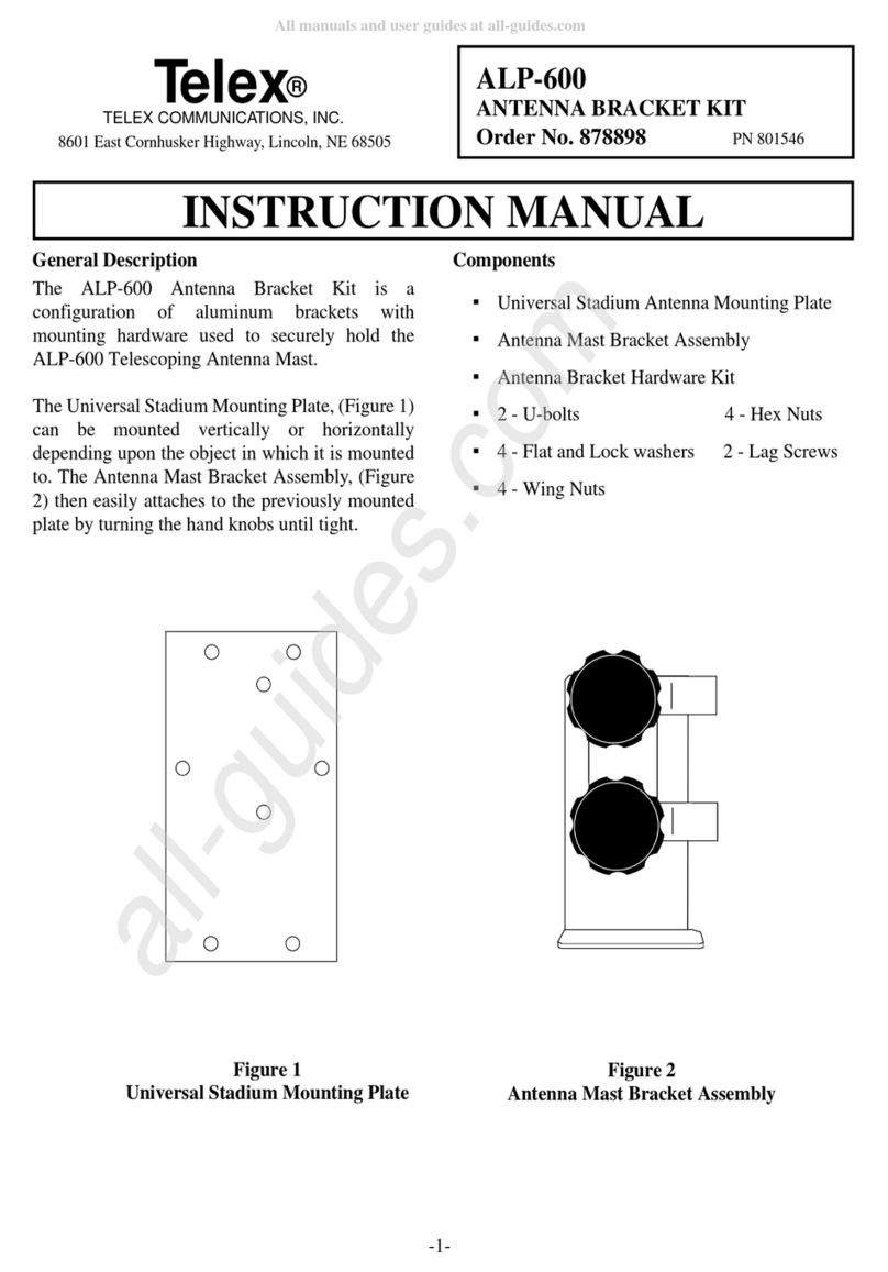
Assemble the DXW3-30 following the instructions as per the diagrams and
illustrations, assemble the boom first, then the elements, place the elements on
the boom, make the alignment, connect the coaxial, measurements and
adjustments and finally attach to the mast.
The cable connection is open type, see the shock detail in figure 2, it can be
done with the coaxial cable itself, strip 10 cm and separate the wires, solder
the terminals and leave only 20 cm of space until the start of the shock, they
are 12 turns in a diameter of 15cm, use a form for the turns to be well made
and parallel, DO NOT use cell cables as the dielectric is made of foam and can
deform when making the turns, thus altering the impedance, impairing the
functioning.
FIGURE 2
15cm
12
Turns
Weld the terminals

4
ADJUSTES
If there is a need for adjustments, make small adjustments to the drive element in 1 band at
a time, increasing if you want to lower the resonance frequency or decreasing if you want
to up the resonance frequency, as the adjustment of one band can interfere with the
adjustment of another band, always mark what you are doing and then put the same
measurement on the other side of the antenna.
Use a good meter that is reliable. Stay away from the antenna during measurements as your
body can cause an erroneous reading. A SWR of 2:1 or less is satisfactory and will not
decrease efficiency, if greater than 2:1, do a general check on measurements, position of
traps and connections.
The SWR check must be done with the antenna pointed upwards and preferably supported
on something insulating 50cm from the floor (it can be a wooden box, a chair, etc.
Measurements with the antenna close to the ground are wrong and will not hold up when
raising the antenna.
The ideal height for installation is ½ wave from the ground or buildings, if you do not have
this possibility, use ¼ wave or at least 1/8 wave, however the efficiency and bandwidth can
be changed.
Remember, biger antenna, lower frequency or smaller antenna, higher frequency.
Find the resonance point on the antenna (smallest SWR) and use this reminder to see if you
need to raise or lower the antenna to get the frequency you want as the center.
Raise the antenna and, if necessary, repeat the operations, the time invested in the
adjustments returns in quality of operation.
LIST OF COMPONENTS AND PARTS BY SECTION
REFLECTOR –(BLUE)
ITEM
DESCRIPTION
QTY
1
ALUMINUM PIPES 1 1/8” 1ª SECTION
01
2
ALUMINUM PIPES 1” 2ª SECTION
02
3
1ª TRAP (BLUE TAPE)
02
4
ALUMINUM PIPES 3/4” (FINAL)
02
GU1
“U” BOLT
01
APE
SUPPORT ELEMENT
01
EC
RUBBER COVER 3/4
02
A1
CLAMP
04
A2
CLAMP
04

5
DRIVE –(RED) Leave with 10cm of space between the elements.
ITEM
DESCRIPTION
QTY
5
ALUMINUM PIPES 1 1/8” 1ª SECTION
02
6
ALUMINUM PIPES 1” 2ª SECTION
02
7
1ª TRAP (RED TAPE)
02
7.1
2ª TRAP (RED TAPE)
02
8
ALUMINUM PIPES 3/4”(3ª SECTION)
02
8.1
ALUMINUM PIPES 5/8”(4ª SECTION)
02
8.2
ALUMINUM PIPES 1/2”(FINAL)
02
SP
DRIVE SUPPORT “U”
01
TB
INSULATOR PEAD
04
GU1
“U” BOLT WITH SUPPORT
01
A1
CLAMP
04
A2
CLAMP
04
EC
RUBBER COVER 3/4”
02
DIRECTOR (GREEN)
ITEM
DESCRIPTION
QTY
9
ALUMINUM PIPES 1 1/8” 1ª SECTION
01
10
ALUMINUM PIPES 1” 2ª SECTION
02
11
1ª TRAP (GREEN TAPE)
02
12
ALUMINUM PIPES 3/4” (FINAL)
02
GU1
“U” BOLT
01
APE
SUPPORT ELEMENT
01
EC
RUBBER COVER 3/4
02
A1
CLAMP
04
A2
CLAMP
08
BOOM
ITEM
DESCRIPTION
QTY
GA
ALUMINUM CONNECTION
01
GB
2”BOOM
02
CP
RUBBER COVER
02
P
SCREWS 1/4" X 2 1/2"
4

6
MAST SUPPORT
ITEM
DESCRIPTION
QTY
CPM
ALUMINUM PLATE
01
GBB-U51
“U” BOLT WITH LOW SUPPORT
04
BOOM ASSEMBLY
-Fit the tubes GB using the splice GA, secure the mast fixing plate CPM and after final
assembly look for the balance point which is close to from element driver.
GB GB
GA
CPM
CP CP
Fixing the element to the boom:

7
ASSEMBLYTHEANTENNA
- SEPARATE THE ITENS FOR EACH ELEMENTS
-ATTENCION: WATER OUTLET HOLES FACING DOWN
-The elements must be assembled and posicioned according to the drawing below.
1
9
1
9
2
10
2
10
3
11
3
11
4
12
4
12
EC
EC
EC
EC
245 cm 245 cm
215 cm
215 cm
80 cm 80 cm
71 cm
71 cm
28 cm
28 cm
28 cm
28 cm
235cm
185cm
216 CM 216 CM
20 CM 20 CM
10 CM
231 CM 231 CM
(24 MHZ) (24 MHZ)
(18 MHZ) (18 MHZ)
(10 MHZ) (10 MHZ)
5 5SP TBTBTB
TB 677.1 8 8.1 8.2
677.188.18.2
28 CM 28 CM
30,5CM 30,5CM
.
.

8
-Proceed with the measurement and permanently attach it to the mast and GOOD DX.
ATTENTION
If you want to disassemble the antenna, mark the elements again according to the manual,
to facilitate the reassembly.
SPECIFICATIONS
MODEL
DXW3-30
BAND
12/17/30 m
GAIN
8 DBI (12/17m) 2,4 DBI (30m)
F/B
25 dB / 0
2:1 SWR BANDWIDTH
+ 500 khz +150khz +80 khz
MAX. POWER
1.500 W PEP
BOOM
4,40m
> ELEMENT
10,60 m
TURNIG RADIUS
5,90m
MAST
1.¼” to 2”
WIND-LOAD
0,55 m2
WEIGHT
16 Kg
The contents of this manual are subject to change without notice.
WARRANTY
Diex antenna products are guaranteed for One year against manufacturing
defects, Diex may repair or replace parts or all of the product at its own
discretion within the warranty period. Damage caused by lightning, falling,
forces of nature, misuse, installation by an unqualified person, i.e., improper,
negligent or incorrect assembly is not covered by the warranty.
Products that undergo any adaptation or alteration or repairs by unauthorized
service automatically void the warranty.
Manual DXW3-30 fe
Table of contents
Other DIEX Antenna manuals
Popular Antenna manuals by other brands
KVH Industries
KVH Industries TracPhone V7-IP quick start guide
Winegard
Winegard Prostar 1000 PR-7010 Engineering specification

Globalstar
Globalstar Sat Fi2 quick start guide
ASC Signal
ASC Signal ES40K-1 Installation, operation and maintenance
Labgear
Labgear LAB350W user guide
Ebyte
Ebyte TX470-JZLW-15 user manual
