Visiosat NAUTIC 55cm User manual

INSTALLATION AND USER MANUAL
NAUTIC 55cm
Version 1.1 April 2012 since software version 1.1.8

page 2
Foreword
Congratulations on the purchase of your SMC55.
This manual will provide you with all the information you need about the installation,
use and maintenance of the system.
The SMC55 has been exclusively developed for use on inland waterways.
The system allows optimal enjoyment of the tremendous variety of radio and TV
programmes currently on offer via geostationary satellites, under way as well as in
port.
The use of high grade materials like stainless steel and durable plastics has been
maximised to ensure a long service life. Maintenance is also minimal, thanks to the
use of stepping motors and toothed belt transmissions.
WARNINGS AND REMARKS
All data is current at the time of going to press.
VISIOSAT shall not be liable in any
way for errors made during the drafting of this manual.
VISIOSAT retain the right to introduce any changes deemed necessary due to
product development and to introduce any necessary amendments to the installation,
to this user manual or to the products described in it, without prior notice.
Read this installation and user manual before using your SMC55 NAUTIC for the first
time. Carefully follow the instructions and take note of all warnings appearing on the
equipment and in this user manual.
Installation and service must be carried out exclusively by qualified persons.
There are no components within the installation which require service by the user.
Satisfy yourself that the wiring has been correctly connected before taking the
equipment into use.
Switch off and disconnect the power supply before carrying out any maintenance on
the system.
When opening the dome, bear in mind that that the dish antenna can move suddenly
and without warning unless the power supply is disconnected.
The dome must not be cleaned using a high pressure water jet. A soft damp cloth
with soap solution should be used instead.

page 3
In the event that the dome needs to be tilted due to the overall height of the vessel,
consult your dealer for input on cabling, power supply and further measures which
may be required.
For further information we would kindly request that you contact the specialist
supplier where you purchased the system, or contact us directly at:
VISIOSAT
ZI de Regourd
BP22
46001 Cahors Cedex 9
France
www.visiosat.com

page 4
Contents
1.1 SMC 55 NAUTIC packaging …………………………..5
1.2 Parts check-list ………………………......5
2. Installation instructions …………………………..6
2.1 Installation position identification …………………………..6
2.2 Installation of antenna dome and control unit …………………………..7
2.3 Electrical connection to antenna dome …………………………10
2.4 Electrical connection of control panel (MCM unit) ………………………....11
2.5 Assembly and dismantling of dome …………………………12
3.1 Functions of MCM unit control panel …………………………13
3.2 Operation of MCM unit …………………………14
3.3 Display of status of MCM unit …………………………15
3.4 Display of MCM unit error codes …………………………15
3.5 Explanation of Error Codes …………………………15
4.1 Menu structure …………………………16
4.2 Menu settings …………………………17
4.3 Satellite Selection …………………………17
4.4 Stand-by …………………………18
4.5 Installation Menu …………………………18
5. Technical data …………………………19
6. IP 55 certificate of protection …………………………20
7. Guarantee conditions …………………………21

page 5
1.1 SMC55 NAUTIC
The SMC 55 NAUTIC is packed in a strong plastic bag within a cardboard box
measuring 70 x 70 x 90 cm. The equipment can easily be lifted from the cardboard
box by two persons, using the strong plastic bag.
We request that you carry out the following checks before removing the packaging
: •The cardboard must not be deformed and must not display visible signs of
obvious and serious damage, such as rips in the box or dents caused by
impact.
•The VISIOSAT tape used to seal the packaging must remain intact.
1.2 Parts checklist
You should find the following components in the packaging:
Antenna dome (antenna unit in lower housing and dome)
Control unit for internal installation (MCM unit)
Manual.
Bag of components: - 2 no. 5 pole plugs
- 1 no. 2 pole plug
- 3 no. M8 x 45 mm stainless steel bolts
- 3 no. M8 stainless steel lock washers
- 4 no. ferrite clamps
- 3 no. sealing cap for cable throughput
Note. The bag of components is packaged together with the MCM unit.

page 6
2. Installation instructions
2.1 Determining installation position
Selection of location for installation of antenna dome
Various factors must be taken into account when selecting the correct installation
location for the antenna dome, these are summarised below:
•The ideal location will have a free line of sight in all directions.
•The antenna dome must be installed at the point where the three axes
intersect (roll, pitch and yaw motion).
•The external unit must be kept away from radar equipment as this can cause
interference; where no other location is possible it is recommended that the
antenna dome be installed a minimum of 1.5 metres below or above the radar
antenna.
•The substrate on which the antenna dome will be installed must be adequately
resilient and vibration free; in case of doubt we recommend that the substrate
should be reinforced with additional constructions.
Rule of thumb for reception of Astra 1 and 3:
An obstacle which is 3 metres away from the dome may be one
metre higher than the dome.
The rule of thumb assumes a minimal elevation of 20 degrees.
Table 1. Elevation of the dish versus geographical position for Astra 1 (19'2) and Astra 3 (23'5).

page 7
Selection of location for installation of control unit
The following instructions should be followed when selecting the location for the
control unit:
•The control unit may be installed in either a visible or a concealed location.
•We would however advise that the control unit should be installed in an easily
accessible location because of the potential need to install software updates.
•The control unit must not be installed in a damp or inadequately ventilated
space.
•Adequate space must be available at the rear of the control unit to allow
cables to be connected.
2.2 Installation of antenna dome and control unit
Once the location for the antenna dome has been decided the antenna can be
installed.
For a problem-free installation we recommend that you follow the procedure below:
•Check that the base plate where the antenna dome is to be mounted is level
and vibration free and can support a load of at least 22 kg.
•Before drilling fixing holes, check that there is sufficient room, taking account
of the dimensions of the antenna dome.
•When the ship is in a stable condition the surface should be parallel to the
water surface.
•The following drilling plan must be followed when securing the substructure of
the external unit, with account taken of the point where the cables emerge
from the antenna dome, and the maximal space occupied by the dome:
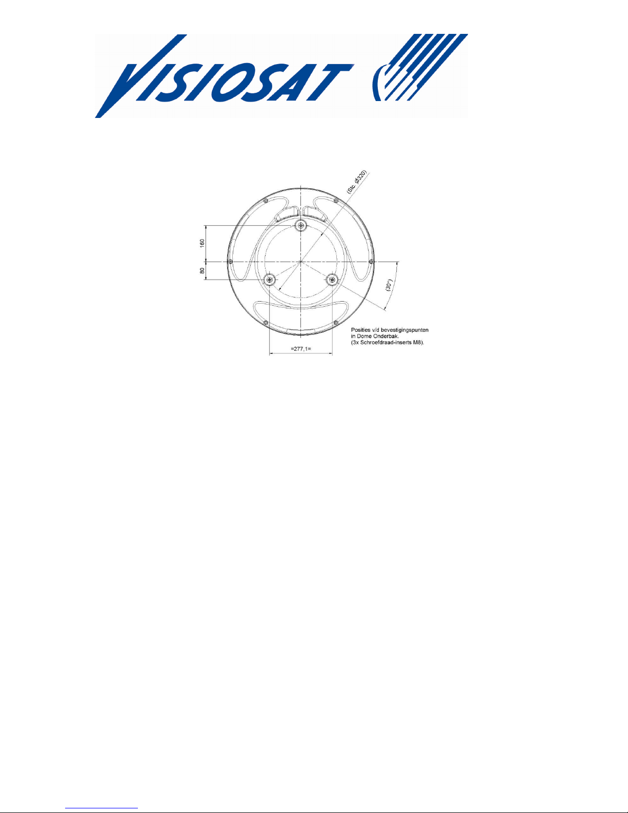
page 8
Where the SMC55 NAUTIC cannot be mounted from below using the M8 bolts and
lock washers supplied, it is possible to mount the drive from the inside.
NOTE! Remove the stainless steel screw thread holders from the drive feet with
an M8 bolt and nut before drilling out the holes.
The system can be secured from the inside if sufficiently long M8 stainless steel bolts
are used. With this installation method you will need to ensure that the galvanic
separation, provided by the plastic feet, remains intact.

page 9
Installation of control unit (MCM unit)
Once the location for the installation has been chosen the control unit can be
mounted. The MCM unit may be built in or attached to the mounting clamp provided.
If it is built in the MCM unit can be installed so that it is clamped in place.
If the unit is not appropriately sized for this, the 4 securing holes at the corners of the
front panel can be used for screw attachment.
Dimensions of control unit (MCM unit)

page 10
Electrical connection to antenna dome
The SMC 55 NAUTIC must be connected to a 24 volt DC power supply. The current
drawn when connected to a 24 Volt supply is around 3 amps.
The (brief) switch-on current is appreciably higher and is dependent among other
factors on the supply cable installed.
It is advisable to use a galvanically separated supply.
The supply terminal "+" should be connected to the plug clamp marked "24VDC" and
the "-" terminal to the 0V plug clamp.
The 5-pole plug is to be connected to the MCM unit.
Note: the system can be switched on and off using a switch which makes and
breaks the supply circuit. This method of switching off will ensure that the system
is not permanently connected to the satellite.
The SMC55 NAUTIC is equipped as standard for the connection of 4 tuners with
unlimited channel reception. It is possible to connect more tuners with the use of a
switchbox. More information can be provided by your supplier.

page 11
Electronics diagram with 4 receivers and option more connected.
•Remove the clamping rings from the cable fairleads and insert the cables
through these.
•The cable fairleads which are not used must be sealed off using the sealing
caps provided. If the unused fairleads are not sealed off water may penetrate
the antenna dome, seriously damaging the mechanical structure and the
electronic circuits.
•Connect the electrical cables to the appropriate 2 pole and 5 pole plugs and
connect the coax F-connectors. No chemical anti-oxidisation products or
silicone paste must be used with the coax F-connectors, as this can negatively
affect the quality of the radio frequency signal.
•Don't forget to install the Ferrite Clamps on the outgoing coax cables. This
must be located immediately behind the F connector on the coax cable(s).
•Check that the antenna unit can move freely and that there are no points of
friction.
•Having completed the installation, cover the antenna lower housing with the
dome.

page 12
2.4 Electrical connection control panel (MCM unit)
The MCM unit must be connected in the following way:
Rear MCM unit. Circuit diagram, antenna to MCM
1. 5 pole connector
2. The 2 pole connector is not used
3. RS 232 NMEA in and output
•Connect the 5 pole connector in accordance with the diagram
•The NMEA input and output are provided for service purposes and for future
developments

page 13
2.5 Assembly and dismantling of dome
The illustrations below show the assembly and dismantling of the dome.
NOTE! Extreme care must be taken to carry this out in dry weather conditions.
Dome assembly:
1 2 3 4
1 Place the 6 fixing clips in the recesses. Insert bolts in fixing clips by two turns.
The locking mechanism on the bolt allows the fixing clip to rotate at the same
time.
2 Check that all 6 fixing clips are able to move upwards after the dome has been
placed over the rubber seal. Check that the rubber is not doubled over.
3 Push the bolt and fixing clip upwards. When in upper position, rotate to the
right.
4 When the fixing clip clicks against the lower housing, tighten and maintain
rightward pressure on the allen key so that the clip does not come free from
the lower housing.
Dismantling dome:
1 2 3 4
1 Installed
2 Rotate to loosen until the fixing clip clicks against the other side of the lower
housing.
3 Rotate clip +/- 90˚ until it is above opening. (Visible from outside from the
position of the allen key).
4 Allow the bolt and clip to drop. The fixing is now loosened. It is also possible to
completely loosen the bolt until the clip falls into the lower housing. (6 no.)

page 14
3.1 Functions of MCM unit control panel
The MCM unit has 3 functions:
1 Monitoring; The status of the dish antenna can be seen from the display.
Various error codes can also be displayed.
(see Display of Error Codes and Status)
2 Control: Remote transmission of commands to the dish antenna
e.g. selection of satellite, stand-by function.
3 Maintenance: The replacement or updating of software.
1. Stand-by function (places the system in idle mode)
2. Down (move down through functions menu)
3. Up (move up through functions menu)
4. Enter (select in functions menu)
5. Escape (move back through functions menu)
6. USB port (for software updates)

page 15
3.2 Operation of MCM unit
Switching on
The SMC55 NAUTIC designed so that putting it into operation is very straightforward,
assuming that the system has been correctly installed.
Switch on your satellite receiver and TV set.
A 24 volt supply will be required when switching on the system, and it must be
switched out of stand-by mode if necessary.
N.B. The antenna will start up automatically when the 24V supply is switched on.
The following will then appear on the MCM screen:
System type: VISIOSAT
This message will disappear after a few seconds, and the system will then begin to
report its status.
Status: satellite (e.g. Astra 1)
Searching for Limit
This message indicates that the antenna system is in its start-up phase (the system
is searching for its reference points), a process that will take around 1 minute.
On completion of the start-up phase the system will begin its search for the specified
satellite.
After some time the SMC55 NAUTIC will lock onto the satellite and your TV set will
display the image received.
Status: satellite (e.g. Astra 1)
Tracking

page 16
Recommendation:
It is recommended that the system's power supply should be left switched on at all
times. With the system switched on the temperature of the electronics and the
internal climate in the dome is less subject to fluctuation, extending service life. If
necessary the Stand-by button can be used to switch the system off.

page 17
3.3 Display of status of MCM unit
The display indicates the status of the satellite to be tracked.
All status reports displayed are reports from the dome to the MCM unit.
Status : Searching for Limit : The system searches for its reference points
Searching for Sat : The system searches for the satellite
Tracking : The system tracks the satellite
Peaks : Optimising signal strength
Carry out tracking : The system positions itself
Stand-by : The system enters stand-by mode
3.4 Display of MCM unit error codes
Various texts will appear on the display to report errors
Error Codes:
E : No Limit.
E : No Signal.
E : Comm error.
E : Firmware not found.
E : Error during update
E : Usb disk not found
E : No Tuner.
3.5 Explanation of Error Codes
E : No Limit.
The system can not find its reference positions. Reset the system.
If "No Limit" appears again on the display, contact your dealer.
E : No Signal.
The system is not detecting any signal from the LNB. In this case the LNB may
be defective, or there is a poor connection with one or more of the coax cables
in the system.
E : Comm error.
There is no communication between the MCM unit and the dome. Check the
wiring between the MCM unit and the dome.
E : Firmware not found
No software is installed on the system. Reset the system.
Install software using USB stick.
page 18
E : Error during update
The software has not transferred correctly from the USB stick to the antenna
system. Reset the system and repeat the software procedure
E : USB disk not found
The USB stick has not been found or recognised.
E : No Tuner.
The tuner circuit is not detected by the motor circuit: contact your dealer.
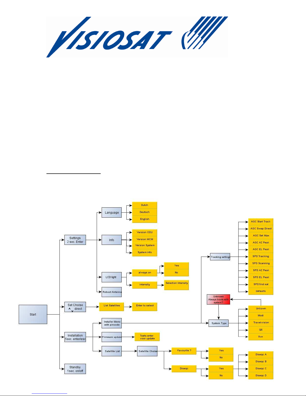
4.1 Menu structure
The menu allows a range of settings to be made.

page 19
Illustration of Menu structure
4.2 Menu settings
Press the enter key for 2 seconds
Language Choice of English, Dutch or German
(Press the up and down keys to navigate within the
list. Press the enter key to select).
Info Information on software version etc.
LCD Illumination Switch the background lighting on and off
Adjust light intensity
(Press the up and down keys to navigate within the
list. Press the enter key to select)
Restart antenna The antenna will restart
(Press enter key to restart antenna).
4.3 Satellite Selection
Press the up and down keys to navigate within the satellite favourites list.
Press the enter key to select satellite.
N.B! Satellites can be selected for the favourites list via the installer's menu.
Standard settings:
Satellite Position DiSEqC
(not supported with switchbox)
Astra 1 19.2 E A
Astra 3 23.5 E B
Astra 2 28.2 E C
Hotbird 13 E D
Satellites available for inclusion on the favourites list via the favourites list in the
installer's menu:
Satellite Position
Satellite Position
Astra 1 19,2 E Sirius 5 E
Astra 3 23,5 E Thor 1 W
Astra 2 28,2 E Atlanticbird 3 5 W
Hotbird 13 E Atlanticbird 2 8 W
Hellasat 2 39 E Atlanticbird 1 12,5 W
Eurobird 9a 9 E Telstar 12 15 W
Eutelsat W3A 7 E Hispasat 30 W

page 20
Note ! The LNB skew is optimized for reception of the red marked satellites. For
reception of the other satellites the LNB skew needs to be changed, this can only be
done by a certified Visiosat dealer. Please inform your dealer for further information.
4.4 Stand-by
Press the on/off key to place the system in stand-by mode.
4.5 Installation Menu
Press the enter and escape keys for 5 seconds to select menu
Firmware update This position is used to update antenna with new
software
(Press the enter key to select)
Insert the USB stick with the latest version of the
software
Press enter: the system will read in the software.
Wait until the antenna is fully re-started before
removing the USB stick! (If this is done prematurely
the antenna will give the error message: "USB disk
not found", and the software must be reinstalled!)
Installer mode Note! this is provided for installers only, and is
protected with a pin code.
Modifications may have major effects on the
operation of the system.
Tracking settings (correct by default)
System type (input type of the system)
Satellite in Fav List Satellite settings for favourites list with choice of
DiSEqC settings.
(Press the up and down keys to navigate within the
list. Press the enter key to select).
Having selected "yes" there is the option to modify
the DiSEqC
Table of contents
Popular Antenna manuals by other brands


TE Connectivity
TE Connectivity 2118326-1 quick start guide

Andrew
Andrew OM24SNG-RC Operation and maintenance

Shakespeare Electronic
Shakespeare Electronic PHASE III 6235-R manual

Galleon
Galleon TS-500-GPS Installation and configuration manual

PCTEL
PCTEL VENU MPMI2458 Installation notes

Andrew
Andrew DB201 Series installation instructions


