Digi-Sense 20250-64 User manual

User Manual
THE STANDARD IN PRECISION MEASUREMENT
Heavy-Duty Autoranging
Digital Multimeter
with Bluetooth®Mobile App and
NIST-Traceable Calibration
Model 20250-64
1065DGMAN_20250-64_Rev1.indd 1 07/02/2019 11:23:02 AM

2
Introduction
The Digi-Sense Heavy-Duty Autoranging Digital Multimeter
with Bluetooth® Connectivity (model 20250-64) allows you to
transmit data directly to your Android™or iOS®device using our
free D/S Meter app. Now you can view data at a safe distance
from potentially hazardous parameters or even use your smart
device as a real-time secondary display for checking measure-
ments, eliminating the need to write down readings on paper. The
results are automatically stored in the app with a date-and-time
stamp and can be saved as a CSV file and emailed for future
reference, manipulation, or analysis to help determine trends and
conditions over a long period of time. You can also use the app to
attach photos and notes to the records creating a clear reference
point for your work—ideal for record keeping at large sites.
Setup is simple. Download the free D/S Meter app to your Android
or iOS device. Place the multimeter in Bluetooth mode and open the
app on your smart device. The meter will be sensed by your device
and be listed as an available source that you can select. Once
selected, the data sensed by the meter is displayed on your device
and some of the instrument functions can be accessed. A full
description of its operation is available for download in the app.
The Heavy-Duty Digital Autoranging Multimeter measures
AC/DC voltage, AC/DC current, resistance, frequency (electrical &
electronic), capacitance, diode test, and continuity. The meter also
offers True RMS for more accurate current readings, temperature
measurement with a type K thermocouple, and analog bar graph for
viewing trends. Rugged IP67-rated waterproof design withstands
heavy-duty use. This instrument is fully tested and calibrated to
NIST-traceable standards for reliable measurements right out of the
box, saving you time and money. Proper use and care will provide
many years of reliable service.
1065DGMAN_20250-64_Rev1.indd 2 07/02/2019 11:23:02 AM

3
Safety
International Safety Symbols
This symbol, adjacent to another symbol or terminal, indicates
the user must refer to the manual for more information.
This WARNING symbol indicates a potentially hazardous
situation, which if not avoided, could result in death or
serious injury.
CAUTION symbol indicates a potentially hazardous situa-
tion, which if not avoided, may result in product damage.
This symbol advises the user that the terminal(s) so
marked must not be connected to a circuit point at which
the voltage with respect to earth ground exceeds (in this
case)1000VAC or 1000VDC.
This symbol adjacent to one or more terminals identifies
them as being associated with ranges that may, in normal
use, be subjected to particularly hazardous voltages. For
maximum safety, the meter and its test leads should not
be handled when these terminals are energized.
This symbol indicates that a device is protected through-
out by double insulation or reinforced insulation.
MAX
WARNING
CAUTION
1065DGMAN_20250-64_Rev1.indd 3 07/02/2019 11:23:03 AM
4
Safety Instructions
This meter has been designed for safe use but must be operated
with caution. The rules listed below must be carefully followed
for safe operation.
1. NEVER apply voltage or current to the meter that exceeds the
specified maximum:
2. USE EXTREME CAUTION when working with high voltages.
3. DO NOT measure voltage if the voltage on the “COM” input
jack exceeds 1000V above earth ground.
4. NEVER connect the meter leads across a voltage source while
the function switch is in the current, resistance, CAP, or diode
mode. Doing so can damage the meter.
5. ALWAYS discharge filter capacitors in power supplies and
disconnect the power when making resistance or diode tests.
6. ALWAYS turn off the power and disconnect the test leads
before opening the covers to replace the fuse or batteries.
7. NEVER operate the meter unless the back cover and the battery
and fuse covers are in place and fastened securely.
8. If the equipment is used in a manner not specified by the
manufacturer, the protection provided by the equipment may
be impaired.
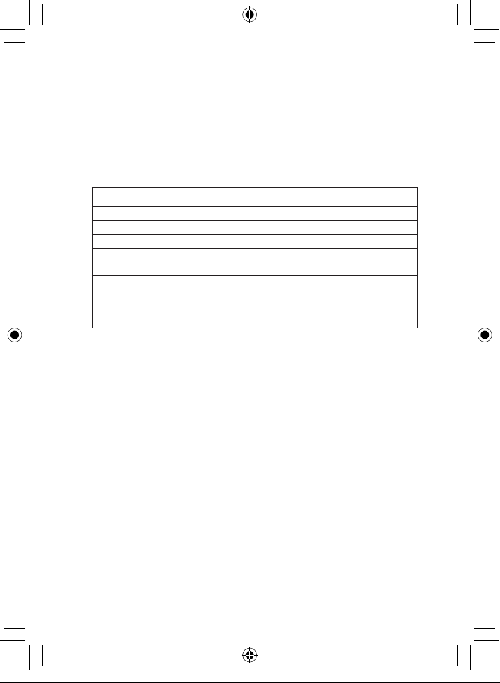
Input Protection Limits
Function Maximum Input
V DC or V AC 1000 VDC/1000 VAC RMS
mA AC/DC 500 mA 1000 V fast acting fuse
A AC/DC 10 A 1000 V fast-acting fuse (10A for 30 seconds
max every 15 minutes)
Frequency, Resistance,
CAP, Diode Test, Continuity,
Temperature, Duty Cycle 250 VDC/AC RMS
Surge Protection: 8 kV peak per IEC 61010
1065DGMAN_20250-64_Rev1.indd 4 07/02/2019 11:23:03 AM

5
Unpacking
Check individual parts against the list of items below.
If anything is missing or damaged, please contact your
instrument supplier immediately.
1. Meter
2. Test leads
3. One type K temperature probe
4. One 9 V battery
5. Carrying case
6. User manual
7. NIST-traceable calibration report with data
Key Features
• Bluetooth interface
• User-friendly mobile app
• 4000 display count
• True RMS readings
• Electronic overload protection
• Autoranging with auto power-off
• Data Hold function
• Rugged IP67-rated double-molded housing
1065DGMAN_20250-64_Rev1.indd 5 07/02/2019 11:23:03 AM
6
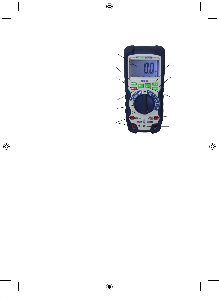
Meter Description
1. 4000 counts LCD
2. MAX/MIN button
3. RANGE button
4. MODE button
5. Rotary function switch
6. mA, µA and 10 A
input jacks
7. COM input jack
8. Positive input jack
9. Hz and % button
10. HOLD and Backlight button
11. RELATIVE and Bluetooth button
Note: Tilt stand and battery compartment are on rear of unit.
1
3
4
2
5
6
9
10
11
8
7
1065DGMAN_20250-64_Rev1.indd 6 07/02/2019 11:23:03 AM

7
Symbols and Annunciators
Auto power-off
•)))Continuity
Diode test
Battery status
µmicro (10–6)
mmilli (10–3)
A Amps
kkilo (103)
Mmega (106)
ΩOhms
Hz Hertz (frequency)
V Volts
% Percent (duty ratio)
REL Relative
AC Alternating current
AUTO Autoranging
DC Direct current
HOLD Display hold
MAX Maximum
MIN Minimum
hFE Reserved
Bluetooth
°F Degrees Fahrenheit
°C Degrees Centigrade
1065DGMAN_20250-64_Rev1.indd 7 07/02/2019 11:23:03 AM
8
Setup and Operation
WARNING: Risk of electrocution. High-voltage circuits, both
AC and DC, are very dangerous and should be measured
with great care.
1. ALWAYS turn the rotary function switch to the OFF position
when the meter is not in use.
2. If “OL” appears in the display during a measurement, the
value exceeds the range you have selected. Change to a
higher range.
DC Voltage Measurements
CAUTION: Do not measure DC voltages if a motor on the circuit
is being switched ON or OFF. Large voltage surges may occur
that can damage the meter.
1. Set the rotary function switch to the green VDC position.
2. Insert the black test lead banana plug into the negative
COM jack and the red test lead banana plug into the
positive Vjack.
3. Touch the black test probe tip to the negative side of the
circuit and touch the red test probe tip to the positive side
of the circuit.
4. Read the voltage in the display.
1065DGMAN_20250-64_Rev1.indd 8 07/02/2019 11:23:03 AM
9
AC Voltage (Frequency, Duty Cycle) Measurements
WARNING: Risk of Electrocution. The probe tips may not be
long enough to contact the live par ts inside some 240V outlets
for appliances because the contacts are recessed deep in the
outlets. As a result, the reading may show 0 volts when the
outlet actually has voltage on it. Make sure the probe tips are
touching the metal contacts inside the outlet before assuming
that no voltage is present.
CAUTION: Do not measure AC voltages if a motor on the
circuit is being switched ON or OFF. Large voltage surges may
occur that can damage the meter.
1. Set the rotary function switch to the green VAC/Hz/% position.
2. Insert the black test lead banana plug into the negative
COM jack and the red test lead banana plug into the
positive Vjack.
3. Touch the black test probe tip to the neutral side of the
circuit and touch the red test probe tip to the “hot” side
of the circuit.
4. Read the voltage in the display.
5. Press the Hz/% button to indicate “Hz”.
6. Read the frequency in the display.
7. Press the Hz/% button again to indicate “%”.
8. Read the percent of duty cycle in the display.
1065DGMAN_20250-64_Rev1.indd 9 07/02/2019 11:23:03 AM
10
DC Current Measurements
CAUTION: Do not make 10 A current measurements for longer
than 30 seconds. Exceeding 30 seconds may cause damage to
the meter and/or the test.
1. Insert the black test lead banana plug into the negative
COM jack.
2. For current measurements up to 4000 µA DC, set the rotary
function switch to the yellow µAposition and insert the red
test lead banana plug into the µA/mA jack.
3. For current measurements up to 400 mA DC, set the rotary
function switch to the yellow mA position and insert the red
test lead banana plug into the µA/mA jack.
4. For current measurements up to 10 A DC, set the rotary
function switch to the yellow 10A/Hz/% position and insert
the red test lead banana plug into the 10A jack.
5. Press MODE button to indicate “DC” on the display.
6. Remove power from the circuit under test, then open up the
circuit at the point where you wish to measure current.
7. Touch the black test probe tip to the negative side of the circuit
and touch the red test probe tip to the positive side of the circuit.
8. Apply power to the circuit.
9. Read the current in the display.
1065DGMAN_20250-64_Rev1.indd 10 07/02/2019 11:23:03 AM

11
AC Current (Frequency, Duty Cycle) Measurements
CAUTION: Do not make 10 A current measurements for longer
than 30 seconds. Exceeding 30 seconds may cause damage to
the meter and/or the test.
1. Insert the black test lead banana plug into the
negative COM jack.
2. For current measurements up to 4000 µA AC, set the
rotary function switch to the yellow µAposition and insert
the red test lead banana plug into the µA/mA jack.
3. For current measurements up to 400 mA AC, set the rotary
function switch to the yellow mA position and insert the
red test lead banana plug into the µA/mA jack.
4. For current measurements up to 10 A AC, set the rotary
function switch to the yellow 10A/Hz/% position and insert
the red test lead banana plug into the 10A jack.
5. Press the MODE button to indicate “AC” on the display.
6. Remove power from the circuit under test, then open
at the point where you wish to measure current.
7. Touch the black test probe tip to the neutral side of the
circuit and touch the red test probe tip to the “hot” side
of the circuit.
8. Apply power to the circuit.
9. Read the current in the display.
10. Press the Hz/% button to indicate “Hz”.
11. Read the frequency in the display.
12. Press the Hz/% button again to indicate “%”.
13. Read the percent of duty cycle in the display.
14. Press the Hz/% button to return to current measurement.
1065DGMAN_20250-64_Rev1.indd 11 07/02/2019 11:23:03 AM
12
Resistance Measurements
WARNING: To avoid electric shock, disconnect power to the
unit under test and discharge all capacitors before taking any
resistance measurements. Remove the batteries and unplug
the line cords.
1. Set the rotary function switch to the green Ω
•)))position.
2. Insert the black test lead banana plug into the negative COM
jack and the red test lead banana plug into the positive Ωjack.
3. Press the MODE button to indicate “Ω” on the display.
4. Touch the test probe tips across the circuit or part under test.
It is best to disconnect one side of the part under test so the
rest of the circuit will not interfere with the resistance reading.
5. Read the resistance in the display.
Continuity Check
WARNING: To avoid electric shock, never measure continuity on
circuits or wires that have voltage on them.
1. Set the rotary function switch to the green Ω
•)))position.
2. Insert the black test lead banana plug into the negative COM
jack and the red test lead banana plug into the positive Ωjack.
3. Press the MODE button to indicate “•)))” and “Ω” on
the display.
4. Touch the test probe tips to the circuit or wire you wish
to check.
5. If the resistance is less than approximately 35 Ω, the audible
signal will sound. If the circuit is open, the display will
indicate “OL”.
1065DGMAN_20250-64_Rev1.indd 12 07/02/2019 11:23:03 AM

13
Diode Test
1. Set the rotary function switch to the green Ω
•)))position.
2. Insert the black test lead banana plug into the negative COM
jack and the red test lead banana plug into the positive Vjack.
3. Press the MODE button to indicate “
” and “V” on
the display.
4. Touch the test probes to the diode under test. Forward volt-
age will typically indicate 0.400 to 0.700 V. Reverse voltage
will indicate “OL”. Shorted devices will indicate near 0 V and
an open device will indicate “OL” in both polarities.
Frequency/Duty Cycle Measurements (Electronic)
1. Set rotary function switch to the green Hz/% position.
2. Press the Hz/% button to indicate “Hz” on the display.
3. Insert the black test lead banana plug into the negative
COM jack and the red test lead banana plug into the positive
Hz jack.
4. Touch the test probes to the circuit under test.
5. Read the frequency on the display.
6. Press the Hz/% button again to indicate “%” on the display.
7. Read the percent of duty cycle on the display.
1065DGMAN_20250-64_Rev1.indd 13 07/02/2019 11:23:03 AM

14
Temperature Measurements
1. Set the rotary function switch to the green Temp position.
2. Insert the temperature probe into the input jacks, making sure
to observe the correct polarity.
3. Press the MODE button to indicate °F or °C.
4. Touch the temperature probe head to the part whose tempera-
ture you wish to measure. Keep the probe touching the part
under test until the reading stabilizes (about 30 seconds).
5. Read the temperature in the display.
Note: Temperature probe is fitted with a type K mini connector.
Mini connector to banana connector adapter is supplied for
connection to the input banana jacks.
Autoranging/Manual Range Selection
When the meter is first turned on, it automatically goes into
autoranging mode. This automatically selects the best range for the
measurements being made and is generally the best mode for most
measurements. For measurement situations requiring that a range
be manually selected, perform the following:
1. Press the RANGE key. The “AUTO” display indicator will
turn off.
2. Press the RANGE key to step through the available ranges
until you select the range you want.
3. To exit the manual ranging mode and return to autoranging
mode, press and hold the RANGE key for 2 seconds.
Note: Manual ranging does not apply for the Frequency functions.
MAX/MIN Function
Note: When using the MAX/MIN function in autoranging mode,
the meter will “lock” into the range that is displayed on the LCD
when MAX/MIN is activated. If a MAX/Min reading exceeds that
range, an “OL” will be displayed. Select the desired range BEFORE
entering MAX/MIN mode.
1065DGMAN_20250-64_Rev1.indd 14 07/02/2019 11:23:03 AM

15
1. Press the MAX/MIN key to activate the MAX/MIN recording
mode. The display icon “MAX” will appear. The meter will
display and hold the maximum reading and will update only
when a new “MAX” occurs.
2. Press the MAX/MIN key again and the display icon “MIN” will
appear. The meter will display and hold the minimum reading
and will update only when a new “MIN” occurs.
3. To exit the MAX/MIN mode, press and hold the MAX/MIN key
for 2 seconds.
Switching on Bluetooth®and Sending Measurements
Press and hold REL button until the Bluetooth symbol appears in
the display. Then you can use our D/S Meter App installed on your
phone to connect with the instrument.
Switching off Bluetooth
Press and hold REL button to switch off Bluetooth. The Bluetooth
connectivity switches off as soon as the meter is switched off.
Relative Mode
The relative measurement feature allows you to make measure-
ments relative to a stored reference value. A reference voltage,
current, etc. can be stored and measurements made in compari-
son to that value. The displayed value is the difference between
the reference value and the measured value.
1. Perform the measurement as described in this manual.
2. Press the REL button to store the reading in the display and the
“REL” indicator will appear on the display.
3. The display will now indicate the difference between the stored
value and the measured value.
4. Press the REL button to exit the relative mode.
Note: The Relative function does not operate in the
Frequency function.
1065DGMAN_20250-64_Rev1.indd 15 07/02/2019 11:23:03 AM

16
Display Backlight
Press and hold the HOLD key for >1 second to turn on or off the
display backlight function. The backlight will automatically turn off
after 5 minutes.
Hold Function
The Hold function freezes the reading in the display. Press the
HOLD key momentarily to activate or to exit the Hold function.
Automatic Power-Off
In order to conserve battery life, the meter will automatically turn off
after approximately 15 minutes of nonuse. To disable the auto
power-off feature, hold down the MODE button and turn the meter on.
Low-Battery Indication
The icon will appear in the lower left corner of the display when
the battery voltage becomes low. Replace the battery when this
appears.
1065DGMAN_20250-64_Rev1.indd 16 07/02/2019 11:23:03 AM

17
Specifications
Function Range Resolution Accuracy
DC Voltage
400 mV 0.1 mV ±(0.8% reading
+ 8 digits)
4 V 0.001 V ±(1% reading +
8 digits)
40 V 0.01 V
400 V 0.1 V
1000 V 1 V ±(0.8% reading
+ 8 digits)
AC Voltage
(400 mV is not
autoranging)
50 Hz to 400 Hz
400 mV* 0.1 mV ±(1.5% reading
+ 10 digits)
4 V 0.001 V
40 V 0.01 V
400 V 0.1 V
1000 V 1 V ±(1.5% reading
+ 10 digits)
All AC voltage ranges are specified from 5%
of range to 100% of range
DC Current
400 µA 0.1 µA ±(1.0% reading
+ 3 digits)
4000 µA 1 µA
40 mA 0.01 mA
400 mA 0.1 mA
4 A 0.001 A ±(1.5% reading
+ 3 digits)
10 A 0.01 A
(10 A: 30 sec max with reduced accuracy)
50 Hz to 400 Hz
AC Current
400 µA 0.1 µA ±(3.0% reading
+ 5 digits)
4000 µA 1 µA
40 mA 0.01 mA
400 mA 0.1 mA
4 A 0.001 A ±(3.0% reading
+ 5 digits)
10 A 0.01 A
(10 A: 30 sec max with reduced accuracy)
All AC current ranges are specified from
5% of range to 100% of range
Note: Accuracy is stated at 65 to 83°F (18 to 28°C) and <75% RH.
1065DGMAN_20250-64_Rev1.indd 17 07/02/2019 11:23:03 AM

18
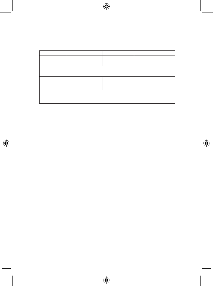
Function Range Resolution Accuracy
Temperature
(type K)
–50 to
1382°F 0.1°F ±(3.0% reading
+ 9°F/5°C digits) (probe
accuracy not included)
–45 to
750°C 0.1°C
Resistance
400 Ω0.1 Ω
±(1.2% reading
+ 4 digits)
4 kΩ0.001 kΩ
40 kΩ0.01 kΩ
400 kΩ0.1 kΩ
4 MΩ0.001 MΩ
40 MΩ0.01 MΩ±(2.0% reading + 20
digits)
Capacitance
40 nF 0.01 nF ±(5.0% reading + 10
digits)
400 nF 0.1 nF ±(3.0% reading + 5
digits)
4 µF 0.001 µF
40 µF 0.01 µF
400 µF 0.1 µF
4000 µF 1 µF ±(5.0% reading + 10
digits)
Frequency
(electronic)
9.999 Hz 0.001 Hz
±(1.5% reading + 5
digits)
99.99 Hz 0.01 Hz
999.9 Hz 0.1 Hz
9.999 kHz 0.001 kHz
99.99 kHz 0.01 kHz
999.9 kHz 0.1 kHz
9.999 MHz 0.001 MHz
Sensitivity: 0.8 V rms min @ 20 to 80% duty cycle
and<100 kHz; 5 Vrms min @ 20 to 80% duty cycle
and >100 kHz.
Note: Accuracy is stated at 65 to 83°F (18 to 28°C) and <75% RH.
Specifications (cont.)
1065DGMAN_20250-64_Rev1.indd 18 07/02/2019 11:23:03 AM
19
Function Range Resolution Accuracy
Frequency
(electrical)
10.00 to 400 Hz 0.01 Hz ±(0.5% reading)
Sensitivity: 15V rms
Duty Cycle
0.1 to 99.9% 0.1% ±(1.2% reading + 2
digits)
Pulse width: 100 µs to 100 ms,
Frequency: 5 Hz to 150 kHz
Note: Accuracy specifications consist of two elements:
(% reading) – This is the accuracy of the measurement circuit.
(+ digits) – This is the accuracy of the analog to digital converter.
1065DGMAN_20250-64_Rev1.indd 19 07/02/2019 11:23:03 AM
20
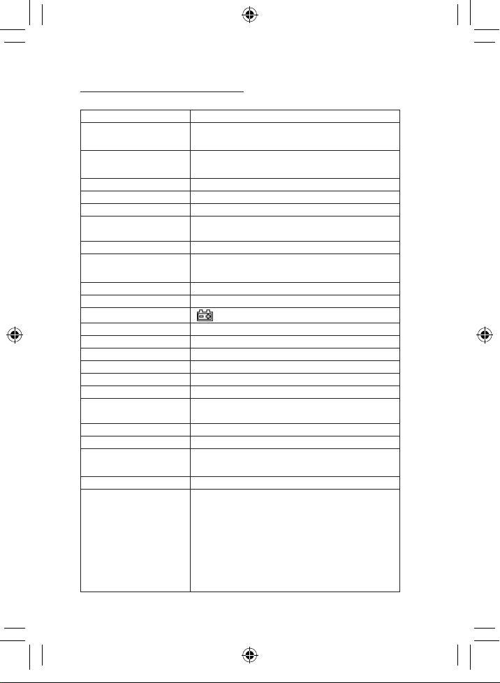
General Specifications
Bluetooth version 4.0
Diode test Test current of 0.9 mA maximum, open circuit
voltage 2.8 V DC typical
Continuity check Audible signal will sound if resistance is
<35 Ω(approx.); test current <0.35 Ma
Input impedance >10 MΩVDC and >10 MΩVAC
AC response True RMS
ACV bandwidth 50 to 400 Hz
Crest factor ≤3 at full scale up to 500 V, decreasing
linearly to ≤1.5 at 1000 V
Display 4000 counts LCD, backlighting and bar graph
Polarity Automatic. No indication for positive;
minus (–) sign for negative.
Measurement rate 2 times per second, nominal
Overrange indication ‘OL’ display
Low battery indication ‘’ is displayed
Auto power-off 15 minutes with disable feature
Battery One (1) 9 V (NEDA 1604) battery
Enclosure Double molded, waterproof
Shock (drop) test 6.5 ft (2 m)
Operating temp. 41 to 104°F (5 to 40°C)
Storage temperature –4 to 140°F (–20 to 60°C)
Operating humidity Max 80% up to 87°F (31°C) decreasing
linearly to 50% at 104°F (40°C)
Storage humidity <80%
Operating altitude 7000 ft (2000 m) maximum
Dimensions 75⁄32" x 37⁄32" x 25⁄16" (18.2 x 8.2 x 5.9 cm)
including holster
Weight 12.1 oz (342 g) including holster
Safety
This meter is intended for origin of
installation use and protected, against the
users, by double insulation per EN61010-1
and IEC61010-1 2 Edition (2001) to Category IV
600V and Category III 1000V; Pollution Degree
2. The meter also meets UL 61010-1, 2nd Edition
(2004), CAN/CSA C22.2 No. 61010-1 2nd Edition
(2004), and UL 61010B-2-031, 1st Edition (2003)
1065DGMAN_20250-64_Rev1.indd 20 07/02/2019 11:23:03 AM
Table of contents
Other Digi-Sense Multimeter manuals


