Digi-Shot UTM-00343 User manual
COMMANDER SYSTEM
QUICK REFERENCE
GUIDE
UTM-00343 |Rev 1 |2017
APPROVED

UTM-00343 |Rev 1
Page | 2
INDEX
1SYSTEMLIMITS..................................4
2PRE-USE CHECKLIST........................5
3CE4 TAGGER......................................6
3.1. SETTING UP TAGGER ..............................7
3.2. TAGGING ...............................................8
4COMMANDER...................................10
4.1. SET UP BENCH COMMANDER ................11
4.2. SET UP BASE COMMANDER...................15
4.3. SYSTEMDEPLOYMENT ..................18
4.4. TAG DETONATORS................................20
4.5. TEST DETONATORS ..............................27
4.6. VIEW DESIGN.......................................32
4.7. PREPARE FOR BLAST............................33
5TROUBLESHOOTING.......................38
5.1. CE4 TAGGER....................................38
5.2. COMMANDER .......................................43
6EMERGENCY CONTACT DETAILS.............48

UTM-00343 |Rev 1
Page | 3
1. Think through the task
2. Identify the hazards
3. Eliminate or manage the hazards
4. Assess the remaining risk
5. Do the job safely

UTM-00343 |Rev 1
Page | 4
The 4G system limits must be adhered to at all times to
ensure that blasts are successfully initiated.
Maximum harness wire per channel 2,500m
Maximum downline per channel 12000m
Maximum Bench Commanders per Base
Commander 10
Maximum detonators per Tagger 16000
Maximum detonators per Channel 400
Maximum detonators per Bench Commander 1600
Maximum detonators RF 16000
Maximum detonators standalone 1600
Maximum detonators per hole 6 decks x
3 dets
each =
18 dets
Maximum holes per string 400
Maximum strings per blast design 44
Maximum line-of-sight for Remote Firing 3km
Maximum delay for any detonator 20,000ms
Minimum delay per detonator 0ms
Minimum delay increment 1ms
Maximum Wi-Fi connectivity distance 10m

UTM-00343 |Rev 1
Page | 5
Prior to arrival on the bench:
1. Ensure Commanders and Taggers are
fully charged.
2. Check for latest software version
3. Check communications settings on Bench
Commander and Base Commander
correspond.
4. Ensure Smart Cards are available and
check serial numbers to ensure they are
paired.
5. Ensure dates and times on control
equipment are correctly set.
6. Ensure correct amount of detonators and
harness wire are delivered to the bench.
7. Ensure that blast layout is correctly loaded
onto Tagger.
8. Ensure a copy of Tagging Plan is
available.
9. Ensure pre-planning is performed.
UTM-00343 |Rev 1
Page | 6
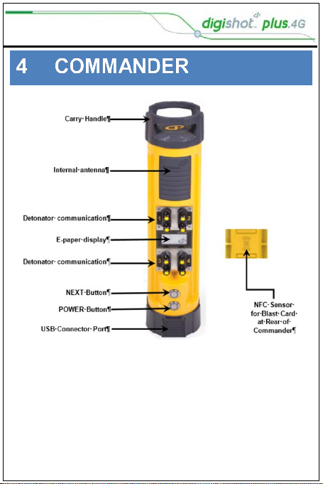
Harness wire terminals
Pogo Pin Connector
Blue Status
White Charge
Red Error LED
LCD Screen
Soft Keys
Enter Key
Backspace Key
Escape Key
On/Off
Numerical Keys
USB Connector
UTM-00343 |Rev 1
Page | 7
Turn Tagger ON
Enter Password (Default password 9949 - If required)
Configure Tagger
From Main Menu press configuration soft key.
Once in the CONFIGURATION menu press:
1to enter 4G Setup
2to enter Device Setup
3to enter Advanced Setup
4to enter Factory Setup (Password protected)
The Device SETUP menu will allow you to:
Adjust the Screen CONTRAST
Adjust the Screen Brightness
Set the TIME ZONE for your location. (GMT+2 for SA)
To set the Auto Shutdown time for the Tagger
Choose one of 3 Languages – ENGLISH, SPANISH
and FRENCH
Set up the conversion units used i.e. Imperial or
Metric
The Advanced SETUP menu will allow you to:
Assign Tagger ID (using multiple taggers)
Link up PC to Tagger through Wi-Fi
Link up PC to Tagger through a USB cable
Link up Commander to Tagger through Wi-Fi
Remote view on your PC (USB)
Clear Det IDs (incorrectly tagged dets)
Change the Device Password
Press “Home” soft key to return to “Main Menu”
UTM-00343 |Rev 1
Page | 8
SET UP TAGGER FOR TAGGING
Tag Option
Basic: Delay Option (D)
Planned: Tag by Plan Option (P)
Advanced: Location and Delay Option (A)
Once the option is set, the corresponding symbol will be
displayed in the top bar.
Main Menu
Press SoftKey to select Configuration Settings.
Press to select 4G Setup
Press to select Tag Option
Use navigational keys to scroll up/down and
display the required selection as follows:
Press SoftKey to save option as required.
Press SoftKey to return to Main Menu

UTM-00343 |Rev 1
Page | 9
Site Setup
Main Menu
Press SoftKey to select Configuration Settings.
Press to select 4G Setup
Press to select Site Setup
Site Setup screen for each tagging mode
Use Markers: When this item is enabled (Black filled
rectangle), the tagging screen will contain a soft key to
allow marking and tagging a detonator at the same
time.
Autotag: If this option is disabled (White filled
rectangle), tagging can only be performed on the pogo
pins, and not by connecting a detonator onto the
harness wire (It is not practical to connect and then
remove the detonator from the harness wires).
Multi Commander: allows the user to load blast designs
for multiple commanders up to 16 000 dets
Multi-Primed: Enables setting of multiple dets per shot
hole.
Assign Locations: Allows for tagging locations without
timing to detonators
List Hole Config: Setting of decks and dets per deck.
Det Label: Configures how locations is tagged to
detonators i.e. numerical or Alfa-numerical.
Delete ViewShot: Clears ViewShot Plan in Planned
mode.
UTM-00343 |Rev 1
Page | 10
UTM-00343 |Rev 1
Page | 11
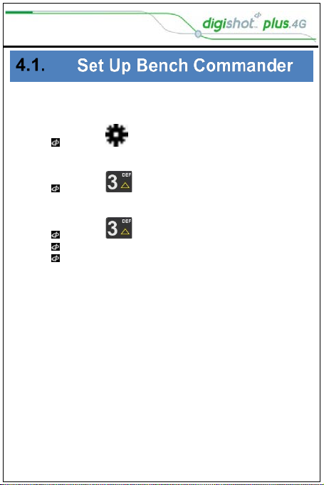
Power up the Commander
1. Main Menu
Press to select Configuration
2. Configuration Menu
Press to select Advanced Setup
3. Advanced Setup
Press to select Bench Box Mode
Bench Box Mode will be activated
User will be prompted to shut the CE4 Commander
down and restart for the change to take effect
UTM-00343 |Rev 1
Page | 12
Connecting CE4 Tagger to CE4 Commander via Wi-Fi
ENSURE THAT THE BENCH IS CLEARED BEFORE THE DETONATORS OR
CE4 TAGGER IS CONNECTED TO THE BENCH COMMANDER.
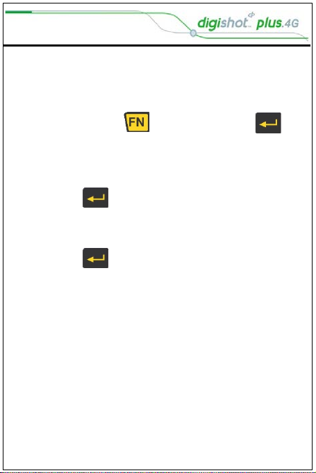
1. Switch both the Commander and the Tagger ON
2. Press and hold key and then press the key
to connect CE4 Tagger to CE4 Commander via Wi-Fi
Observe the Commander ID
3. Enter the Commander ID
4. Press key to connect to Commander
5. CE4 Tagger will connect to Commander
6. Enter device password when prompted
7. Press key to continue
Device password will be required only during first
connection to the Commander.
8. CE4 Commander Main Menu will be displayed
UTM-00343 |Rev 1
Page | 13
Set up RF Channel (Only used when not hard set by DNAP
technical department)
NOTE (Using paired Blast Cards will set the RF channel and
Key automatically)
NOTE (The Bench Commander and Base Commander must
have the same Software version, RF Key and the same RF
channel for successful communication to take place)
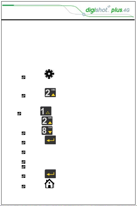
Main Menu
Press to select Configuration
1. Configuration Menu
Press to select Long Range RF
2. Remote Blast
Press to select Set RF Channel
Use navigational keys to navigate selection.
Press to select Region and open RF Channel
selection.
Use numerical keypad to enter Unique RF Channel
range as follows:
Between 16 and 49 for Americas
Between 48 and 55 for Australia.
Press to continue
Press SoftKey to return to Main Menu
UTM-00343 |Rev 1
Page | 14
Set Encryption Key
1. Main Menu
Press to select Configuration
2. Configuration Menu
Press to select Long Range RF
3. Remote Blast
4. Press to select Set Encryption Key
Set Encryption Key (Only used when not hard set by DNAP
technical department)
Key will be displayed
Press to change
Use numerical keypad to enter New Key
Press to continue
Press SoftKey to return to Main Menu

UTM-00343 |Rev 1
Page | 15
1. Main Menu
Press to select Configuration
2. Configuration Menu
Press to select Advanced Setup
3. Advanced Setup
Press to select Base Station Mode
4. Base Station Mode
Press to select Base Station Mode
Base Station Mode will be activated
User will be prompted to shut the CE4 Commander
down and restart for the change to take effect
Set up RF Channel
NOTE (Using paired Blast Cards will set the RF channel and
Key automatically)
NOTE: The Bench Commander and Base Commander MUST
have the same Software version, RF Key and the same RF
channel for successful communication to take place) Refer
to Page 14 above for setup detail.

UTM-00343 |Rev 1
Page | 16
Base + Repeat Mode
1. Main Menu
Press to select Configuration
2. Configuration Menu
Press to select Advanced Setup
3. Advanced Setup
Press to select Base Station Mode
4. Base Station Mode
Press to select Base + Repeat Mode
Base + Repeat Mode will be activated
User will be prompted to shut the CE4 Commander
down and restart for the change to take effect
UTM-00343 |Rev 1
Page | 17
Repeater Mode
1. Main Menu
Press to select Configuration
2. Configuration Menu
Press to select Advanced Setup
3. Advanced Setup
Press to select Repeater Mode
Repeater Mode will be activated
User will be prompted to shut the 4G CE4
Commander down and restart for the change to take
effect.
UTM-00343 |Rev 1
Page | 18
NO DETONATOR SHALL BE CONNECTED
TO THE TAGGER WHILST THE CE4
TAGGER IS CONNECTED TO A CHARGER
Inherent Safety
CE4 Taggers are said to be
INHERENTLY SAFE because they
cannot produce the necessary
minimum required firing voltage to
blast the electronic 4G detonator.
The CE4 Tagger is also unable to
produce the encoded FIRING
SIGNAL necessary to initiate a blast.
The CE4 Tagger must NEVER be
connected to a normal electric
detonator or a suspected
damaged/shrink wrapped detonator.

UTM-00343 |Rev 1
Page | 19
Safety Warnings
Batteries may leak or explode if incorrectly
handled.
Only use batteries approved for use in the
CE4 Tagger.
Do not expose the battery to an open flame or
excessive heat.
Replacing external batteries in the battery
pack must be done in a safe and dry place so
as to prevent ingress of moisture or
condensation into the battery pack enclosure.
Do not apply undue pressure to the LCD
screen as this could damage the Tagger or
cause a malfunction.
Should the LCD screen break, care should be
taken to avoid injury from broken glass and to
prevent liquid crystal from the screen touching
the skin or entering the eyes and mouth.

UTM-00343 |Rev 1
Page | 20
1. From the Main Menu
Press to select New Design
Type in delay required
2. Tag Detonators Warning
Press OK SoftKey to acknowledge warning
This detonator warning message will only be displayed when the
user opens the tagging screen on the initial start-up of the device.
3. Enter desired delay
Use the keypad to enter the delay in milliseconds
Connect detonator and press to continue
Detonator number and delay entered will be displayed
Tagger will be in ready state to enter next detonator
delay
4. Press to select Tag Detonators to continue tagging
after leaving the tag screen
Table of contents
Other Digi-Shot Test Equipment manuals


