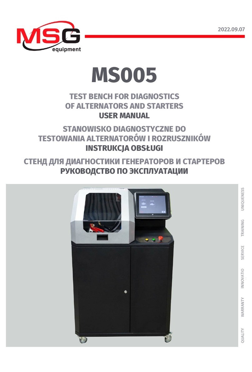
MSG Equipment MS008 User manual

2022.09.07
MS008
TEST BENCH FOR DIAGNOSTICS OF ALTERNATORS,
STARTERS AND VOLTAGE REGULATORS
USER MANUAL
STANOWISKO DO DIAGNOSTYKI ALTERNATORÓW,
ROZRUSZNIKÓW ORAZ REGULATORÓW NAPIĘCIA
INSTRUKCJA OBSŁUGI
СТЕНД ДЛЯ ДИАГНОСТИКИ ГЕНЕРАТОРОВ, СТАРТЕРОВ
И РЕГУЛЯТОРОВ НАПРЯЖЕНИЯ
РУКОВОДСТВО ПО ЭКСПЛУАТАЦИИ
UNIQUENESS
TRAINING
SERVICE
INNOVATION
WARRANTY
QUALITY


English
User manual
3
CONTENTS
INTRODUCTION....................................................................................................................................................4
1. APPLICATION....................................................................................................................................................4
2. SPECIFICATIONS..............................................................................................................................................5
3. EQUIPMENT SET .............................................................................................................................................. 7
4. TEST BENCH DESCRIPTION........................................................................................................................... 7
5. APPROPRIATE USE........................................................................................................................................12
5.1. Safety Guidelines ...............................................................................................................................12
5.2. Installation and connection of test bench..................................................................................13
6. TEST BENCH MAINTENANCE........................................................................................................................14
6.1. Test bench software update............................................................................................................14
6.2. Cleaning and care..............................................................................................................................14
7. TROUBLESHOOTING GUIDE.........................................................................................................................15
8. RECYCLING.....................................................................................................................................................15
CONTACTS...........................................................................................................................................................16

English
Test bench MS008
4
INTRODUCTION
We appreciate you have chosen the products of TM MSG equipment.
The present user manual consists of the information on the application, supply slip, design,
specifications and rules of usage of test bench MS008.
Prior to using the test bench MS008 (hereinafter, “the bench”), study the present user manual
thoroughly. If required, get the special training at bench manufacturer facilities.
Due to the permanent improvements of the bench, the design, supply slip and software are
subject to modifications that are not included to the present user manual. Pre-installed bench
software is subject to update. In future, its support may be terminated without a prior notice.
1. APPLICATION
The bench is designed to perform the following tasks:
1. Evaluation of the technical condition of automotive alternators with alternating current rated
voltage 12 and 24V under the load up to 150 and 75A accordingly, including alternators of system
«start-stop» 12V.
2. Test of performance capacity of 12/24V voltage regulators - separately from alternators.
3. Diagnostics of automotive starters with power of 11kW, without load (at idle).
The diagnostics of automotive alternators and voltage regulators takes into account the following
criteria:
- Stabilizing voltage;
- control lamp working performance capacity;
- FR (displaying of the frequency and FR duty ratio, voltage regulator response).
- The AC pulsation value.
For COM alternator types (voltage regulators):
- ID;
- Protocol;
- data exchange speed;
- LIN protocol type;
- regulator self-diagnostics errors.
The diagnostics of the automotive starters considers the voltage changes nature and the currents
on the terminals 30, 45 and 50.

English
User manual
5
2. SPECIFICATIONS
Main
Supply voltage, V
400
Supply mains type
Three phase
Drive power, kW
4
Dimensions (L x W x H), mm
770×640×500
Weight, kg
100
Quantity of storage batteries
(not included into supply slip) 2 similar lead-acid 12V storage batteries
Storage battery
Capacity from 45 up to 60 A-h and
dimensions (L x W x H) not exceeding
207×175×175 mm
Storage battery automatic charging No.1
Available
Storage battery automatic charging No.2
Available
Rated voltage of the diagnosed units, V
12, 24
Alternator diagnostics
Load, A
12V
150А
24V
75А
Verification regime
Automatic/manual
Load adjustment (0-100%)
Smoothly
Drive speed, rpm
0-3000
Drive speed adjustment
Smoothly
Drive type (alternator drive)
V-belt drive/Poly V-belt drive
Types of diagnosed alternators 12V
Lamp, SIG, RLO, RVC, C KOREA, P-D,
C JAPAN, COM (LIN, BSS), S/A PSA
24V
Lamp, COM (LIN)

English
Test bench MS008
6
Starter diagnostics
Power of diagnosed starters, kW
up to 11
Measured parameters
The charts displaying the operation starting
mode, voltage variations and current on the
terminals: К30, К50 и К45
Voltage regulator diagnostics
Engine rotation imitation, rpm
from 0 up to 6000
Voltage regulator load imitation, %
from 0 up to 100
Types of diagnosed voltage
regulators
12V
Lamp, SIG, RLO, RVC, C KOREA, P-D,
C JAPAN, COM (LIN, BSS)
24V
Lamp, COM (LIN)
Optionally
Display
Touch Screen 7”
Software update
Available
Alternator database
Available
Voltage regulator database
Available
Diagnostics results storage
Available
Printing
Available
Internet connection
Wi-Fi (802.11 a/b/g/ac)
Connection of peripheral devices
2 x USB 2.0
1 х HDMI

English
User manual
7
3. EQUIPMENT SET
The equipment set includes:
Item name
Number of
pcs
Test bench MS008
1
MS33001 – a cable with a kit of adapting wires
1
Cable for starter diagnostics
1
Alternator positive terminal adapter
2
MS0114 - Cutout fuse (type 22x58 mm, current 100А)
1
Module Wi-Fi
1
Socket 400V
1
User Manual (card with QR code)
1
4. TEST BENCH DESCRIPTION
The bench consists of the following main elements (fig. 1):
Figure 1. Overall view of test bench
1– Unit fixing chain.
2– Alternator drive belts: V-belts and poly V-belts.

English
Test bench MS008
8
3– Protective housing. When the protective housing is up, the diagnostics will be blocked.
4– Power cables В+, В-.
5– Front panel.
6– Battery location section.
There are the following diagnostic cable connection ports on the front panel:
Figure 2. Bench front panel
1– Connection ports used for diagnostics of voltage regulators:
• В+ – voltage regulator positive (terminal 30 and terminal 15);
• В-– voltage regulator negative (earth, terminal 31);
• ST1, ST2 – ports for voltage regulator stator inputs (terminals) connection: P, S, STA, Stator;
• F1, F2 – ports for the connection of voltage regulator brushes or relevant terminals: DF, F,
FLD.
2– Port for the connection of diagnostic cable to the starter terminal 50.
3– Diagnostic cable connection port.
4– Touch screen - to display diagnostic parameters of a diagnosed unit and to control the bench
functions.
5– Buttons to control the tightening and loosening of alternator drive belt and unit fixing chain.
Button „OFF/ON”– is responsible for the power on the bench. The bench is turned off by pressing
the button “Turn off the bench” in the main menu of the service program.
Button „EMERGENCY STOP”– emergency stop of generator drive and chain/belt tightening.

English
User manual
9
On the right side of the bench are two USB ports for connecting the computer periphery (mouse,
keyboard, WiFi adapter) and one HDMI port for connecting the monitor.
Figure 3. Connectors on the side panel of the bench:
1 – HDMI; 2 – USB
The bench supply slip includes the diagnostic cable (fig. 4) that consists of the adapting wire kit
(fig. 5) - for more convenient connection to alternator connection terminals or relay regulator.
Figure 4. Diagnostic cable MS-33001
The diagnostic cable MS-33001 has the following adapting wire colour codes (see also Table 1):
•Orange - S(Sense Pin) - the terminal that enables the measuring of the storage battery voltage
by the voltage regulator as well as it compares the storage battery voltage with the alternator
output voltage. This adapting cable is connected to terminal S;
•Red – IG (Ignition) – the terminal is used for the connection of the ignition circuit, the
terminals: 15, A, IG;

English
Test bench MS008
10
•White – FR – the terminal that transmits the data on the regulator load. This adapting wire is
connected to the following terminals: FR, DFM, M;
•Gray – D+ – the terminal for the connection of the circuit of voltage regulator control lamp. It’s
connected to the terminals: D+, L, IL, 61;
•Yellow – GC – is used for the connection of the channel of alternator voltage regulator control.
This adapting wire is connected to the following terminals: COM, SIG, etc.
•Brown – К30 – is connected to the starter terminal 30 that is connected to the storage battery
terminal +.
•Violet – К45 – is connected to the starter solenoid output connected to starter electric motor.
Figure 5. Adapting wire kit

English
User manual
11
Table 1 – Colour codes of cable MS-33001
Connector
Terminal
S
IG
FR
D+
GC
K30 (starter)
K45 (starter)
Use the cable MS-33001 and wire kit (fig. 6) to test the voltage regulators separately from
alternator.
Figure 6. Wire kit for diagnostics of voltage regulators
For the diagnostics of the starter, use the cable MS-33001 and the cable for the connection of
the terminal 50 (fig. 7).

English
Test bench MS008
12
Figure 7. Cable for the connection of starter terminal 50
5. APPROPRIATE USE
1. Use the bench for the specified purpose only.
2. Turning off the bench should be done through the interface of the service program by pressing
the "Turn off the bench" button.
3. Press EMERGENCY STOP button only for the crisis shut down of bench drive, tightening, and to
cut off the power clip supply.
4. In case of failures in the operation of the bench, stop further operation and contact the
manufacturer or sales representative.
The manufacturer is not responsible for any damage or injury to human health resulting from
non-compliance with the requirements of this user manual.
5.1. Safety Guidelines
1. The bench has to be operated by the qualified persons who got the access to operate the
definite bench types and who were instructed on the safe operating procedures and methods.
2. The bench has to be turned off if the supply is terminated, during the cleaning and tidying up,
as well as in the emergency situations.
3. The work area must always be clean, with good light illumination, and spacious.
4. To ensure electrical and fire safety PROHIBITED:
- connect the bench to the electrical network having faulty protection against current overloads
or not having such protection;
— use a socket without a grounding contact to connect the bench;
— use extension cords to connect the bench to the electrical network. If the socket is far from the
bench installation site, it is necessary to modify the electrical network and install the socket;
- operation of the bench in defective condition.
- Independently to repair and make changes to the design of the bench, because it can lead to
serious damage to the bench and deprive the right to warranty repair.
5. It’s forbidden to leave the units with running drive on the bench unattended.

English
User manual
13
6. While mounting and dismounting of a unit from the bench, to prevent arms from harming, be
more cautious.
5.2. Installation and connection of test bench
The bench is delivered packed. Release the bench from the packaging materials, remove the
protective film from the display (if available). After unpacking, it is necessary to make sure that
the bench is intact and does not have any damage. If damage is detected before the bench is
activated, contact the manufacturer or the sales representative.
The bench has a desktop version. When installing the bench, it is necessary that it is supported
by legs that can be adjusted in height by twisting or screwing them. The bench must be stable.
After the bench is transported at an ambient temperature of less than 0°C, it shall be kept at a
working temperature of at least 24 h before being turned on.
The bench ensures the operation at the temperature from +100C up to +400C and relative air
humidity from 10% up to 75%.
When installing the bench, keep the minimum space gap 0.5 m from the rear bench side - for a
proper air circulation.
Prior to the bench operation, connect:
•Storage batteries 12V that have to be located in the storage battery section of the bench (fig.8).
While connecting the storage batteries refer to the power cable markings. If only one battery
is connected (either battery 1 or battery 2) just 12V diagnostics mode will be available. 24V
mode is not active.
•Electric circuit of 400V – referring to the markings inside of socket (included into supply slip).
Figure 8. Location of the storage batteries in the bench

English
Test bench MS008
14
6. TEST BENCH MAINTENANCE
The bench is designed for a long operation life and doesn’t have any special maintenance
requirements. At the same time, to ensure the maximum operation life, the regular monitoring of
bench technical condition should be made as follows:
• Motor operation inspection (uncommon noises, vibration etc.);
• Alternator drive belts condition (visual inspection);
• Condition of power wires for the connection of unit to bench ports (visual inspection);
• inspection of bench operation environment (temperature, humidity, vibration etc.).
6.1. Test bench software update
Being connected to the Internet, with every switching on, the test bench checks for software
updates of diagnostics program, database and bench firmware. In case the bench finds the
software update at company server, you’ll be offered to install the update or disregard it. To start
updating, press OK, to decline – SKIP.
NOTE! Updates may take a while to install.
WARNING! It’s forbidden to switch off the bench supply to stop the updating.
6.2. Cleaning and care
To clean the bench surfaces, use either the soft napkins or rags, and neutral cleansers. The display
should be cleaned with a special fiber display cleaning cloth and with a spray for display cleaning.
To prevent the bench from the failure and corrosion, do not use abrasive materials and solvents.

English
User manual
15
7. TROUBLESHOOTING GUIDE
Below you will find the table with the possible problems and the solutions on their elimination.
Problem Causes Solutions
1. The bench doesn’t
start.
Automatic cut-out activated.
Unscrew the rear bench cover,
set the automatic cut-out into
up position.
One of the bench supply
phases (L1/L2/L3) is not active,
or neutral N
Restore the supply
2. The bench runs but
the electric motor
doesn’t start.
The variable speed drive
software error.
Contact the dealer
The bench wiring is damaged.
3. When the bench runs
the abnormal noises are
heard.
The diagnosed unit is mounted
wrong. (The drive belt over
tightened or out of alignment)
Re-mount the unit for the
diagnostics
4. When the bench runs
the belt slips (whistles).
The belt tightening is not
enough
Stop the drive and check the
tightening intensity
The wear of the belt
Replace the belt
5. During the alternator
test the contact clips
heat up much. (alligator
clips)
The contact area is small Use a positive terminal adapter
of the alternator
8. RECYCLING
For the recycling of the bench refer to the European Directive 2202/96/EC (WEEE Directive - the
directive on waste electrical and electronic equipment).
The outdated electronic devices and electrical appliances, including the cables, hardware,
batteries and storage batteries shall be disposed separately from the house waste.
To dispose the waste products, exploit the available returning and collecting systems.
The appropriate disposal of the outdated devices helps to prevent harming to environment and
health.

English
Contacts
16
MSG equipment
HEADQUARTERS AND PRODUCTION
18 Biolohichna st.,
61030 Kharkiv
Ukraine
+38 057 728 49 64
+38 063 745 19 68
E-mail: [email protected]
Website: servicems.eu
REPRESENTATIVE OFFICE IN POLAND
STS Sp. z o.o.
ul. Modlińska, 209,
Warszawa 03-120
+48 833 13 19 70
+48 886 89 30 56
E-mail: [email protected]
Website: msgequipment.pl
TECHNICAL SUPPORT
+38 067 434 42 94
E-mail: support@servicems.eu

Polish
Instrukcja obsługi
17
SPIS TREŚCI
WSTĘP .................................................................................................................................................................18
1. PRZEZNACZENIE ............................................................................................................................................18
2. DANE TECHNICZNE........................................................................................................................................19
3. ZESTAW...........................................................................................................................................................21
4. OPIS STANOWISKA.......................................................................................................................................21
5. ZASTOSOWANIE ZGODNE Z PRZEZNACZENIEM ..................................................................................... 26
5.1. Wskazówki dotyczące BHP.............................................................................................................. 26
5.2 Montaż i podłączenie stanowiska...................................................................................................27
6. OBSŁUGA STANOWISKA............................................................................................................................. 28
6.1. Aktualizacja oprogramowania stanowiska ................................................................................. 28
6.2. Czyszczenie i codzienna obsługa.................................................................................................. 28
7. GŁÓWNE USTERKI I METODY ICH USUNIĘCIA......................................................................................... 29
8. UTYLIZACJA ................................................................................................................................................... 29
KONTAKTY......................................................................................................................................................... 30

Polish
Stanowisko MS008
18
WSTĘP
Dziękujemy za wybór produktów marki handlowej MSG equipment.
Niniejsza Instrukcja obsługi zawiera informacje na temat przeznaczenia, zestawu, konstrukcji,
danych technicznych i zasad eksploatacji stanowiska MS008.
Przed użyciem MS008 (dalej w tekście stanowisko) należy uważnie przeczytać niniejszą Instrukcję
obsługi i w razie potrzeby odbyć specjalne szkolenie w zakładzie produkcyjnym stanowiska.
W związku z ciągłym ulepszaniem stanowiska w zakresie konstrukcji, zestawu i oprogramowania
mogą zostać wprowadzone zmiany, które nie zostały uwzględnione w niniejszej Instrukcji obsługi.
Oprogramowanie zainstalowane na stanowisku podlega aktualizacji, a jego wsparcie może zostać
zakończone bez wcześniejszego powiadomienia.
1. PRZEZNACZENIE
Stanowisko jest przeznaczone do wykonania poniższych zadań:
1. Ocena stanu technicznego samochodowych alternatorów prądu przemiennego o napięciu
znamionowym 12 i 24 V pod obciążeniem odpowiednio do 150 i 75 A, w tym alternatorów układu
„START-STOP” 12V.
2. Badanie sprawności regulatorów napięcia12/24V oddzielnie od alternatora.
3. Diagnostyka rozruszników samochodowych o mocy do 11 kW bez obciążenia na biegu jałowym.
Diagnostyka alternatorów samochodowych i regulatorów napięcia odbywa się zgodnie z
poniższymi kryteriami:
- Napięcie stabilizacji;
- Sprawność lampki kontrolnej;
- FR (Wyświetlanie częstotliwości i wypełnienia impulsu sygnału FR, sprzężenie zwrotne
regulatora napięcia).
- Wartość tętnień prądu przemiennego.
Dla alternatorów COM (regulatory napięcia):
- ID;
- Protokół;
- Szybkość wymiany danych;
- Typ protokołu LIN;
- Błędy autodiagnozy regulatora.
Diagnostyka rozruszników samochodowych odbywa się wg charakteru zmiany napięć i prądów na
klemach 30, 45 i 50.

Polish
Instrukcja obsługi
19
2. DANE TECHNICZNE
Główne
Napięcie zasilania, V
400
Typ sieci zasilającej
Trójfazowa
Moc napędu, kW
4
Wymiary (DxSxW), mm
770×640×500
Masa, kg
100
Liczba podłączanych akumulatorów
2 identyczne kwasowo-ołowiowe po 12V
Model akumulatora (nie jest zawarty w
zestawie)
Pojemności od 45 do 60 Ah i wymiary
(dł.×szer.×wys.) nie więcej niż:
207×175×175 мм
Automatyczne ładowanie akumulatora nr 1
Tak
Automatyczne ładowanie akumulatora nr 2
Tak
Napięcie znamionowe badanych jednostek, V
12, 24
Badanie alternatorów
Obciążenie, A
12V
150A
24V
75А
Tryb badania
Automatyczny/ręczny
Regulacja obciążenia (0-100%)
Płynnie
Obroty napędu, obr/min
0-3000
Regulacja obrotów napędu
Płynnie
Typ przekładni (napęd-alternator)
Pas klinowy / wieloklinowy
Rodzaje testowanych alternatorów 12V
Lamp, SIG, RLO, RVC, C KOREA, P-D,
C JAPAN, COM (LIN, BSS), S/A PSA
24V
Lamp, COM (LIN)
Badanie rozruszników
Moc badanych rozruszników, kW
do 11

Polish
Stanowisko MS008
20
Parametry mierzone
Wyświetlanie na ekranie w postaci
wykresów trybu uruchamiania, zmiany
napięcia i prądu na klemach: К30, К50 и К45
Kontrola regulatorów napięcia
Symulowane obroty silnika, obr/min
od 0 do 6000
Symulowane obciążenie regulatora napięcia,
% od 0 do 100
Rodzaje badanych regulatorów
napięcia
12V
Lamp, SIG, RLO, RVC, C KOREA, P-D,
C JAPAN, COM (LIN, BSS)
24V
Lamp, COM (LIN)
Dodatkowo
Wyświetlacz
Dotykowy 7"
Aktualizacja oprogramowania
Tak
Baza danych alternatorów
Tak
Baza danych regulatorów napięcia
Tak
Zapisywanie wyników diagnostycznych
Tak
Wydruk
Tak
Połączenie z Internetem
Wi-Fi (802.11 a/b/g/ac)
Podłączanie urządzeń peryferyjnych
2 x USB 2.0
1 х HDMI
Table of contents
Languages:
Other MSG Equipment Test Equipment manuals
MSG Equipment
MSG Equipment MS021 User manual

MSG Equipment
MSG Equipment MS1000+ User manual
MSG Equipment
MSG Equipment MS002 COM User manual

MSG Equipment
MSG Equipment MS121 User manual
MSG Equipment
MSG Equipment MS016 User manual

MSG Equipment
MSG Equipment MS603N User manual

MSG Equipment
MSG Equipment MS121 User manual
MSG Equipment
MSG Equipment MS016 User manual
MSG Equipment
MSG Equipment MS800 User manual

MSG Equipment
MSG Equipment MS1000+ User manual