digico S Series User manual

TN 559 –Cleaning and replacing faders - All consoles Page 1
TECHNICAL NOTE
Date: 22nd November 2022
Ref: 559
Raised by: TS
Distributed to: as required
DiGiCo (UK) Ltd. Unit 10 Silverglade Business Park, Chessington, Surrey, KT9 2QL, UK
Tel: +44 1372 845600 email: support@digiconsoles.com
Replacing and Cleaning Faders on SD, Quantum, and S-Series Consoles
Symptoms:
Dirty or worn faders may jitter or jump, and randomly and inaccurately respond when moving to a position.
This is easiest to see when a bank is recalled and the faders should be positioning themselves at 0dB, but
instead they miss their target position and stop, or they quickly bounce until they reach their target position.
These symptoms are usually found on old and worn faders, and while cleaning may help, they will ultimately
need to be replaced.
Faders that are stiff or running rough are usually dirty and will require either careful cleaning or
replacement. It is often quicker to replace faders rather than individually clean them.
You will need:
•2mm Hex driver for the fader panel retaining screws
•5mm Hex driver for SD9/10/11 end cheeks
•1.5mm Hex driver for the fader retaining screws
•PZ1 screwdriver for M3 screws
•Compressed air
•Vacuum cleaner
•Clean paint brush
•Specialist electronics cleaner-lubricant such as Deoxit F5 or Servisol S10 with a thin nozzle applicator
•Paper towels
•Antistatic wrist or ankle strap, connected to an electrical ground/earth
Which console? Click the console type to jump to the appropriate section
Quantum 2/3 or SD12
SD7Q/SD5Q/SD7/SD5
SD9/10/11
SD8
S-Series
IMPORTANT: Fader Calibration never fixes faulty fader operation, and can often
make the situation much worse, by calibrating to moving dirt!
Do not calibrate faders unless instructed to do so by DiGiCo Support

TN 559 –Cleaning and replacing faders - All consoles Page 2
Quantum 2 / Quantum 3 / SD12
This section is for the cleaning and replacement of faders in Quantum 2, Quantum 3, and SD12 consoles
only. If it feels like the faders are sticking, then either replacement or thorough cleaning is required.
Part Numbers –see Appendix 1 –Fader Table for full details
•Input fader: 681-00200 Input fader with plug –SD12, Q2, Q3 (and Q3 master section)
•Master fader: 681-00199 Master fader with plug –SD12, Q2
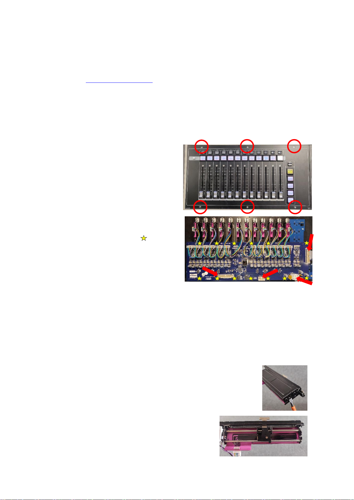
Replacing Faders
1. Power down the console, switch off the PSU’s
and connect your antistatic strap to an
appropriate earthing point.
2. Unscrew the fader panel (Q3 panel shown
opposite) with the 2mm Hex driver
3. Carefully tilt the panel and disconnect the
cables to the PCB’s (indicated below with
arrows), and the fader connectors.
4. Carefully unscrew the fader driver PCB
retaining screws (indicated above as yellow
stars ), store the fader driver card
somewhere safe.
5. Flip the panel back over and remove the
fader knobs and store them somewhere
safe.
6. Use a Hex driver to remove the screws at the
top and bottom of the first fader, store them
somewhere safe.
7. Carefully remove the fader and place to one side.
8. Repeat the fader removal (steps 6 and 7) and place them to one side keeping the sequence of
faders, do not mix them up –label them if necessary.
9. Using the vacuum cleaner and the paintbrush, gently clean the panel, PCBs, and the area inside of
the console.
10. Install the new faders, screw down the fader driver PCB, plug the faders into the PCB, and carefully
re-plug the connectors to the PCB’s. Place the fader panel back into the console, switch the console
on and test the functionality of the faders and buttons –the panel can now be screwed back into
place.
Cleaning Faders - Follow steps 1 –9 above
11. Use the compressed air to dislodge any dust and dirt from the inside of the fader assembly, then use
the vacuum cleaner to remove the dust and dirt. Repeat as necessary.
12. Lay the fader on paper towels, place the thin nozzle of the cleaner-lubricant spray along the fader
slot and with the fader at one end spray for no more than 1 second.
13. Move the fader up and down approximately 20 times and use the paper towel to wipe up any excess
or dirty liquid.
14. Repeat steps 11 - 13 for the remaining faders.
15. Re-install the faders, screw down the fader driver PCB, plug the faders into the PCB, and carefully re-
plug the connectors to the PCB’s. Place the fader panel back into the console, switch the console on
and test the functionality of the faders and buttons –the panel can now be screwed back into place.
TN 559 –Cleaning and replacing faders - All consoles Page 3
SD7Q / SD5Q / SD7 / SD5
This section is for the cleaning and replacement of faders in Quantum 7, Quantum 5, SD7 and SD5 consoles
only.
Part Numbers –see Appendix 1 –Fader Table for full details
•Input fader: SC-SD7-FADERI 100mm Input fader with plug –SD7Q, SD5Q, SD7, SD5
•Master fader: SC-SD7-FADERL 100mm Master fader with plug –SD7Q, SD7
•Upper fader: SC-SD7-FADERM 60mm Upper fader with plug –SD7Q, SD7
•Upper fader: SC-SD7-FADERML 60mm Upper Master fader with plug –SD7Q, SD7
Replacing Lower (100mm) Faders
1. Power down the console, switch off the PSU’s
and connect your antistatic strap to an
appropriate earthing point.
2. Unscrew the fader panel (SD5 panel shown
opposite) with the 2mm Hex driver
3. Carefully tilt the panel and disconnect the
cables to the PCB’s (SD5 card below with
arrows), and the fader connectors.
4. Carefully unscrew the fader driver PCB
retaining screws (SD5 card opposite with
screws indicated as yellow stars ), store the
fader driver card somewhere safe
5. Flip the panel back over and remove the fader
knobs and store them somewhere safe.
6. Use a Hex driver to remove the screws at the
top and bottom of the first fader, store them
somewhere safe.
7. Carefully remove the fader and place to one side.
8. Repeat the fader removal (steps 6 and 7) and place them to one side keeping the sequence of
faders, do not mix them up –label them if necessary.
9. Using the vacuum cleaner and the paintbrush, gently clean the panel, PCBs, and the area inside of
the console.
10. Install the new faders, screw down the fader driver PCB, plug the faders into the PCB, and carefully
re-plug the connectors to the PCB’s. Place the fader panel back into the console, switch the console
on and test the functionality of the faders and buttons –the panel can now be screwed back into
place.
Cleaning Lower (100mm) Faders - Follow steps 1 –9 above
11. Using a flat bladed screwdriver, gently prise the cover off the fader
12. Use the compressed air to dislodge any dust and dirt from the inside of the
fader assembly, then use the vacuum cleaner and paintbrush to remove the
dust and dirt. Repeat as necessary.
13. Lay the fader on paper towels, then with the fader at one
end of the track, spray the cleaner-lubricant on one of the
rails for no more than 1 second, repeat for the second rail.

TN 559 –Cleaning and replacing faders - All consoles Page 4
14. Move the fader up and down approximately 20 times and use the paper towel to wipe up any excess
or dirty liquid, then gently clip the fader cover back in place.
15. Repeat steps 11 - 14 for the remaining faders.
16. Re-install the faders, screw down the fader driver PCB, plug the faders into the PCB, and carefully re-
plug the connectors to the PCB’s. Place the fader panel back into the console, switch the console on
and test the functionality of the faders and buttons –the panel can now be screwed back into place.
Replacing Upper (60mm) Faders on Q7 / SD7 only
1. Power down the console, switch off the PSU’s and connect
your antistatic strap to an appropriate earthing point.
2. Unscrew the upper panel (shown opposite) with the 2mm Hex
driver
3. Carefully tilt the panel and disconnect the cables to the PCB’s
(indicated below with arrows), and the fader connectors.
4. Carefully unscrew the fader driver PCB retaining screws
(indicated above as yellow stars ), store the fader driver
card somewhere safe
5. Flip the panel back over and remove the fader knobs and
store them somewhere safe.
6. Use a Hex driver to remove the screws at the top and
bottom of the first fader, store them somewhere safe.
7. Carefully remove the fader and place to one side.
8. Repeat the fader removal (steps 6 and 7) and place
them to one side keeping the sequence of faders, do
not mix them up –label them if necessary.
9. Using the vacuum cleaner and the paintbrush, gently
clean the panel, PCBs, and the area inside of the
console.
10. Install the new faders, screw down the fader driver PCB, plug the faders into the PCB, and carefully
re-plug the connectors to the PCB’s. Place the fader panel back into the console, switch the console
on and test the functionality of the faders and buttons –the panel can now be screwed back into
place.
Cleaning Upper (60mm) Faders - Follow steps 1 –9 above
11. Use the compressed air to dislodge any dust and dirt from the inside of the fader assembly, then use
the vacuum cleaner to remove the dust and dirt. Repeat as necessary.
12. Lay the fader on paper towels, then with the fader at one end of the track, place the thin nozzle of
the cleaner-lubricant just into the bottom of the assembly at the connector end and spray for no
more than 1 second. Move the fader to the other end of the track and spray for no more than 1
second.
13. Move the fader up and down approximately 20 times and use the paper towel to wipe up any excess
or dirty liquid.
14. Repeat steps 11 - 13 for the remaining faders.
15. Re-install the faders, screw down the fader driver PCB, plug the faders into the PCB, and carefully re-
plug the connectors to the PCB’s. Place the fader panel back into the console, switch the console on
and test the functionality of the faders and buttons –the panel can now be screwed back into place.

TN 559 –Cleaning and replacing faders - All consoles Page 5
SD9 / SD10 / SD11
This section is for the cleaning and replacement of faders in SD9, SD10 and SD11 consoles only.
Part Numbers –see Appendix 1 –Fader Table for full details
•Input fader: 686-00030 Input fader with plug –SD9, SD10, SD11
•Master fader: 686-00031 Master fader with plug –SD10 only
Replacing Faders
1. Power down the console, switch off the PSU’s and connect your antistatic strap to an appropriate
earthing point.
2. Use a 5mm Hex driver to remove the side cheeks, then unscrew the lower panel with the 2mm Hex
driver and store these screws somewhere safe.
3. Carefully lift and tilt the panel slightly and disconnect the cables going to the front panel. If you are
working on an SD9 or SD10, you may want to ask a friend to help you remove it from the console.
4. Once disconnected, remove all the fader knobs and store them somewhere safe.
5. Flip the panel over and carefully unscrew the fader driver PCB retaining screws and store the screws
and the fader driver cards somewhere safe, then flip the panel over again. If working on an SD9 or
SD10, remember the location of the PCB’s so they can be returned to the console in the correct
position.
6. Use a Hex driver to remove the screws at the top and bottom of the first fader, store them
somewhere safe.
7. Carefully remove the fader and place to one side.
8. Repeat the fader removal (steps 6 and 7) and place them to one side keeping the sequence of
faders, do not mix them up –label them if necessary.
9. Using the vacuum cleaner and the paintbrush, gently clean the panel, PCBs, and the area inside of
the console.
10. Install the new faders, screw down the fader driver PCB, plug the faders into the PCB, and carefully
re-plug the connectors to the PCB’s. Place the fader panel back into the console, switch the console
on and test the functionality of the faders and buttons –the panel can now be screwed back into
place.
Cleaning Faders - Follow steps 1 –9 above
11. Use the compressed air to dislodge any dust and dirt from the inside of the fader assembly, then use
the vacuum cleaner to remove the dust and dirt. Repeat as necessary.
12. Lay the fader on paper towels, place the thin nozzle of the cleaner-lubricant spray along the fader
slot and with the fader at one end spray for no more than 1 second.
13. Move the fader up and down approximately 20 times and use the paper towel to wipe up any excess
or dirty liquid.
14. Repeat steps 11 - 13 for the remaining faders.
15. Re-install the faders, screw down the fader driver PCB, plug the faders into the PCB, and carefully re-
plug the connectors to the PCB’s. Place the fader panel back into the console, switch the console on
and test the functionality of the faders and buttons –the panel can now be screwed back into place.
TN 559 –Cleaning and replacing faders - All consoles Page 6
SD8
This section is for the cleaning and replacement of faders in the SD8 only. You will also need a good quality
soldering iron, solder, and solder sucker if you are replacing single faders. If you are cleaning faders, then
you will also need a good quality de-greaser such as 3-In-One Professional Super Degreaser spray to perform
an initial clean of the fader tracks.
Part Numbers –see Appendix 1 –Fader Table for full details
•Fader: POT000181 Fader with solder tabs
•PA16033 Meters/faders PCB of 12 pre-soldered faders for Left, Centre, Right banks.
No pre-soldered PCB available for Master fader
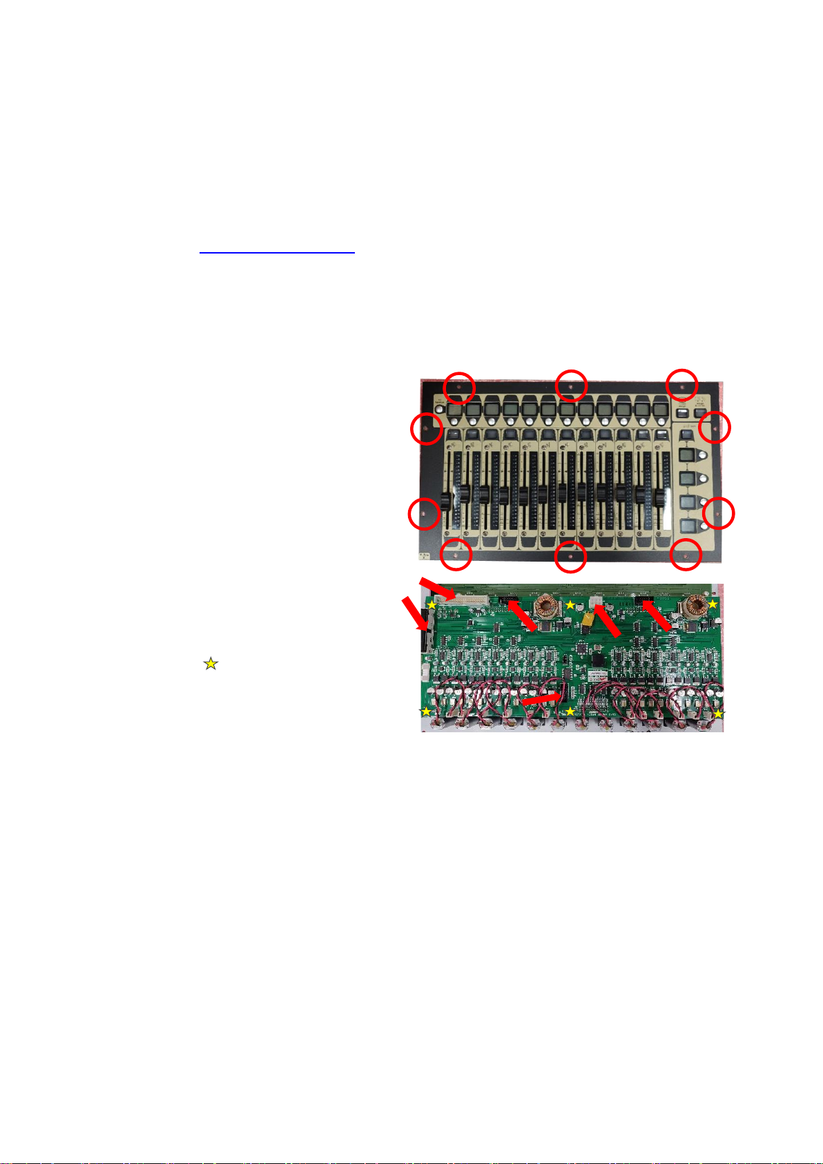
Replacing Faders
1. Power down the console, switch off the
PSU’s and connect your antistatic strap to
an appropriate earthing point.
2. Unscrew the fader panel (SD8 panel shown
opposite) with a screwdriver.
3. Carefully tilt the panel and disconnect the
cables to the PCB’s (indicated opposite with
arrows), and the connectors to the fader
motors.
4. Flip the panel back over and remove the
fader knobs and store them somewhere
safe.
5. Carefully unscrew the fader driver PCB
retaining screws (indicated above as
yellow stars ), store the screws
somewhere safe.
6. Flip the panel back over again and gently lift
the fader driver card away from the meters
card, being extra carefully as there are three
multipin connectors between the two PCB’s. Put this card to the side for now.
7. Unscrew the screws at the top and bottom of each fader and keep them safe, then flip the panel
over and remove the hex bolts and keep them safe.
8. Using the vacuum cleaner and the paintbrush, gently clean the panel, meters and the fader driver
PCBs, and the area inside of the console. Put the fader driver card somewhere safe.
9. If you are replacing the whole bank of faders (PA16033) then read section 9.1. If you are only
replacing single faders, skip to 9.2.
9.1.Remove the old meters and faders PCB and replace with the new PCB.
9.2.Using soldering tools, de-solder the faulty fader and discard it. Use the solder sucker to remove any
excess solder on the PCB solder pads. Carefully solder in the new fader.
10. Screw in the faders on the front of the panel, re-fit the fader driver PCB with the Hex bolts, re-plug
all connectors.
11. Place the fader panel back into the console, switch the console on and test the functionality of the
faders and buttons –the panel can now be screwed back into place.

TN 559 –Cleaning and replacing faders - All consoles Page 7
Cleaning Faders - Follow steps 1 –8 above
12. Use a clean paint brush and the vacuum cleaner to remove any loose dust and
dirt from the fader board, then use compressed air to dislodge any dust and dirt
from the inside of the fader assembly, then use the vacuum cleaner to remove
the dust and dirt. Repeat as necessary.
13. Lay the fader board on paper towels, place the thin nozzle applicator of the
degreaser along the fader track, give a quick spray and then move the fader up
and down.
14. Use the paper towel to clean up any excess mess, and use the compressed air to
dry the fader tracks.
15. Then spray some of the cleaner-lubricant spray (DeoxIT F5) along the fader slot and with the fader at
one end spray for no more than 1 second.
16. Move the fader up and down approximately 20 times and use the paper towel to wipe up any excess
or dirty liquid.
17. Repeat steps 11 - 13 for the remaining faders.
18. Re-install the faders, screw down the fader driver PCB, plug the faders
into the PCB, and carefully re-plug the connectors to the PCB’s. Place
the fader panel back into the console, switch the console on and test
the functionality of the faders and buttons –the panel can now be
screwed back into place.

TN 559 –Cleaning and replacing faders - All consoles Page 8
S-Series - S21 and S31
This section is for the cleaning and replacement of faders in S21 and S31 consoles only.
Part Numbers –see Appendix 1 –Fader Table for full details
•Input fader: 681-00177 Input fader with plug –S21, S31
•Master fader: 681-00178 Master fader with plug –S21, S31
Replacing Faders
1. Power down the console, switch off the PSU’s and
connect your antistatic strap to an appropriate
earthing point.
2. Unscrew the front panel with the 2mm Hex driver
and store these screws somewhere safe. There are
10 screws on the S31 and 8 screws on the S21.
3. Carefully lift the front edge of the panel and prop
the panel up so that you can reach inside. (see picture →)
4. Identify which faders will be replaced and remove the
fader knobs and disconnect the fader connector from the
fader driver PCB.
5. Use a 2mm Hex driver to remove the screws at the top and bottom of the first fader, store them
somewhere safe. Carefully remove the fader and place to one side.
6. Repeat the fader removal (steps 4 and 6) for the remaining faders to be replaced.
7. Using the vacuum cleaner and the paintbrush, gently clean the panel, PCBs, and the area inside of
the console.
8. Install the new faders, plug the faders into the PCB, carefully put the console panel back in place and
screw down.
9. Switch the console on and test the functionality of the faders and buttons.
Cleaning Faders - Follow steps 1 –6 above
10. When removing faders, remember which order they were in and label them if necessary.
11. Use the compressed air to dislodge any dust and dirt from the inside of the fader assembly, then use
the vacuum cleaner to remove the dust and dirt. Repeat as necessary.
12. Lay the fader on paper towels, place the thin nozzle of the cleaner-lubricant spray along the fader
slot and with the fader at one end spray for no more than 1 second.
13. Move the fader up and down approximately 20 times and use the paper towel to wipe up any excess
or dirty liquid.
14. Repeat steps 11 - 13 for the remaining faders.
15. Re-install the faders, screw down the fader driver PCB, plug the faders into the PCB, and carefully re-
plug the connectors to the PCB’s. Place the fader panel back into the console, switch the console on
and test the functionality of the faders and buttons –the panel can now be screwed back into place.

TN 559 –Cleaning and replacing faders - All consoles Page 9
Appendix 1 –Fader table
Part Number
Section
Found In
Number Required
Note
681-00200
Input
SD12, Q2, Q3
24 in SD12 and Q225
38 in Q338
681-00199
Master
SD12, Q2
2 in SD12
1 in Q225
Longer cable version of 681-00200
686-00030
Input
SD9, SD10,
SD11
24 in SD9
36 in SD10
24 in SD10-24
12 in SD11
686-00031
Master
SD10
1
SC-SD7-FADERI
Input & Master Lower
SD7Q, SD5Q
SD7, SD5
36 in SD7/SD7Q
37 in SD5/SD5Q
100mm Fader standard cable
SC-SD7-FADERL
Master Lower
SD7
2
100mm Fader long cable
SC-SD7-FADERM
Master Upper
SD7
12
60mm Fader standard cable
SC-SD7-FADERML
Master Upper
SD7
2
60mm Fader long cable
POT000181
Input & Master
SD8
37
Solder tabs
PA16033
Input
SD8
3 sections
WHOLE CARD 12 Faders
PA16038
Master
SD8
1 section
Master fader and meter
681-00177
Input
S21, S31
20 in S21
30 in S31
681-00176
Master
S21, S31
1
Longer cable version of 681-00177
This manual suits for next models
17
Table of contents
Other digico Recording Equipment manuals

Popular Recording Equipment manuals by other brands

Sharp
Sharp ER-A57R1 Service manual

Ensemble Designs
Ensemble Designs Avenue 7500 manual

Tascam
Tascam Portastudio 2488 Reference manual

Harman
Harman Soundweb London BSS BLU-800 installation guide

American Audio
American Audio Pocket Record User instructions

XtremeMac
XtremeMac MICROMEMO IPV-MIC-00 user manual


