digico SD10 User manual

SD10 Operation Manual
0-1
User Manual
UserManualVersionAforSoftwareVersions1.0.415+

SD10 Operation Manual
0-2
Copyright © 2011 Digico UK Ltd
All rights reserved.
No part of this publication may be reproduced, transmitted, transcribed, stored in a retrieval system, or translated into any
language in any form by any means without the written permission of Digico UK Ltd. Information in this manual is subject to
change without notice, and does not represent a commitment on the part of the vendor. Digico UK Ltd shall not be liable for any
loss or damage whatsoever arising from the use of information or any error contained in this manual.
All repair and service of the SD10 product should be undertaken by Digico UK Ltd or its authorised agents. Digico UK Ltd cannot
accept any liability whatsoever for any loss or damage caused by service, maintenance, or repair by unauthorised personnel.
Software License Notice
Your license agreement with Digico UK Ltd, which is included with the SD10 product, specifies the permitted and prohibited uses
of the product. Any unauthorised duplication or use of Digico UK Ltd software, in whole or in part, in print or in any other storage
and retrieval system is prohibited.
Licenses and Trademarks
The SD10 logo and SD10 name are trademarks, and Digico UK Ltd and the Digico UK Ltd logo are registered trademarks of Digico
UK Ltd. Microsoft is a registered trademark and Windows is a trademark of Microsoft Corp.
Digico (UK) Ltd
Unit 10
Silverglade Business Park
Leatherhead Road
Chessington
Surrey
KT9 2QL
England
Telephone: +44 (0)1372 845600
Fax: +44 (0)1372 845656
Email: [email protected]
WWW: http://www.digiconsoles.com
Manual Issue and Date: Issue A - March 2011 - For Version 1.0.415+ Software
Licence Agreement
"Product": SD10 software product produced by Digico UK Ltd intended for use on Target Platform identified below.
"Target Platform": Digico SD10 Digital Console system.
In return for the payment of the one-time fee, the Customer (identified at the end of this Agreement) receives from Digico UK
Ltd a licence to use the Product subject to the following terms and conditions.
1. The Product may be used without time limit by the Customer on the Target Platform.
2. The Customer must register the Product with Digico UK Ltd. Registering the Product is deemed an acceptance of the terms and
conditionsinthisagreement.
3. The Productanditslicence arenot transferable,andtheCustomer isnot permittedtoonward-licenseto anythird party. TheCus-
tomerindemnifies DigicoUK Ltdagainstany andallclaims andactionsarising fromthird partyuseof copiesofthe Productmadeby
theCustomer.
4. TheCustomeragreesnottoattempttodecompiletheobjectcodeoftheProductotherwisethanincircumstancesspecificallyprovided
forbylaw, andthenonly after consultationwithDigico UKLtd.
5. TheCustomeragrees notto use,orlicence theProduct foruse, withequipment otherthan theTarget Platform.
6. TheCustomer agreesnot tomodify theProductwithout theprior writtenconsentof DigicoUK Ltd.
7. ThisAgreementappliestoanyenhancementorupgradesthatmaybecomeavailablefortheProduct.
8. ThisAgreementdoes nottransfer anyright, title,or interest inthe Productto Customerexcept asspecifically setforth herein.
9. DigicoUKLtdreservestherighttoterminatethisAgreementuponbreach,inwhicheventCustomershallthereafteronlybeauthorised
tousetheProducttotheextentthatitscontractualcommitmentstothirdpartiesrequireand thenonlywheresuchcommitmentsrelate
touseoftheProductasauthorisedinthe foregoingprovisionsoftheAgreement.
LIMITED WARRANTY - Digico UK Ltd warrants for a period of 1 year from the date of purchase of the Product, the Product will reason-
ablyexecuteitsprogramminginstructionswhenproperlyinstalledontheTargetPlatform. Inthe eventthatthisProductfailstoexecuteits
programminginstructionsduringthewarrantyperiod,theCustomer'sremedyshallbetoreturnthe ProducttoDigicoUKLtdforreplace-
mentor repairatDigico UKLtdoption. Digico UKLtdmakes nootherexpress warranty,whetherwritten ororalwith respectof this
Product.
LIMITATIONOFLIABILITY-Exceptasotherwiseexpresslyprovidedbylaw,(a)theremediesprovidedabovearetheCustomer'ssole
andexclusiveremediesand(b)DigicoUKLtdshallnotbeliableforanydirect,indirect,special,incidental,orconsequentialdamages
(includinglostprofitwhetherbasedonwarranty,contract,tort,oranyotherlegaltheory.)
ThisagreementismadeundertheLawsof England.
LICENCE NO:..................... ..........................................................
REGISTRATION DATE:..... ..........................................................

SD10 Operation Manual
0-3
Contents
1.1 Introduction .............................................................................. .......1-3
1.2 Manual Overview ..................................................................... .......1-3
1.3 Before You Start ....................................................................... .......1-4
1.3.1 Worksurface Layout .............................................................1-4
1.3.2 Screen Assignment ..............................................................1-5
1.3.3 Layers and Banks.................................................................1-6
1.3.4 Using the Control Surface ...................................................1-6
1.3.5 The Assigned Channel .........................................................1-7
1.3.6 The Master Fader ..................................................................1-7
1.3.7 Other Centre Section Controls ............................................1-8
1.3.8 Channel Types ......................................................................1-8
1.4 Hardware Configuration.......................................................... .......1-9
1.4.1 Connections..........................................................................1-9
1.4.2 Audio I/O Panel....................................................................1-10
1.5 Configuring a Session .......................................................... .......1-13
1.5.1 Session Structure ...............................................................1-13
1.5.2 Assigning Faders to the Worksurface....................... .......1-14
1.6 Saving and Loading Sessions ............................................. .......1-15
1.7 Audio Sync .............................................................................. .......1-16
1.8 Routing Basics ..............................................................................1-17
1.8.1 Selecting Inputs & Outputs ................................................1-17
1.8.2 Ripple Channels .................................................................1-18
1.9 Presets..................................................................................... .......1-19
1.10 Naming Channels and Busses..................................................1-20
1.11 Channel Processing............................................................ .......1-21
1.11.1 EQ.......................................................................................1-21
1.11.2 Dynamics...........................................................................1-22
1.11.3Auxiliaries ..........................................................................1-22
1.12 The Matrix............................................................................. .......1-23
1.13 Control Groups .................................................................... .......1-24
1.14 Solo Setup............................................................................. .......1-25

SD10 Operation Manual
0-4
2.1 Introduction to Channel Types .............................................. .......2-2
2.2 Channel Input Setup - Common Elements ........................... .......2-2
2.2.1 Channel Strip InputArea ......................................................2-2
2.2.2 Channel Names ....................................................................2-2
2.2.3 Channel Safes.......................................................................2-3
2.2.4 Channel Settings ..................................................................2-3
2.2.5 Channel Solos ......................................................................2-5
2.3 Channel Output and Inserts - Common Elements............... .......2-6
2.3.1 Channel Strip OutputArea ...................................................2-6
2.3.2 Channel Strip InsertAreas ...................................................2-7
2.3.3 Console Output and Insert Routing ....................................2-7
2.3.4 Creating and Configuring FX Modules ...............................2-7
2.4 Input Channel Specific Functions ....................................... .......2-10
2.4.1 Trim and Track ....................................................................2-10
2.4.2 Input Routing ......................................................................2-10
2.4.3 Input Configuration ............................................................2-10
2.4.4 Output Routing ............................................................ .......2-11
2.4.5 Aux Busses and Assignable Controls ....................... .......2-11
2.4.6 Group Outputs ....................................................................2-12
2.4.7 Direct Outputs .....................................................................2-12
2.5 Group Channels Specific Functions................................... .......2-13
2.6 Aux Channels Specific Functions ..............................................2-13
2.7 Matrix Channels Specific Functions ..........................................2-14
2.8 Channel Signal Processing.................................................. .......2-14
2.8.1 Channel Filters (Input Channels Only) ..............................2-14
2.8.2 Channel EQ .........................................................................2-14
2.8.3 Channel Dynamics .............................................................2-16
2.9 LCD Functions...............................................................................2-17
2.9.1 Introduction to LCD Functions..........................................2-17
2.9.2 Solo......................................................................................2-17
2.9.3 Solo Choice.........................................................................2-17
2.9.4 GANG ...................................................................................2-17
2.9.5 JOIN CG ...............................................................................2-18
2.9.6 Assign Faders .....................................................................2-19
2.9.6 Unassign Faders ................................................................2-19
2.9.8 Copy Bank From.................................................................2-20
2.9.9 Copy Bank To .....................................................................2-20
2.9.10 Clear Bank.........................................................................2-20

SD10 Operation Manual
0-5
3.1 System Menu............................................................................ .......3-2
3.1.1 Diagnostics ...........................................................................3-2
3.1.2 Oscillator ...............................................................................3-2
3.1.3 Security .................................................................................3-2
3.1.4 Clear Over Indicators............................................................3-4
3.1.5 Overview Clear Screen.........................................................3-4
3.1.6 Keyboard Help ......................................................................3-4
3.1.7 F10: Reset FX........................................................................3-4
3.1.8 F11: Reset Engine ................................................................3-4
3.1.9 F12: Reset Surfaces .............................................................3-4
3.1.10 Set Date & Time ..................................................................3-4
3.1.11 Shutdown ............................................................................3-4
3.2 Files Menu................................................................................. .......3-5
3.2.1 Session Structure .................................................................3-5
3.2.2 Load Session ........................................................................3-7
3.2.3 Save Session ........................................................................3-7
3.2.4 Save As New File ..................................................................3-7
3.2.5 Load Presets .........................................................................3-8
3.2.6 Save Presets .........................................................................3-9
3.2.7 Global Set To Defaults ..........................................................3-9
3.2.8 Session Notes.....................................................................3-10
3.2.9 Session Report ...................................................................3-10
3.3 Layout Menu........................................................................... .......3-11
3.3.1 Fader Banks................................................................. .......3-11
3.3.2 Channel List ........................................................................3-12
3.3.3 Transport Control ...............................................................3-12
3.4 Snapshots Menu .................................................................... .......3-13
3.4.1 Storing a Snapshot.............................................................3-13
3.4.2 Recalling a Snapshot .........................................................3-14
3.4.3 Replacing a Snapshot ........................................................3-14
3.4.4 Editing Multiple Snapshots ................................................3-14
3.4.5 Moving a Snapshot.............................................................3-15
3.4.6 Renaming a Snapshot........................................................3-15
3.4.7 Renumbering Snapshots...................................................3-15
3.4.8 Deleting a Snapshot ...........................................................3-15
3.4.9 Snapshot Undo...................................................................3-15
3.4.10 Snapshot Groups .............................................................3-15
3.5.11 Global Recall Scope.........................................................3-17
3.5.12 Individual Snapshot Recall Scope .................................3-17
3.5.13 Snapshot Crossfades ......................................................3-18

SD10 Operation Manual
0-6
3.5.14 Snapshot Recall Times ....................................................3-19
3.5.15 Introducing Snapshots and MIDI.....................................3-19
3.5.16 Snapshot Control by MIDI ................................................3-19
3.4.17 MIDI Devices......................................................................3-20
3.4.18 MIDI Program and MIDI List..............................................3-20
3.4.19 GPOs and Snapshots.......................................................3-21
3.4.20 Surface Offline & Snapshot Editing ................................3-22
3.4.21 Snapshots and Transport Automation............................3-22
3.4.22 Auto Update ......................................................................3-22
3.5 Options Menu ......................................................................... .......3-23
3.5.1 Surface ................................................................................3-23
3.5.2 Faders..................................................................................3-24
3.5.3 Solo......................................................................................3-24
3.5.4 Disable.................................................................................3-25
3.5.5 Brightness...........................................................................3-25
3.5.6 Meters ..................................................................................3-25
3.5.7 Session................................................................................3-26
3.5.8 Status...................................................................................3-26
3.6 Matrix Menu.......3-28
3.6.1 The Matrix Panel .................................................................3-28
3.6.2 Matrix Presets .....................................................................3-29
3.7 Graphic EQs Menu .......................................................................3-29
3.7.1 Graphic EQ Panel................................................................3-29
3.7.2 Ganging Graphic EQs.........................................................3-30
3.7.3 Graphic EQ ALLButton ......................................................3-30
3.7.4 Graphic EQ Presets ............................................................3-30
3.8 Solos Menu............................................................................. .......3-31
3.8.1 The Solo Panel....................................................................3-31
3.8.2 The No Solo Setup Display ................................................3-32
3.8.3 Assigning Solo Busses to Worksurface Controls ...........3-33
3.8.4 Solo Outputs Routing................................................. .......3-33
3.8.5 Headphone Outputs ...........................................................3-33
3.9 Setup Menu....................................................................................3-34
3.9.1Audio I/O ..............................................................................3-34
3.9.2 Port Selection......................................................................3-34
3.9.3 Port Hardware Configuration.............................................3-34
3.9.4 Port Control.........................................................................3-35
3.9.5 The Socket Display.............................................................3-35
3.9.6 Socket Conforming ............................................................3-35

SD10 Operation Manual
0-7
3.9.7 Group and Socket Names ..................................................3-36
3.9.8 Socket Options ...................................................................3-36
3.9.9Audio Sync ..........................................................................3-36
3.9.10 Timecode & Transport......................................................3-37
3.9.11 Macros ...............................................................................3-37
3.9.12 The Macro Editor ..............................................................3-38
3.9.13 Talkback ............................................................................3-39
3.10 Screen and Light Brightness ............................................. .......3-40
4.1 Network and Mirroring ............................................................ .......4-2
4.1.1 Network Configuration.........................................................4-2
4.1.2 Mirroring for the first time.....................................................4-2
4.2 Multi-console Setups............................................................... .......4-4
4.2.1 FOH and Monitors sharing a stage rack .............................4-4
5.1 Troubleshooting ...................................................................... .......5-2
5.1.1 Starting the console .............................................................5-2
5.1.2 Audio not passing on certain channels ..............................5-2
5.1.3 Snapshots not recalling as expected..................................5-2
5.1.4 Snapshots not inserting as expected .................................5-2
5.1.5 Assigning console controls .................................................5-2
5.1.6 Console controls not affecting the audio ...........................5-2
5.1.7 Channels not appearing on the worksurface.....................5-3
5.1.8 No signal from the Solo buss ..............................................5-3
5.1.9 Signal from the Solo buss when nothing is soloed ...........5-3
5.1.10 External keyboard ..............................................................5-3
5.1.11 Resetting the console.........................................................5-3
5.1.12 Talkback ..............................................................................5-3
5.1.13 Meters ..................................................................................5-3
5.1.14 Console lighting..................................................................5-3
5.1.15 Joystick not responding as expected...............................5-3
5.1.16 Features not yet implemented ...........................................5-3
5.1.17 Diagnostics .........................................................................5-4

SD10 Operation Manual
0-8

Chapter 1 - Getting Started
1-1
SD10 Operation Manual
Chapter 1:
Getting Started

Chapter 1 - Getting Started
1-2

Chapter 1 - Getting Started
1-3
1.1 Introduction
The Digico SD10 consists of a worksurface with an onboard audio engine and a range of onboard inputs and outputs. This can be
connected to multiple Input/Output Rack Units by MADI links or optical fibre (optionally) which carry all the audio input and output
signals.
The console worksurface consists of 3 sections that can control 96 input channels (12 of which can be stereo with no loss of
channel count), 12 VCAs, up to 48 aux/group busses (plus Master buss configurable as LCR, and solo buss), a matrix of 16
inputs and 12 outputs, 24 onboard graphic EQs and 10 onboard stereo effects.
The left section has 12 assignable faders and 12 sets of assignable encoders and switches.
The centre section has, a touchscreen, 12 assigned encoders, 12 assignable faders, 12 sets of assignable encoders and
switches, a full set of channel processing controls and a master fader.
The right section has 12 assignable faders, 12 sets of assignable encoders and switches and controls for monitoring, head-
phones, talkback, macros and snapshots.
Any of these worksurface sections can be assigned to the centre touchscreen.
Multiple console setups can provide:
Front of House and Monitoring with shared stage racks and gain tracking.
Remote control of a console from a laptop computer.
Optional extras include Waves plug-ins and Broadcast mode (Broadcast mode includes features such as surround busses, mix
minus busses, multi-input channels, backstop PFL, auto PFL, fader start GPOs and expanded monitoring options). See the Appen-
dices for details of these options.
1.2 Manual Overview
- Chapter 1 provides an overview of the desk, and describes some of the basic operating principles which the user
will need to understand in order to run the desk.
- Chapter 2 describes the functions of the different channel types.
- Chapter 3 describes the master section of the desk, focusing on the various menus in the Master screen.
- Chapter 4 describes network, mirroring and multi-console setups
- Chapter 5 is a guide to troubleshooting
- Appendices are provided for the Waves plug-ins, Broadcast mode options, and Optocore operation.
The following typographical conventions are used in this manual:
Bold type is used to indicate that the text is an exact copy of the labelling either on a screen or on the worksurface.
An arrow bracket (>) is used to indicate a sequence of button pressing. For example, Layout > Fader Banks indicates that the
Fader Banks button is accessed by first pressing the Layout button.

Chapter 1 - Getting Started
1-4
1.3 Before You Start
There are certain general operating principles and terms that should be understood before continuing to use this manual.
Please read this chapter carefully before proceeding.
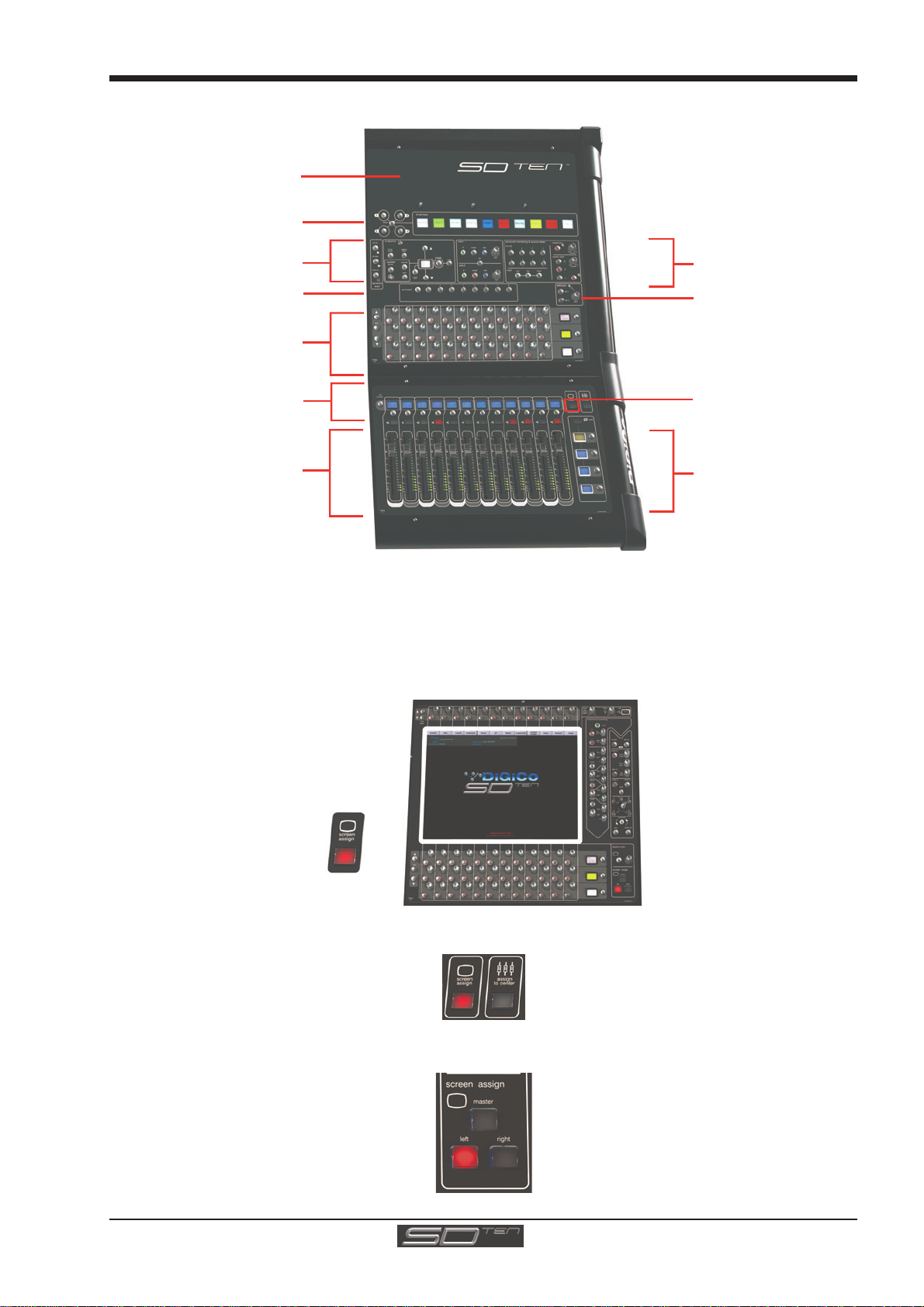
1.3.1WorksurfaceLayout..............................................................
Centre Section
Input Gain and Phase
A
ssignable Rotaries and Switches
A
ux / Pan / Dynamics/FX Controls
Mute and Channel Select Buttons
Channel Faders
ALT Input Switch
Undo/Redo
2nd Function Button
Option/All Button
USB Port
Light
Controls
Assignable Rotary Scrollers
Channel Processing:
High and Low Pass Filters
4 Band Dynamic Parametric EQ
Dynamics Thresholds & On / Off
Channel Inserts A & B On/Off
Direct Out On/Off
Joystick Panning
Touch/Turn Controls
Touchscreen
Left/Right/Master ScreenAssig
n
Snapshot Previous/Next
Centre Section ScreenAssign
Bank Select Buttons
& Master Fader/Mute
Left Section
Laptop Area for Optional
Remote Control
A
ssignable Rotaries and Switches
Aux / Pan / Dynamics Controls
Mute and Channel Select Buttons
Channel Faders
Left Section Screen Assig
n
Bank Select Buttons
Chapter 1 - Getting Started
1-5
Right Section
A
ssignable Rotaries and Switches
Aux / Pan / Dynamics Controls
Macros
Space for Keyboard
& Trackball
Snapshot Automation
Channel Faders
Right Section Screen Assig
n
Talkback
Monitoring
Bank Select Buttons
Mute and Channel Select Buttons
Smart Keys
1.3.2ScreenAssignment...............................................................
The SD10 touchscreen is used to access many of the console's functions.
There are 4 possible views that can be seen on this screen - Left section - Centre section - Right section - Master screen
Each console worksurface section has its own Screen Assign button which, when pressed, will allow the channels in that
section to be viewed on the screen and controlled by the Centre section's Channel Processing controls such as EQ and Dynam-
ics. When the button is lit, that section is assigned to the screen.
When a section has been assigned to the screen all of the controls in the upper centre section are also assigned.
The Left and Right worksurface sections also each have a button labelled Assign To Centre which will allow all of the Centre
sections controls including faders, mutes and solos to control the bank which has been selected in the Left or Right sections..
There are also additional buttons in the centre section which can assign the Left and Right sections to the screen and a Master
button which allows you to view the Master screen. The Master screen gives access to many setup and other functions which
are not directly related to the console's channels.

Chapter 1 - Getting Started
1-6
1.3.3 Layers and Banks .................................................................
The SD10's worksurface is divided into Layers and Banks. Each Bank contains twelve channels, and the channels which are
currently active on the control surface are defined using the fader bank and bank layer buttons to the right of the Channel Strip
section’s faders:
S
elect a Layer
S
elect a Bank
A ‘bank’ is a set of twelve faders, and a ‘layer’ contains up to four ‘banks’. There are two ‘layers’ in each section of the desk,
allowing up to 144 channels to be accessible on the worksurface.
Pressing the bank layer button, located above the fader bank buttons, toggles between layers.
To access a bank of faders within that layer, press the appropriate fader bank button. To switch all three sections of the
console to the same bank level, press and hold one of the fader bank buttons.
The position of the banks on the worksurface is defined in the Layout > Fader Banks panel. By default, the Input channels will
be assigned to Layer 1 on the left and right sections of the console. The different output channels will be assigned to Layer 1 on
centre section. Control Groups will also be assigned to the centre section. These bank assignments can be customised by the
user and saved in a session at any time.
1.3.4 Using the Control Surface ....................................................
There are two main ways in which all of the functions of the SD10 are accessed:
1. The touchscreen display, which can be controlled directly using a finger, or by using the keyboard and mouse
2. The physical encoders, switches and faders.
Note that when touching the screen directly, you may find it easier to use a finer point than your finger.
However, in order to prevent damage to the screen, it is important that you only use devices specifically
designed for touching screens (such as a pda stylus), and that you never press down hard on the screen.
A number of functions can be accessed in different ways, allowing users to operate the console using whichever interface they
prefer. This manual will describe accessing on-screen functions by touching the screen directly and not by using the mouse.
All of the physical controls found in the centre section are described in full within the relevant section of the manual and many
require no further introduction. The Master screen has a row of grey buttons which are used to access a range of configuration
displays. Pressing these buttons opens either a further drop-down sub-menu or a pop-up display. If a drop-down menu is
opened, pressing on one of its entries will open a pop-up display. The buttons lighten to indicate that their sub-menu or pop-up
display is open. A number of the buttons within each pop-up display generate further pop-ups.
The buttons within the pop-ups are coloured grey when their function is inactive, generally switching to a lighter shade of the
pop-up background when their function is active. Pressing on a text box opens a numeric or QWERTY keypad which can be
operated directly by pressing the screen or via the console’s external keyboard.
Pop-ups are closed by pressing the box in the top right-hand corner of the pop-up, marked CLOSE or CANCEL (or by pressing
CAN on keypad pop-ups).
To the right and below the Master screen is a single encoder marked touch-n-turn (shown below). This is used to access some
of the rotary and switch controls within the Master screen. To assign the touch-n-turn encoder to a particular on-screen pot,
touch the pot to be assigned. You will notice that a coloured ring appears around the on-screen pot, indicating that it is assigned
to the touch-n-turn encoder/switch.
Chapter 1 - Getting Started
1-7
1.3.5 The Assigned Channel .........................................................
One of the channels in the Channel Strip panel is displayed in gold, indicating that it is currently the Assigned Channel. This means
that it has been assigned to the worksurface controls and can be configured in detail, as described below. To Assign a channel,
touch anywhere in the channel on the screen (except the Aux Send area).
Once a channel is Assigned, all of the controls for that channel which are not displayed within the channel strip itself can be
accessed via secondary pop-ups, displayed by touching inside the relevant area of the channel. These pop-ups include controls
such as input and output routing and signal processing parameters.
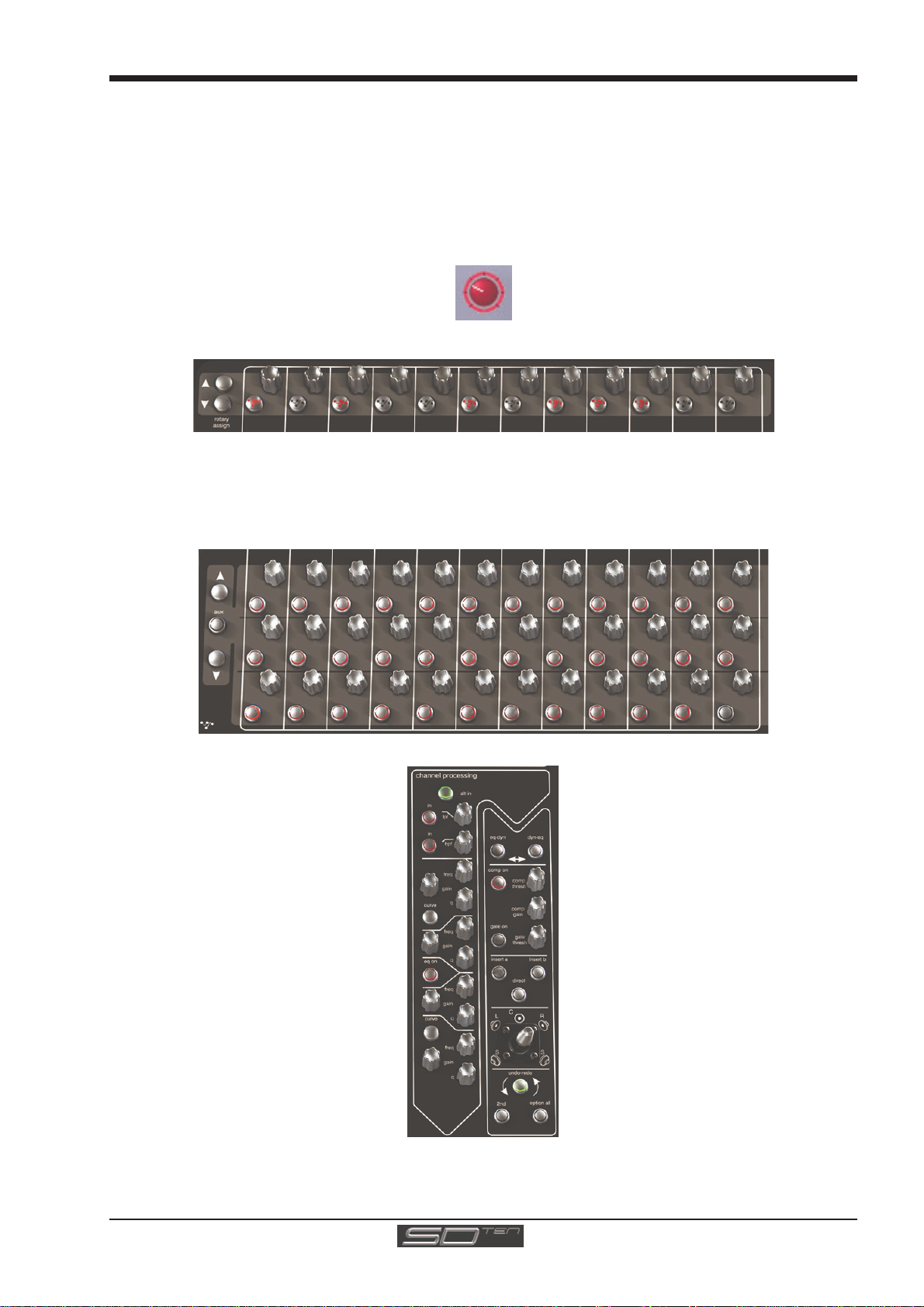
A number of the physical rotary encoders on the control surface can be assigned to different on-screen pots. In order to ensure
that it is clear which function is assigned to which encoder, the assigned on-screen pot will have a coloured ring around it.
The twelve encoders and buttons immediately above the touchscreen refer to the channels with which they are aligned. These
controls are concerned with the channel input, located at the top of the Channel Strip panel.
The three rows of encoders and buttons immediately below the touchscreen also refer to the channels with which they are
aligned. Normally, the upper two rows control the level and on/off status of the two highlighted aux sends, but can have a number
of functions assigned to them. Touching on an aux send on the screen will assign that aux and the ones immediately below it to
the aux encoders. Six of the aux sends can be displayed in the Channel Strip panel at any one time. If more than six aux sends
have been created in the session, the scroll buttons outside the bottom left-hand corner of the screen can be used to scroll the
display through the remaining auxiliaries. The third row is assigned to channel pan by default.
The controls to the right of the Channel Strip panel allow the Assigned channel to be adjusted:
1.3.6 The Master Fader..................................................................
By default, the master fader is assigned to the master group output, which is the lowest stereo group output by default. In
addition, the master fader can be assigned to the solo buss output.

Chapter 1 - Getting Started
1-8
1.3.7 Other Centre Section Controls.............................................
To the left of the Channel Strip panel are more channel controls: When pressed, the 2nd function button allows access to
different parameters:
1) Stereo Aux Pan and Pre/Post switching
2) Hard Mute of a channel
3) Fine adjustment of Delay settings on output channels
The Option/All button has 2 main functions:
1) When pressed and released, any channel that is a member of a gang will be temporarily isolated from that gang.
2) When pressed and held, any parameter that is adjusted on a single channel will also be adjusted in the same way
on all of the channels in that bank
1.3.8 Channel Types ......................................................................
The signal flow of the SD10 is best understood in terms of the four channel types contained within it, shown below. Each channel
type offers full signal processing capabilities. As a summary, the four channel types are as follows:
- Input channels bring signals into the console to be mixed and sent to aux and group busses.
- Aux channels send a variety of mixes of the Input channels to the Aux outputs, mainly for use as monitor mixes and FX
sends.
- Group channels mix groups of input channels together, to feed the buss outputs or the output matrix.
- Matrix channels send the outputs of the matrix to the console’s main outputs (Optionally).
Note there is also a TB In channel which is its own channel type. This is described in the Talkback section of the Master
Screen chapter.
The Group channels, Aux channels and Matrix channels are all referred to as output channels. While the Aux and Matrix channels
are the channel types most commonly routed to outputs, all four channel types can be routed directly to outputs.
Input Module - Touch to Expand
Analogue Gain/Digital Trim
Phase - Gain Tracking
Main/Alt Input Select
Inputs
Insert A Routing & On/Off
HPF/LPF
4 Band EQ
Touch To Expand
Dynamics
Touch To Expand
Insert B Routing & On/Off
AuxSends (
)
Metering (Output Channels)
C
omponent unfolding (Group, Aux)
Talkback (Aux)
Input Channels -
Touch to Assign Rows
Channel Pan
Mute & Hard Mute
Channel Label
Routing Module - Touch to Expand
Gang & Safe Indicators
Groups
Auxes
Matrix
Channels are laid out in banks of 12 on the console worksurface and can be identified by their colour: Light-blue for Input chan-
nels, red for Group channels, purple for Aux channels and blue-green for Matrix channels.
By default, the Input Channels will be assigned to Layer 1 on the left and right sections of the console. Output channels (Groups,
Auxes and Matrices) and Control Groups will be assigned to the centre section. These bank assignments can be customised by
the user and saved in a session at any time.
Holding any bank or layer button down for a couple of seconds will switch all 3 worksurface sections to the same bank level or
layer.
The controls on each different type of output channel are similar but an input channel has a number of additional features.

Chapter 1 - Getting Started
1-9
1.4 Hardware Configuration
1.4.1Connections ..........................................................................
Detailed information on the various systems of connection is provided in the relevant Appendix but the following diagram provides
an overview of a single console/single rack setup.
All connections should be made before switching on the console and racks.
The console and rack each have dual redundant power supplies and both should be switched on at all times. After switching on
the console the software will be launched automatically and the state of the worksurface and settings should be the same as
when it was last Shut Down.
To Shut Down the console press the System>Shut Down button and wait until you receive a message saying that it is safe to
switch the power off.
The SD10 worksurface has 8 analogue I/O and 8 AES I/O on its rear panel and remote I/O racks are available in several formats.
These racks can be connected to the console with 2x 100M high specification 75Ohm coaxial cables fitted with BNC connectors,
or optical fibre.
In normal operation the MADI connections should be as follows (see diagram below):
Rack MAIN MADI IN connected to the console MADI 1A OUT
Rack MAIN MADI OUT connected to the console MADI 1A IN
Note - Optionally, a second set of MADI cables can be connected to provide MADI redundancy from the
rack's AUX MADI ports to the console's MADI 1B ports
The console's MADI Port 2 can be connected to a MADI recorder or a second DiGiCo Rack or console.
Optional Remote Control
Laptop connection with
E
thernet Crossover Cable
STANDARD CONNECTION WITH MADI
MAIN MADI
IN MAIN MADI
OUT
MADI 1A OUT
MADI 1A
MADI INPUTS
MADI OUTPUTS
MADI 1BMADI 2AMADI 2B
MADI IN
MADI 1A IN
MADI OUT
Remote I/O Rack
AUX MADI
IN AUX MADI
OUT
MADI 1B OUT MADI 1B IN
Optional
Redundant
MADI
Connection
SD10 Rear Panel MADI Connections
MADI 2A IN
MADI 2B OUT
Optional
MADI Recorde
r
or
Second I/O Rac
k
Chapter 1 - Getting Started
1-10
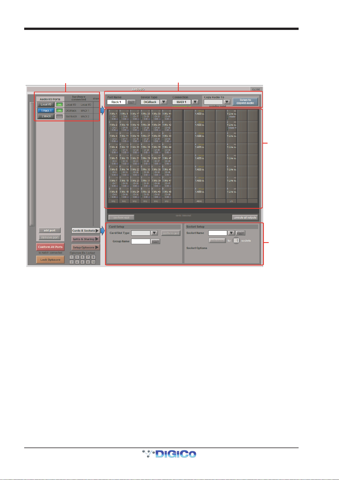
1.4.2 Audio I/O Panel.....................................................................
The Audio I/O window is used to configure the physical I/O connected to the SD10, including configuring and naming the sockets
of the cards installed in racks, and the setting of Pads and phantom power.
Local I/O : The SD10 provides local audio I/O in the rear of the console. These operate independently of connected racks.
To access the SD10 Audio I/O Setup touch Setup>Audio I/O on the Master Screen
The Audio I/O window that opens is divided up into the following sections:
Port selection
Port properties
Graphic of
connected
rack
Options display for:
Cards & sockets,
Splits & Sharing,
or Optocore setup
.
(Defined by buttons
to the area’s left)
The top-left corner of the window shows the ports. Each port relates to an available physical audio connection (Local IO, MADI
Ports or optional Optocore connections).
The top section to the right of this contains the controls relating to the ports. When a port is selected, this section changes to
reflect the status of the selected port, and allows it’s configuration to be changed as required.
Below the port controls is a graphical representation of the rack configuration connected to the selected port. Depending on the
port selected, the graphic will change, showing the available physical I/O. Each small “square” on the image represents a single
physical audio connection or socket, with these arranged in columns or rows, representing I/O cards in racks, or the local I/O on
the back of the console.
The section below the graphical rack picture displays one of three things, as selected by the coloured buttons to its left:
- Select Cards &Sockets to configure the cards or slots and sockets, including
custom naming, phantom power and pad selection.
- Select Splits &Sharing to configure the sharing of card control between consoles
and split outputs on an SD Rack
- Select Setup Optocore to configure optocore connections (See the separate
Optocore v221 manual)
The local I/O configuration is fixed, so no hardware changes are possible. You can, however, change the Port Name, the Group
Names and the Socket Names (the name of each physical connector on a card).
Note that Setup Optocore only applies (and only appears) if the session is setup to use Optocore version 221.

Chapter 1 - Getting Started
1-11
RackConnections
With a Rack selected in the left hand port selection list, the window will change to look something like the image below, depending
on the cards installed in the connected rack. The graphic shows the 14 available cards/slots, 7 input & 7 output.
In order to use the rack, the on-screen contents of the rack must match the cards physically installed in the rack connected. There
are two ways of achieving this :
Manual Conforming of Rack:
Select each card (column) and manually select the appropriate card in the Card/Slot Type drop down menu in the lower section of
the window (displayed when the Cards & Sockets button towards the bottom-left is selected). Once the correct card type is
selected, the Label at the bottom the selected card will turn green, indicating the card type matches the card installed in the rack. If
the Card Type name is Red, then there is a mismatch, and the error should be corrected by selecting the correct card type.
AutomaticConforming:
There are three levels of automatic conforming:
- globally, using the red Conform All Ports button in the bottom left of the window;
- on a rack-by-rack basis, using the conform rack button just below the rack view
section of the window;
- on a card-by-card basis, by selecting a socket from the card in the graphical display
and using the conform card button next to the Card/Slot type button selector in the
lower section of the window. (Note that the Cards & Sockets button towards the
bottom-left should be selected)
Pressing any of these buttons will correctly select the card types for the range in question. Once complete, all of the Card Labels
beneath each slot should turn green.
Copying Audio and Listening to Copied Audio (External Recorder Setup)
Any incoming MADI or Optocore stream can be copied to any MADI Output by selecting the incoming Port in the Ports list (in the top
left of the panel) and selecting the MADI output in its Copy Audio To drop-down menu (in the top right of the panel). The console
will send the 56 channel MADI stream to the selected output.
In addition, by connecting a MADI return from the external device (the playback from a recorder, for example) to its corresponding
MADI input on the console, it can be monitored in the same channels as the original source material: press the Listen to Copied
Audio button. Press the button again to return to normal monitoring.

Chapter 1 - Getting Started
1-12
StandardMADIConnections
If you have a standard MADI connection (not a DiGiCo Rack) to your SD10, you can set the SD10 to display the MADI with generic
signal names, i.e. MADI 1, MADI 2.. etc. through to MADI 56 instead of the usual rack style names. The naming does not affect the
signal, but makes routing signals easier.
Edit the Port Name here.
Eg. Stage Rack, Local Rack etc...
Analogue Line Out
Socket with -10db Pad
Select Card Type manually or
usingAuto-Conform function,
and edit Group Name
Selected Socket Properties
Edit Name and Socket options.
A
uto Conforming for all ports,
i
ndividual racks,
o
r individual cards
Select the contents of the bottom-right
corner of the Audio IO window
Select the port to be configured
Consoleto Console routing
If two DiGiCo consoles are connected together, it is possible to route audio between them.
Splits & Sharing
In a multi-console system where Racks are connected with MADI and shared between two DiGiCo Consoles, only one of the
consoles can take control of the rack, with respect to Gain, Phantom Power and Pads. To overcome this, it is possible to place the
SD10 into one of 3 states of operation; Isolate, Receive Only or Full Control.
Sharing is configured in the bottom right-hand corner of the window when the Splits & Sharing button is selected:
These three states can be set individually in the right column), on a per-rack basis (middle column), or globally for all shared racks
(left column).
Isolate : The SD10 will not communicate with the rack and therefore any adjustment of input gain or +48V switch will have no
effect on the rack settings
Receive Only : The SD10 will receive the rack’s existing settings but will not be able to control the gain etc on the racks.
Full Control : The SD10 will send its settings to the racks and change them accordingly.
Table of contents
Other digico Recording Equipment manuals


