BURL B80-BMB3 MOTHERSHIP User manual

B80-BMB3
MOTHERSHIP
BMB3 Rev C Rom 1
Quick Start Guide
Section 1: Getting Started
Section 2: Dante Quick Start
Section 3: Dante Clocking
Revision 1.6 March 29, 2018

Image 1:Locating the H8 Header on BMB3 Motherboard: From the rear of the chassis,
BMB3 is on the far left. The H8 Header is highlighted. In this example, jumpers are on 1 and 3.
1
SECTION 1
1. GETTING STARTED
1.1 Register
Please register all serial numbers for your B80 MOTHERSHIP chassis, all Daughter Cards,
and BP-300.
You must register to activate your warranty! Please visit: www.burlaudio.com/register.
1.2 Check Jumper Settings On BMB3
The B80 MOTHERSHIP is fully modular, accommodating a wide variety of I/O needs. Jumper
settings on the BMB3 Motherboard allow for dierent I/O routing possibilities.
1. Find H8 on the BMB3 Motherboard, as shown in Image 1 below.
2. Use Examples A through D (on pages 2 and 3) to determine which setting to use based
on your conguration.
3. See Channel Mapping for Jumper Settings charts on page 4.
4. Jumper positions 1 and 2 determine the INPUT channel mapping, this allows you to set
the conguration for each card slot in the MOTHERSHIP.
(Congurationspossible:4Ch.perslot/8Ch.perslot/8and4Ch.perslot).
5. Jumper positions 3 and 4 determine the OUTPUT channel mapping, this makes it so you
can set where our OUTPUTS start in the MOTHERSHIP chassis.
(Outputcanstartinslots3,5&7)
6. Jumper positions 5, 6 and 7 have no function.
(Jumperscanbekepthereforsafekeepingwhennotinuse)
7. Jumper 8 is for use with the B16 MOTHERSHIP chassis, and should not be used with
the B80 MOTHERSHIP chassis.

2
SECTION 1
Image 5: Jumpers on 6 and 7
for use with BAD4 and BDA8.
Jumper positions 6 & 7 have
no function. Jumpers may
be kept here for safe keeping
when not in use. In this
example, there are 4 inputs per
slot and output Ch.1 starts in
slot 7.
Image 4: This is an example of a 24 in x 32 out
MOTHERSHIP with BAD4’s and BDA8’s. In this
example, inputs 1-4 are found in slot 1, outputs 1-8
are found in slot 7.
EXAMPLE A: JUMPERS ON 1 AND 3 (FACTORY SETTING)
BMB3 jumper settings for a 40 in x 40 out system using BAD8
and BDA8 Daughter Cards
EXAMPLE B: NO JUMPERS ON 1 - 4 (STORED ON 6 AND 7)
BMB3 jumper settings for a 24 in X 32 out system using BAD4
and BDA8 Daughter Cards
Image 3: Jumpers on 1
and 3 for use with BAD8
and BDA8. Jumper 1
enables 8 channels per
slot for inputs. Jumper 3
assigns output Ch. 1 to
slot 5.
Image 2: This is an example of a 40 in x 40 out
MOTHERSHIP with BAD8 and BDA8 Daughter Cards.

3
SECTION 1
Image 9: Jumpers on 1 and 4
for use with BAD8 and BDA8.
Jumper 1 enables 8 Ch. per
slot for inputs. Jumper 4
assigns output Ch. 1 to slot 3.
Image 8: This is an example of a 16 in x 64 out
MOTHERSHIP with BAD8 and BDA8 Daughter Cards.
EXAMPLE C: JUMPERS ON 2 AND 3
BMB3 jumper settings for a 32 in x 32 out system using BAD8, BDA8, BAES4
and BCLK Daughter Cards
EXAMPLE D: JUMPERS ON 1 AND 4
BMB3 jumper settings for a 16 in X 64 out system using BAD8
and BDA8 Daughter Cards
Image 7: Jumpers on 2 and
3 for use with for BAD8’s,
BAES4, and BDA8’s. Jumper
2 enables 8 Ch. per slot for
inputs for slots 1-4. and 4
Ch. per slot for slots 5-10.
Jumper 3 assigns output Ch.
1 to slot 5.
Image 6: This is an example of a 32 in x 32 out
MOTHERSHIP with BAD8’s, BDA8’s, BAES4, and
BCLK Daughter Cards.

4
SECTION 1
CHANNEL MAPPING FOR JUMPER SETTINGS
JUMPERS 1 AND 2: INPUTS
CHANNEL MAPPING FOR JUMPER SETTINGS
JUMPERS 3 AND 4: OUTPUTS
Note: To purchase blanks for empty MOTHERSHIP slots, contact your BURL dealer!
For more information on installing Daughter Cards, please go to
www.burlaudio.com/b80-quick-start-video
1.3 Install Daughter Cards
i.
ii.
iii.
Image 11:
Attaching ribbon cable
to front panel.
Image 10:
Inserting Daughter Card
into the card guides.
i. ii. iii. iv. v. vi.
3
iv.
v.
vi.

5
SECTION 1
1.4 Install Vents
Install the 1U vents above and below the B80 chassis. The MOTHERSHIP MUST run with proper
ventilation.
Failure to properly vent the MOTHERSHIP chassis above and below may cause
failure, and will void the warranty.
CONTINUE TO:
SECTION 2
DANTE QUICK START (page 6)
SECTION 3
DANTE CLOCKING (page 12)
Image 12: B80 MOTHERSHIP with 1U vents above and below for proper airow.

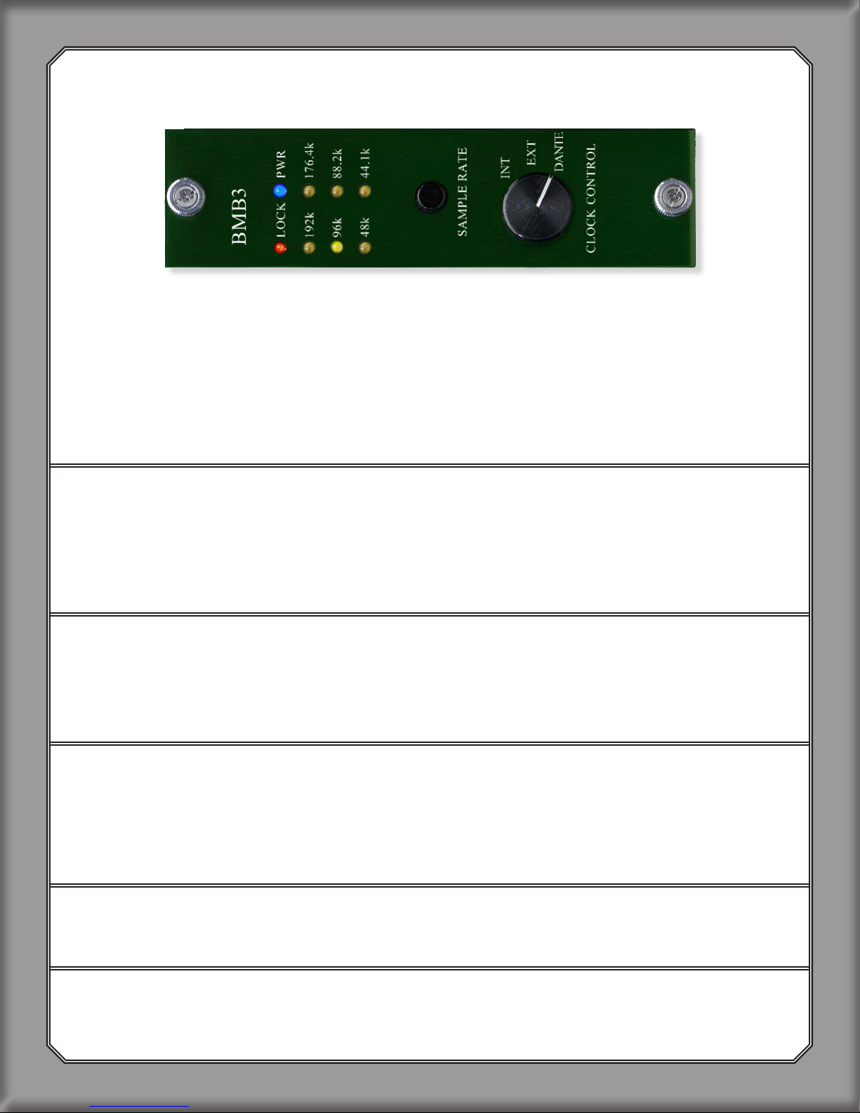
Each Ethernet port can handle:
• 64 ch. at 44.1 kHz or 48 kHz
• 32 ch. at 88.2 kHz or 96 kHz
• 16 ch. at 176.4 kHz or 192 kHz
2. DANTE QUICK START
YOU WILL NEED:
•B80 Mothership with BMB3 Motherboard
•Dante
PCIe Card
- OR - Dante Virtual Sound Card (DVS)
• Gigabit Ethernet Switch
• Cat6 Ethernet Cables
• Optional:AdditionalBKII-BMB3cardwilldoublethechannelcount
• Dante Controller
2.1 Install PCIe Card In CPU Or Download And Install Dante
Virtual Soundcard (DVS)
For optimal performance, the B80-BMB3 Dante MOTHERSHIP should be used with a Dante
PCIe Card
.
FocusriteRednetPCIe,RednetPCIer,orYamahaDanteAccelerator PCIe Cards are
recommended.
When latency is not an issue, (live recording, archiving, etc) Dante Virtual Sound Card (DVS)
may be used in place of a
PCIe Card
. DVS will add 4ms of latency in and out, for a total round
trip of 8ms. Total latency of the system will include the latency of the converter chips and the
DAW. We recommend a
PCIe Card
for all applications.
To download DVS: https://www.audinate.com/products/software/dante-virtual-soundcard
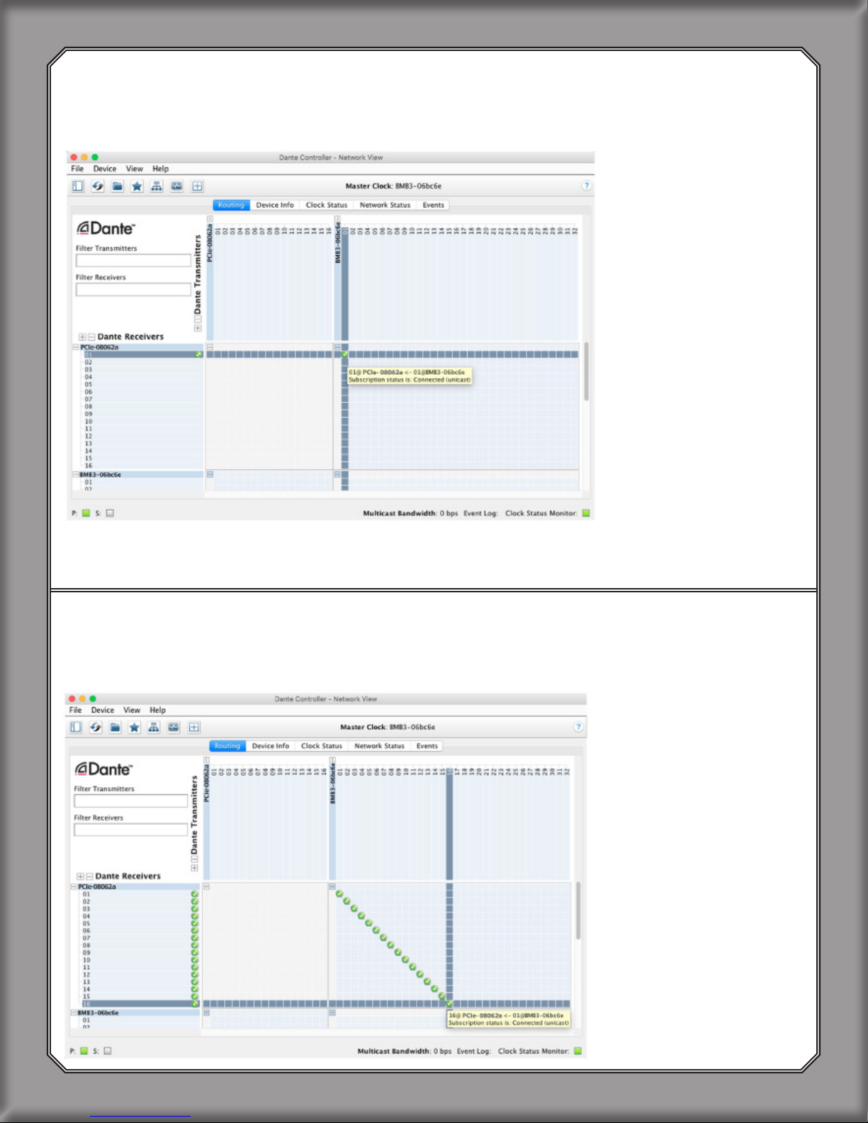
2.2 Download And Install Dante Controller
To download controller: https://www.audinate.com/products/software/dante-controller
2.3 Disconnect All Other Devices From Gigabit Switch
For best results, start by removing all other connections to the switch. Dante should be on its
own network. Use dierent network ports on your computer for other networks (such as internet).
2.4 Connect BMB3 Ethernet Port 1 to Gigabit Ethernet Switch
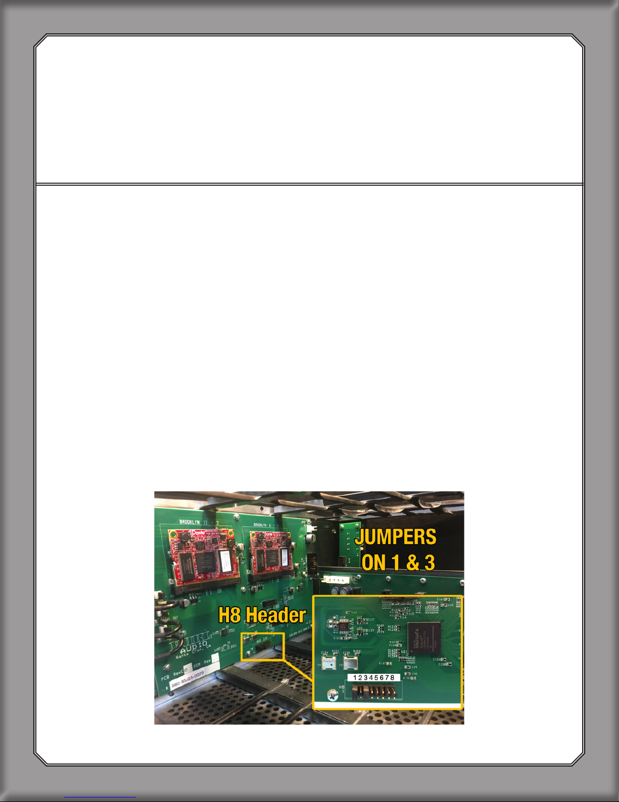
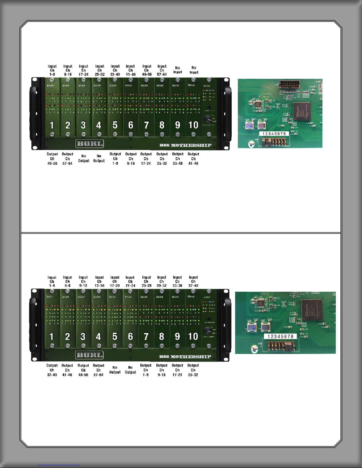
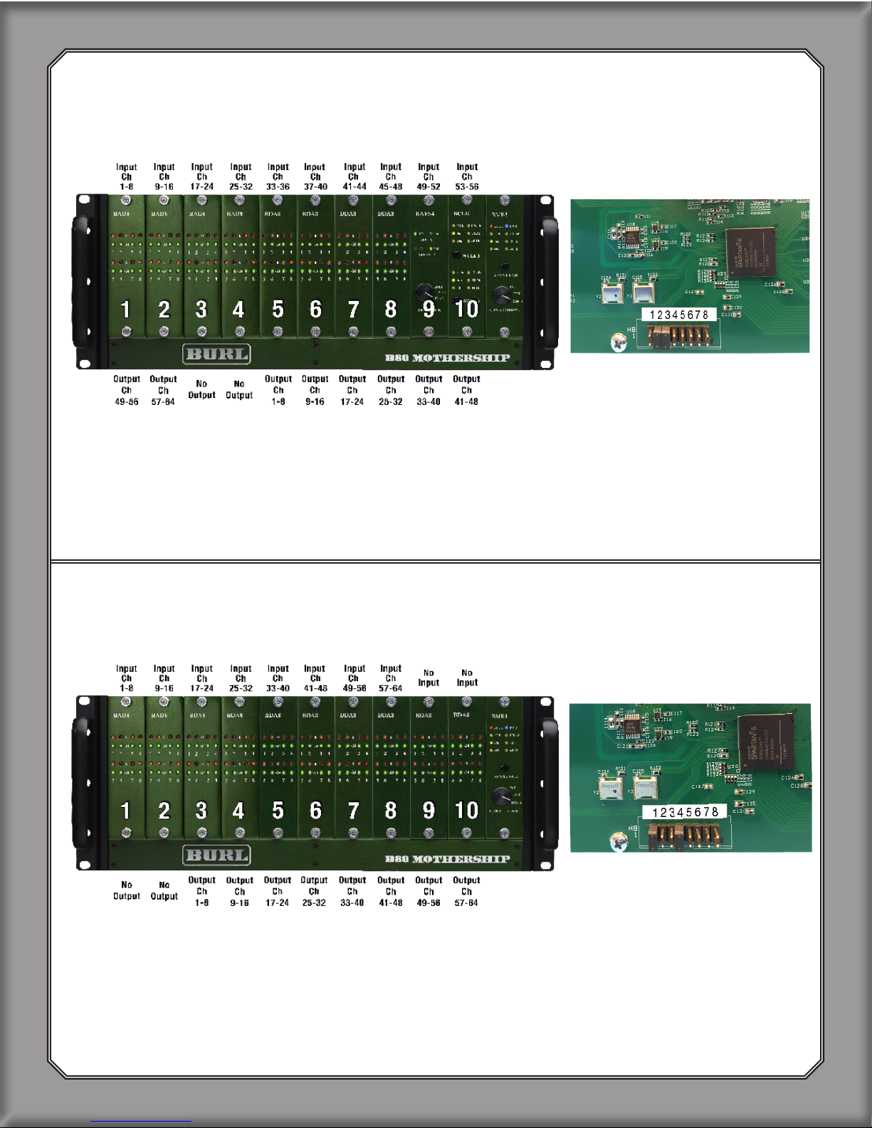
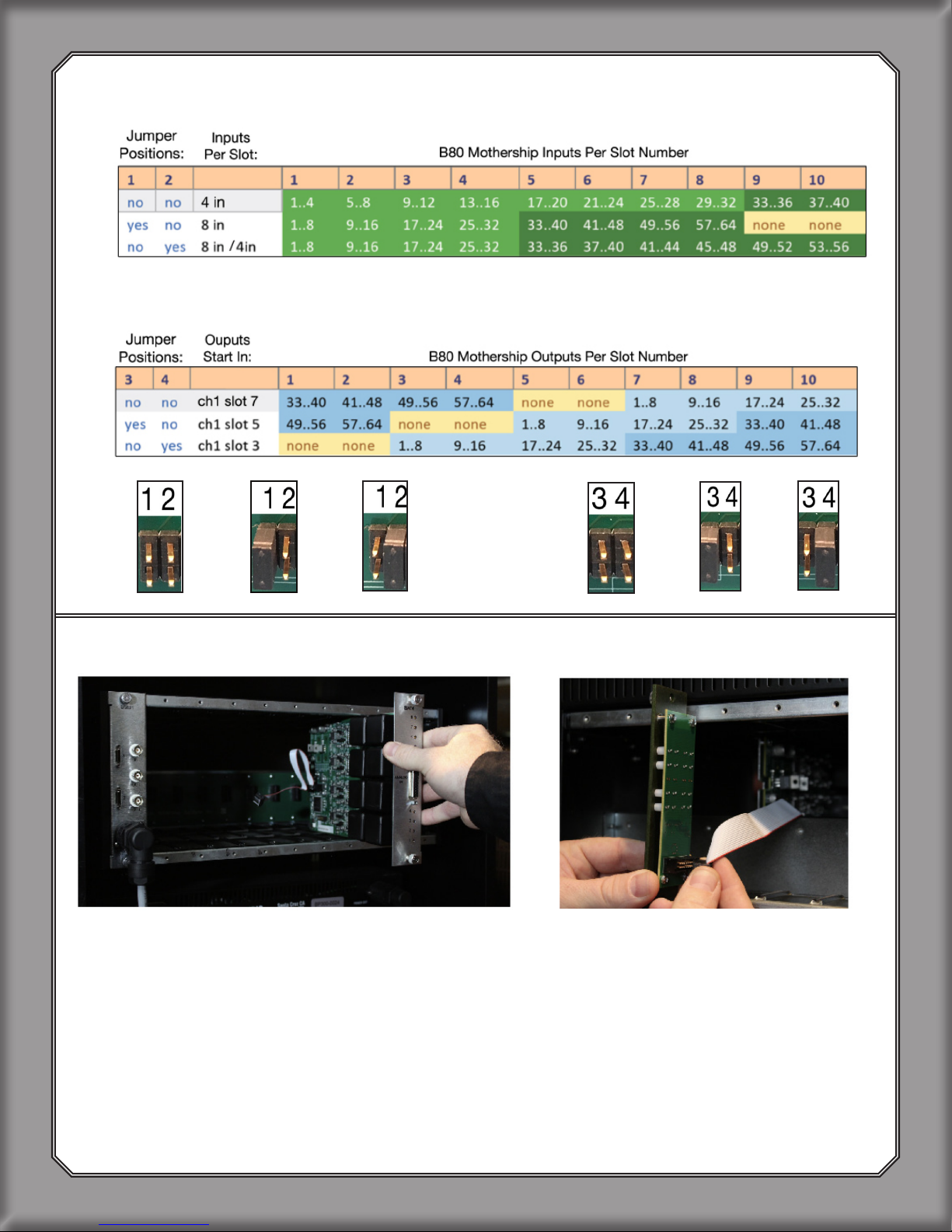
Each BMB3 port requires its own BKII-B80. An additional BKII Dante Card may be purchased
and installed into BMB3 Motherboard to maximize channel count.
6
SECTION 2

Image 9: BMB3 Front panel. Set Clock Control to INT, EXT, or DANTE
2.5 Set BMB3 Front Panel to INT, EXT, or DANTE
• When using the B80 on internal clock, set to INT.
• If using external word clock, set to EXT.
• When clocking o Dante network, set to DANTE.
For a complete guide to Dante Clocking, see page 12.
2.6 Connect The Computer’s Native Ethernet Port To Gigabit
Ethernet Switch
Even when using a Dante PCIe Card, Dante Controller requires a native Ethernet port and will
not work via the PCIe Card.
2.7 If Using A PCIe Card, Connect Primary Port Of PCIe Card
To Gigabit Ethernet Switch
When using a Dante PCIe Card, audio is transmitted via the PCIe card.
2.8 For INT, Set BMB3 To Desired Sample Rate
Push the “Sample Rate” button on BMB3 faceplate to toggle through sample rates. When set
to INT, BMB3 must always be manually set to the desired sample rate. When using EXT or
DANTE clock, the MOTHERSHIP will not need to be manually set via the front panel.
2.9 For Dante Virtual Soundcard (DVS), Open And Run DVS
2.10 Open “Dante Controller”
7
SECTION 2

2.12 Maximize The Routing View
Click on the “+” next to “Dante Receivers” and “Dante Transmitters (See Image 11).
Note: “Transmitter” refers to the signal from MOTHERSHIP input card sent to the BKII Dante
Card on the BMB3 Motherboard, and then to the PCIe Card (or CPU when using DVS).
“Receiver” refers to the PCIe Card sending signal to the BKII Card on the BMB3 Motherboard,
which then feeds the MOTHERSHIP output card.
Image 10:
Shows routing
BMB3 receiver
ch. 1-16 to
PCIe Card
channel 1-16.
2.11 Click On “Routing” Tab
(See Image 10)
Image 11:
Shows “Routing”
tab and “+” to
maximize routing view
to see all Receiver
and Transmitter
channels.
8
SECTION 2

2.13 Input Assignment
Route BMB3 Transmitter channel 1 to PCIe (or CPU if using DVS) Receiver card channel 1.
This routes B80 input ch.1 to PCIe (or DVS) card ch. 1 (See Image 12).
Continue with input assignments for your MOTHERSHIP conguration (See Image 16, pg 11).
2.14 Output Assignment
Route BMB3 Receiver channel 1 to PCIe (or CPU if using DVS) Transmitter channel 1.
This routes PCIe ch. 1 to B80 output ch. 1 (See Image 13).
Image 12:
Shows routing
BMB3 transmitter
channel 1 to PCIe
Card channel 1.
Image 13:
Shows routing
BMB3 transmitter
channel 1-16 to
PCIe Card
channel 1-16.
9
SECTION 2

(2.14 Output Assignment Continued)
Continue with output assignments for your MOTHERSHIP conguration.
See Image 14 for an example of routing B80 MOTHERSHIP outputs to the PCIe Card.
2.15 Click On “Device Info”
Then double click on BMB3 to open “Device View” window (See Image 15).
Image 14:
Shows routing
BMB3 receiver ch. 1
to PCIe Card
channel 1.
Image 15:
Device Info tab.
10
SECTION 2

2.16 Click On “Device Cong”
Select the sample rate and select preferred latency (See Image 16).
Note: Actual latency used between two endpoints is the larger of the two endpoint settings. If
using the Dante Virtual Soundcard (DVS), anything to or from DVS will have a 4ms latency in
and out. Using a PCIe Card is recommended to get down to 150μs.
2.17 Click On The Dropdown Menu
Select DEVICE CONFIG. for each Dante device including the PCIe Card.
Make sure the sample rate is matching on each device!
Note: Sample rate MUST be set for each unit, including the PCIe Card.
For more information on Dante, visit: https://www.audinate.com/solutions/dante-overview
Image 16:
Shows
device conguration
for BMB3.
11
SECTION 2

NOTE: “Preferred Master” refers to Dante Network, not BMB3 front panel!
3. DANTE CLOCKING
There are 3 ways to clock the B80 MOTHERSHIP:
1. BMB3 set to Internal. Brooklyn II (BKII) Card set to External.
2. BMB3 set to External Clock, BKII Card set to External.
3. BMB3 set to Dante, BKII Card set to Internal.
3.1 Clocking BMB3 To Internal Word Clock
1. Set BMB3 front panel to INT.
2. Open Dante Controller, select DEVICE INFO.
3. Double Click on device “BMB3-xxxxxx”.
4. Click on CLOCK STATUS (Image 17).
5. Set BMB3 to “Preferred Master”, and “Enable to sync to Internal”.
6. Make sure each device including host PCIe Card is set to correct
sample rate in Device Cong (see 2.16and2.17).
12
SECTION 3
SECTION 2
Image 17: BMB3 on Internal clock. BKII Dante Card is synced to BMB3 clock.

Image 18: BMB3 on External Clock. BKII Dante Card is also synced to External clock.
3.2 Clocking BMB3 To External Word Clock
1. Set BMB3 front panel to EXT.
2. Open Dante Controller, select DEVICE INFO.
3. Double Click on device “BMB3-xxxxxx”.
4. Click on CLOCK STATUS. (Image 18).
5. Set BMB3 to “Preferred Master”, and “Enable to sync to
External”.
6. Make sure each device including host PCIe Card is set to correct
sample rate in Device Cong (see 2.16and2.17).
13
SECTION 3

3.3 Clocking BMB3 To Dante
1. Set BMB3 front panel to DANTE.
2. Open Dante Controller, select DEVICE INFO.
3. Double Click on device “BMB3-xxxxxx”.
4. Click on CLOCK STATUS. (Image 19).
5. Set BMB3 to “Preferred Master”, and deselect “Enable to sync
to External”.
6. Make sure each device including host PCIe Card is set to correct
sample rate in Device Cong (see 2.18).
Image 19: BMB3 on Dante Clock. BKII Dante Card is also synced to Dante clock.
14
SECTION 3
Table of contents
Other BURL Recording Equipment manuals