Digiflex RF120 How to use

Installer
Reference Guide
RF120
SMART RF Base Station - RS485
Rev 1.20
®
RoHS

Page 2 P/N: RF120IRG Rev 1.20 E&OE Copyright © 2020
The SMART RF Base Station is an advanced 2-Way
433mhz transceiver that interfaces directly to compat-
ible control panels via an RS485 LAN connection. There
are two built in radio transmitters and receivers with
dual diversity internal antennas. Indicator lights display
the status at all times while front and rear tampers pro-
tect against unauthorised access.
Multiple RF120’s receivers can be installed on a single
LAN creating a network of access points where RF
devices can communicate across larger areas.
RF120 Base Station Receiver Compatibility
Panels Supported Version Receivers Supported
Vision-X 2.30 4
Solution 6000 2.30 4
Table 1: RF120 Compatibility
The 2-way communication is encrypted with rolling
code and anti substitution technology making the
RF120 an ideal choice for your wireless security system.
Receiver Addressing
Each receiver fitted to the system must be assigned a
unique address on the LAN. The RF120 includes a DIP
switch for quick address selection. The following table
shows the address setting for each keypad as well as the
number of keypad devices each panels can support.
Keypad Address Setting
Address S1 S2 S3 S4 S5
Base Station
1 OFF OFF OFF OFF
LAN Terminator
Switch
2 ON OFF OFF OFF
3 OFF ON OFF OFF
4 ON ON OFF OFF
Table 2: Receiver Address
i
Note
Only 1 receiver can be assigned to each address.
All receivers are supplied from the factory set to
address 1. You must power cycle the panel or
perform a LAN scan whenever you change the ad-
dress. Currently only 4 receivers are supported.
DIP Switch 5
LAN Termination if required can be enabled by
placing switch 5 in the ON position.
1
ON
2345
Figure 1: Receiver Address Switch
RF120 - SMART RF Base Station - RS485
Tamper Switch Operation
In your installation one or both of the case tamper
switches may not be needed. Setting switch 1 to the ON
position will disable the rear case tamper and switch 2 in
the ON position will disable the front cover tamper. From
the factory both tampers are enabled. The housing must
be correctly installed for the rear tamper to function cor-
rectly.
Switch 1 ON = Disable Rear Tamper
Switch 2 ON = Disable Front Tamper
1
ON
2
Figure 2: Tamper Switch Control
Box Contents
The RF120 box contains the following parts.
RF Base Station Receiver
Case (Front & Back) + LED Light Pipe + Cam Lock
Instruction Sheet
Bosch RF Device Compatibility
The RF120 Base Station is capable of supporting selected
Bosch RF peripherals like PIR’s, Reed Switches and Shock
Sensors etc. You must enable Bosch compatibility mode
in panel programming, MENU 6-2-0, Option 8 to enable
this feature.
For best performance, if you are not using Bosch RF
peripherals then you should leave this option disabled.
Mounting Considerations:
• The receiver should be mounted in a location that is
central relative to where the wireless devices will be
mounted.
• The receiver should be mounted on a vertical sur-
face with at least 30 cm clearance from other objects
as the antennas are internal.
• Avoid mounting the receiver in areas with significant
metal or electrical wiring.
• Avoid mounting the receiver in areas where it may
be exposed to moisture or high humidity.
• Reception distances are generally improved with
higher mounting locations and with no metal ob-
jects near the unit.
• If range is not achievable due to environmental or
specification limitations then add additional receiv-

P/N: RF120IRG Rev 1.20 Page 3
Copyright © 2020 E&OE
ers as required in strategic locations. Up to 4 receiv-
ers can be added.
Installation
The receiver should be installed onto a solid surface
using suitable mounting fixtures. Wiring should only be
performed while the control panel is powered down.
Step 1) Unlock and remove the front of the housing by
turning the cam lock anti-clockwise [Figure 4]
then release the spring clips and remove the
PCB, This will expose the mounting and tamper
screw holes.
Step 2) Mark out the location of the mounting holes
and the cable exit hole before drilling out all
points as necessary. Secure the case using fix-
tures appropriate for the wall construction type.
Make sure to fit the rear tamper screw when
mounting as shown.
Step 3) Feed any wires into the case via the knockouts
provided and then replace the PCB by inserting
from the terminal side first and then clipping
the other side in.
Step 4) Set the address for the module and connect
and necessary wiring. Unused wires should be
insulated to prevent short circuits.
Step 5) Once all connections are secure and the case is
mounted, secure the front case and lock in place
by turning the cam lock in a clockwise direction.
Mounting
Holes
Rear
Tamper
Cable
Knock Outs
Cable
Knock Outs
Figure 4: Cam Lock Shown
In The Unlock Position
Figure 3: Mounting Holes, Cable Knock
Out’s & Rear Tamper Locations
Figure 5: Rear Tamper Screw
CAUTION - Figure 3 below is a guide only and is not a 1: 1
mounting template for the RF120. Do not scale.
Page 4 P/N: RF120IRG Rev 1.20 E&OE Copyright © 2020
Multiple Receiver Wiring Connection
1
1
+
+
STATUS
TX
RX
TROUBLE
1
1
+
+
STATUS
TX
RX
TROUBLE
MODULE LAN
CONTROL PANEL
-A B
+
RED
BLACK
WHITE
BLUE
= LAN +
= LAN -
= LAN A
= LAN B
Control Panel
Wiring Legend
LAN +
SMART RF RECEIVER
LAN -
LAN A
LAN B
LAN +
SMART RF RECEIVER
LAN -
LAN A
LAN B
Receiver 1/4 Receiver 4/4
2 - 3
. . .
Figure 7: RF120 LAN Wiring
Receiver Operation
At start up the control panel will configure the receiver
with all the necessary information. The RF120 will
receive information and then send an acknowledge to
the RF device if it supports 2-way communication. For RF
devices that are only one way then no acknowledge is
sent.
Where two or more RF120 receivers are required to
achieve the desired coverage area there can be overlap-
ping areas where multiple receivers detect the same RF
device. The system will determine the receiver with the
strongest signal level and process it accordingly. The
seamless operation and wide coverage area using a LAN
connection allows easy deployment of receivers over the
full 1km control panel LAN length.
Receiver LED Indicators
The RF120 Base Station includes RED and GREEN LED
indicators which provide visual feedback during system
operation. See Table 3 for information on the indicator
colours and meanings.
Figure 6: RF120 LED Indicators
Module Indicator Lights
Position Colour Meaning Meaning
1 Red RF Transmit
Blinks each time a packet is sent to a device. In most
cases this will blink as an acknowledge is sent to a 2-way
device. Blinks each time a valid RF packet is received.
2 Green RF Receive Blinks each time a valid RF packet is received.
3 Red Trouble
Turns on when the receiver has detected a fault. This
could be a tamper or jamming levels exceeded. For a
self diagnostic issue the LED will slowly blink.
4 Green Status Blinks each time the system is polled by the control
panel.
Table 3: Receiver LED Indicator Descriptions

P/N: RF120IRG Rev 1.20 Page 5
Copyright © 2020 E&OE
Configuring RF110 Keyfob Button Functions
MENU 6-2-6 is used to customise the button functions
on the RF110 SMART RF 2-way keyfobs. Each of the 5
buttons can be programmed with two independent
functions if required with buttons 1 to 5 being a single
press function and buttons 6 to 10 being hold down
functions .
Up to 10 different functions in total can be programmed.
Figure 8: RF110 SMART RF Keyfob
i
Note
To trigger the hold down function you must press
and hold the keyfob button down for 2 seconds.
SMART Keyfob Function MENU 6-2-6
1) Press [MENU] + [6] + [2] + [6]. The keypad will
display the following options.
Button Function
Button Assignment
Exit
Press OK or SAVE
2) Use the up and down arrow keys to select the
Button Function option and press OK.
3) Use the up and down arrow keys to select the
Button to program (1- 10) and press OK.
Remember buttons 6 to 10 are hold down
functions.
4) Use the up and down arrow keys to select the
required function from the list of options and
press OK.
The following button functions are currently
available.
1 Disabled
2 Disarm
3Arm
4 Part 1
5 Part 2
6 Door
7 Output
8 Macros
5) Once the button functions have been configured
you need to set the function assignments for each
button. Select the Button Assignment option from
MENU 6-2-6 and press OK. Select the button to
configure and press OK.
6) The type of assignment available for each button is
determined by the button’s function.
The button functions Disarm, Arm, Part 1 and Part
2 must be assigned to one or more areas. The
button function Door must be assigned to a door,
button function Output to an output and button
function Macro to a macro.
7) Using macros, it is possible to configure a single
button to open multiple doors or to operate
multiple outputs.
i
Note
MENU 6-2-6 SMART RF Keyfob Function is only
effective when using the RF110 keyfobs. Other
keyfobs have fixed button functions that cannot be
configured separately.
Figure 9: SMART Keyfob Functions In RAS Software

Page 6 P/N: RF120IRG Rev 1.20 E&OE Copyright © 2020
Optional RF110FK Fascia Kit
An option fascia kit is available to allow customers to
personalise their keyfob or to match corporate colours
etc. Each kit is supplied with 7 different coloured facias
which have been pre installed onto top covers.
To change a fascia simply remove the screw from the
back of the keyfob, lift off the existing top cover and
fascia then replace with the new colour. Note keyfob
rubber keymats are not supplied with the kits.
Figure 10: RF110FK Fascia Kit

P/N: RF120IRG Rev 1.20 Page 7
Copyright © 2020 E&OE
RoHS
In the interest of ongoing product development this
document is subject to change without notice.
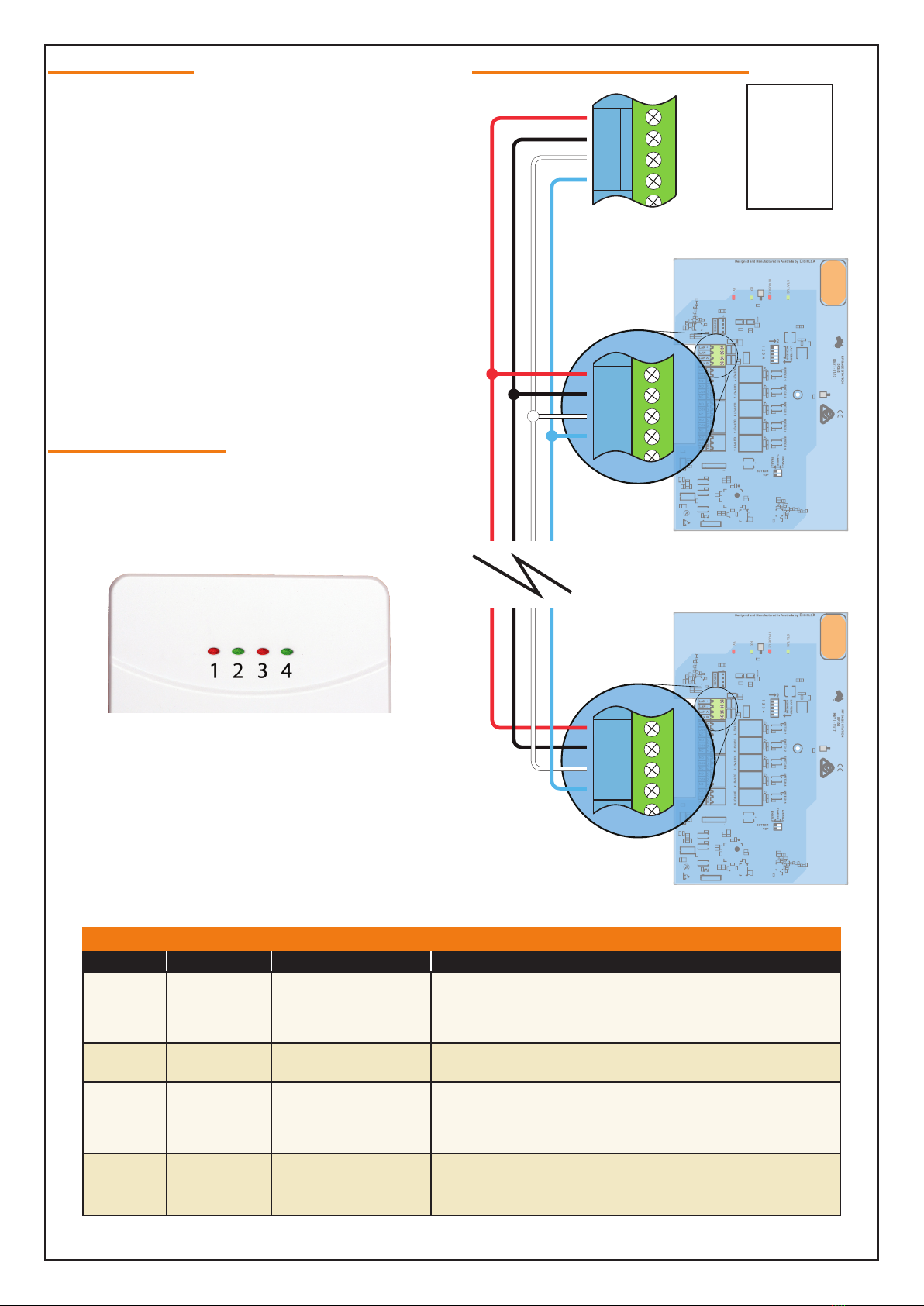
RF120 Connections
RF120 Specifications
Part Number: RF120 - SMART RF Base Station - RS485
Operating Voltage: 10V D.C. - 14V D.C. @ 70mA Max. 12V D.C .nominal
Module Connection: RS485 LAN
Frequency: 433.42 MHz
Dimensions: 140mm(W), 40mm(D), 270mm(H)
Environment: 0˚ to 49˚C Indoors
Fixing Method: Using mounting screws fix unit on a vertical surface in either landscape or portrait orientation.
Warranty: 3 years from date of manufacture (return to base).
DIGIFLEX
DF70
DIGIFLEX
DF70
DIGIFLEX
DF70
DIGIFLEX
DF70
1
1
+
+
STATUS
TX
RX
TROUBLE
Figure 11: RF120 / RF121 Connection Diagram
Relay output terminals
provided on RF121 Smart
Receiver Models.
Module Indicator Lights
(See table for indicator meanings).
Front and Rear \ Tamper
switch override. Use these
to disable the tamper switch
if required.
RD
BK
WT
BL
Relay test switches. These
can be used on RF121 to
check relay wiring operation
before closing the case. Relay
indicators are also provided.
Connection point for
CM799 Service Keypad.
Panel LAN
connection.
Refer to full wiring
instructions in
control Panel
installation manual
Front and rear
tamper switches.
Module address setting
switches.
Switch 5 can be used
the terminate the LAN if
necessary.

Copyright ©2002-2020 Digiflex Pty Ltd
P/N : RF120IRG Rev 1.20
DIGIFLEXPTY LTD
18 Brumby Street
Seven Hills NSW 2147
AUSTRALIA
Phone: (+612) 97417000
Email: [email protected]
www.digiflex.com.au
Our Vision Is Your Peace Of Mind
Made in
Australia
Table of contents
Other Digiflex Transceiver manuals


