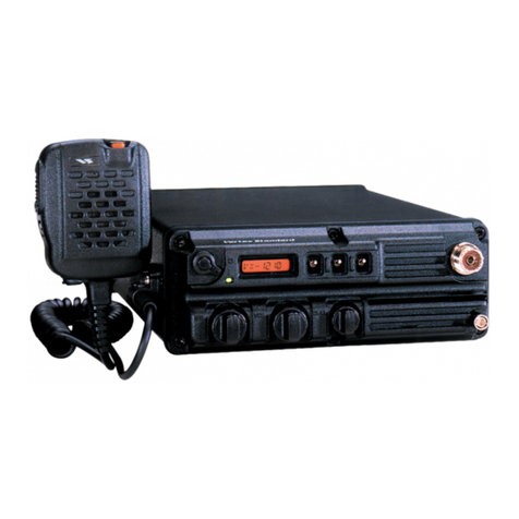
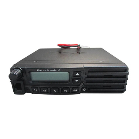
Vertex FTL-1011 User manual

"
FM Land MobileTransceivers
'OperatingManual
YAESU MUSEN CO.,
Ltd.
CP.0.
Box
1500,Tokyo, Japan
YAESU U.S.A.
17210EdwardsRd., Cerritos,CA 90701, U.S.A.
YAESU EUROPE
B.V.
Snipweg3,1118AA Schiphol,TheNetherlands

Congratulations!
You now have at your fingertipsa valuable communications
tool
-
aYaesu two-wayradio!Rugged, reliableand easytouse,
i
your Yaesu radio will keep you in constant touch with your
I
colleagues for years to come, with negligible maintenance
down time.
Please take a few minutes to read this manual carefully. The
information presented here will allow you to derive maximum
performancefromyour radio. After reading it, keep the manual
handy for quick reference, in case questions arise later on.
We're glad you joined the Yaesu team. Call on us any time,
because our business is communications. Let us help you get
your message across.
NOTICE
There are no user-servicable points inside this trans-
ceiver.All servicejobs mustbe referredto yourAuthorized
Service Center or Network Administrator.

FTH-1011, FTL-2011 VHF
and FTL-7011 UHF
FM Land MobileTransceivers
The 60-watt VHF Low-Band FTL-1011, 40-watt VHF High-
Band FTL-2011 and 25-wattUHFFTL-7011 are rugged, full-fea-
tured FM transceivers designed for flexible mobile and base
stationbusiness communications. Each model is available with
either a
-4
or-12suffix,with acapacityof either4or 12channels,
respectively
.
Reliability is assured by a highly integrated surface mount
circuitdesignandadie-castaluminumchassis.Importantchan-
nel frequency data is storedinEEPROM, and is easilyprogram-
mable by dealers using a personal computer and the Yaesu
FRB-2 Interface Box, T9101410 Cable and CE-5 or VPL-1 Soft-
ware.
Special features include a built-in CTCSS (ContinuousTone
Coded Squelch System) and in the 12-channel versions, two
sets of scanning channels, one set preselectable by the dealer
and another operator selectable.The operator can select which
set to scan, and also two priority channels.Dealerscanprogram
Busy Channel Lockout, transmitter time out timers and scan
stop activities for talkback on the paused channel, priority
channel or the home channel (onwhich scanningwas initiated).
Scanningis not provided in the 4-channel versions.
Each transceiver issupplied with a mobilebracket andhand
microphone. Options include the FP-711 Power Supply for op-
erationfrom the AC mains, the FDS-1 DigitallyCoded Squelch
Unit and F2D-4 2-Tone Decoder programmable by your dealer.
Please take a few minutes to read this manual carefully. The
information presented willhelpyou derivemaximumperform-
ancefrom the equipment. After reading, keep it handy near the
radio for quick reference.

Controls
&
Connectors
Front
Panel
--
@
0
C
--
--
-
-4
Suffix
(Cchannel)Models
0
00 0
-12
Suffix
(12-channel)Models
@
Microphone Jack
Connect the microphone plug to this jack.
@
MON
Button
&
Indicator
This button selects the squelch (receiver mute) mode. When the
indicator is off, tone (orcoded)squelchis active.When the indica-
tor glows steadily (after pressing this button momentarily or re-
moving the microphone from its hanger), only noise squelch is
active, and any signal will be heard. Holding this button for two
secondsdisablesall squelch,and the yellow indicatorblinks. If the
indicator is blinking, press this button once toreturn the previous
squelchmode, and again to selectthe other mode.
@
A
(Accessory) Button
&
Indicator
In the FTL-loll/-1014, this button activates the noise blanker. In
the other models this button (and the green indicator above it) is
provided for special applications, such as high/low power selec-
tion, talk-around and call alert functions, as determined by your
networkrequirements andprogrammedby your Yaesu dealer.The

Vertex
FTL-1011, FTL-2011
&
FTL-7011
OperatingManual
green indicator lights when the function is active. Your network
administrator can advise you of the functionof this button (if any).
Otherwise, it may be disabled.
@
Volume and Power
OnfOff
Knob
Thisknobadjuststhereceiver volume, and turnsthetransceiveroff
when turned all the way to the left intothe click-stop.
@
BUSYITX
Indicator Lamp
This lamp glows green when the channel is busy, and red while
transmitting. Do not transmit when this indicator is green.
Thefollowing item is unique to4-channel versions:
@
CHANNEL
Numbered Indicators
&
Button
Pressthebutton to selectthe operatingchannel,indicatedby which
of the numbered orange LED indicators is lit.
Theremaining items are unique to12-channel versions:
@
ChannelSelectorKnob
Turntoselect the operating channel,as shown on the display.
@
Numeric ChannelDisplay
Showsthe selected channel number and priority/scan status. The
P
and
E
dots at the top of the display light
if
a channel is enabled
for user-selectable priority or scanning,respectively.
@
PRI
(Priority)Button
Thisbutton is used toselect a channel for priority monitoring,and
together with the
SCAN
button for selecting scanning modes, as
described in the next chapter,
How to Use the Transceiver.
@
SCAN
Button
This button is used to activate scanning, to select and deselect
channels for scanning, and together with the
PRI
button to select
scanning modes, as described in the next section.
Page
3

Vertex
FTL-1011, FTL-2011
6
FTL-7011
Opevati/?g
Mnnual
REAR
(Heatsink)
@
13.6VDCCable Pigtail wlconnector
The
supplied
DC
power cable must be connected to .this 2-pin
connector. Use only the supplied fused cable, extended if neces-
sary, for power connection.
@
Antenna Socket
The50-ohmcoaxialfeedline to the antenna mustbe connected here
using a type-M (PL-259)plug.
@
EXT
SP
(ExternalSpeaker)
Externalloudspeakers may be connected to this 2-contact, 3.5-mm
mini-phone jack.

HowTo Use TheTransceiver
Important!
-
Before turning on theradio the first time, confirmthat
the power connectionshave been made correctlyand that a proper
antenna is connected to the antenna jack.
If
the transceiver is not
installed, see
Installation
near theback of this manual.
Turn the Volume/Power knob clockwise to turn on the radio.
LEDs will light, indicating the channel and status of the radio (as
set when last used).
In4-channelversions press the
CHANNEL
button tochangechan-
nels. In 12-channel versions, the display should show either a
channel number or scan mode indicator (Sc,
Ur,
SP or UP). If
E2
is
displayed instead, the transceiver has not yet been programmed
with channel frequencies: switch off the power and contact your
network administrator or Yaesu dealer.
If
a scan mode indicator is
displayed, you can press the
SCAN
button to display a channel
number, and turn the selectorto change channels.
or
2:
not i
loved fr
r
any sig
may use
Coded
Squelch
-
the
MON
Button
Your tran the built-in CTCSS (Continuous Tone
Coded SquelchSystem),or optional DCS (DigitallyCoded Squelch)
Tone Sequential Codes, to keep the recei~ for all
s
ntended for you.
he transceiver may be programmed so tnat wnen the mlcro-
xe is ren om its hanger, coded squelch is defeated, and
can heal ;nal on the channel (the yellow
MON
indicator
be lit). kou can get the same result without lifting the micro-
xe, by pressing the
MON
button momentarily.To avoid listening
lnecessary chatter,keep the microphone in its hanger, and press
tne
MON
button when necessary to turn the yellow indicator off
unless you want to listen to other calls.
Holding the
MON
button for two seconds defeats not only coded
squelch, but also the noise squelch, so background noise can be
heard (the
MON
indicator blinks). This is useful for setting the vol-
ume when no signals are present. Press
MON
momentarily to return
the
J
to its prc ate (off, or steadily on).
"
~dicator
,
,
7er quiet ignals
Vertex FTL-1011, FTL-2011
t3
FTL-7011 OperatingManual
Settingthe Volume
If no signalsareheard and the
BUSYrrX
indicator isnot glowing
green (soyou canadjustthevolume on a signal),press andhold the
MON
button for two seconds until a beep is heard and the yellow
indicator above the button blinks. Then adjust the volume control
fora comfortablelevel on a signal or background noise,Press
MON
again momentarily so the yellow indicator stops blinking. See the
box on the previous page for more information on controlling the
squelch system.
Transmitting
To transmit, wait until the
BUSYrrX
indicator is off (thechannel
isnot inuse), and press the PTT (Push-To-Talk)switch on the side
of the microphone (the
BUSYITX
lamp glows red).While holding
the
PTT
switch, speak acrossthe face of the microphone in a clear,
normal voice, and then release the PTT switch to receive.The box
below describes some other features that may be programmed to
affect your transmissions.
Remaining instructions apply to12-channel versions only.
Scanning
Four scanning modes are available when the
SCAN
button has
been pressed. Once'a scan mode is selected, it remains selected
If th
out,
yoL
ting, a
'
beep sc
.*T
.
a momc
)ur trans
itter will
e selecte
1
must lii
beep sol
xtt, and
pecial
.
not acti
.
r
~dchann
mit the
1t
lnds ten
the timt
.
.
then prc
Trans;
s progra
vate wh
,-
I.
.elhas
bc
qthof
second:
?-outpel
.
.
!ssit aga
ock-out,
ssed
ud
.
.a
CI
Functions
If
yc
mmed for
busy
channel
1
transm: en the
PTT
switch is pre:
the
BUSYlTX
lampis orr (toprevent interferenceto other stations).
een programmed for
atitolnafic
time-
your transmissions.Whiletransmit-
;
before time-out, and then another
riod expires:the
BUSYRX
irdicator
will turn orr ana transmission will cease. Release the
MT,
listen for
in to res
-
ume trainsmittin,

Vertex
FTL-1011, FTL-2011
&
FTL-7011
Operating Manual
when thetransceiver isturned off, orwhen scanningisdisabled (by
pressing the
SCAN
button again, so that a channel number is dis-
played).The
SCAN
modes and their corresponding displays are as
follows:
Display Scanning Function
Sc
Scan all channels
U
r
Scan only user-selectedchannels
SP
Monitor one channel and pre-programmedpriority(ies)
UP
Scan user-selected channels with user priority(ies)
The user-selected channels for the
Ur
and
UP
modes are those
you can set yourself, as described
in
the box on the next page. The
priority channels are those onwhich signals will take priority over
signals received on other channels: that is, if a signal appears on a
priority channel while another appears on a non-priority channel,
the priority signal will beheard, and not the other.Up to two of the
installed channels maybe designated by your network administra-
torordealeraspre-programmed priority channels for the
SP
mode
(theradio does not indicate which they are),and you can program
any two channels as user priorities for the
UP
mode. The non-pri-
ority channel in the
SP
mode is the onelast displayed.
While a scan mode is displayed, you can select another by
pressing the
PRI
button repeatedly (thedisplay will cycle through
the above). Make sure the microphone is in its hanger if you want
scan
catoi
chan
or wher
:he displ
.,&*A
c,
1.
-.
1
scannir
lay
may
.A
;--l..A
p
(p
1)
t?
E
(ScanEnable) Indic
Jhen achannel number is displayed,either during manual
ning)operation, lg is pau
i
indi-
rs at
the
top of
t
be lit.
TT
at the
~nelhasbeen seleLLCU
LV
VC
IILLILLJedin uscl
scalLlL11L6
llrvc~es
(Ur
and
UP).
If the
P
indicator is blinking nnel is the 1st(highest
priority) channel for the
UP
mode.
If
tl )tblinkingbutsteadily
on, the channel is the 2nd priority
C~I~I~II~I.
30th priority channels
serve asordinary user-selected scan channels in the
Ur
mode.
,
the cha
le
P
is nc
..
1
1
P
and
E
licate th
(non-

Vertex
FTL-1011, FTL-2011
&
FTL-7011
Operating Manual
to hear only calls intended for you. While scanning, if a signal is
received which includes the correct code to open your squelch,the
channel number on which the signal appears will be displayed as
you hear their call, and the display will then alternatebetween the
scan mode indicator and the channel number. Scanning will re-
sume automatically either after a preset interval of a few seconds,
or after the station stops transmitting (depending on how your set
was programmed).
Yo
chanr
.
.
Tu
back
c
Th
when
.
Note:
chann
--~
)
determ
ioring, rc
p left of
clearing
els (both
C.
amming
rogram
i
!
priority
...
~diooff,
lisplay
T
priority
L
P
and
E
1
.r
have thc
.
.
3
set of
.
monitoi
.
-
then holm
will indic
--
User-
Progr
lble Channel Select
u can pi channels to be scanned, and up to
2
~elstobe red. Selections arcretained in memory
until changed or deleted.
1
o create or modify the selections:
rnthe ra d the
SCAN
button while switching it
XI.
The
(
:ate a channel number.
e
E
(scan enable)indicator at the top center of the displayislit
thedisplayed channel is tobe included inUser-selected chan-
nel scanning.Press the
PRI
button, if necessary, to set the
E
indicntnr
asdesired for thischannel. Thenturnthe channelselect,
the selection/deselection process oneach channel.
Tc ine which channels are currently selected for priority
monil ~tatethe channel selector and watch the
P
indicator at
the to the display. At the 1stpriority channel the
P
indicator
will blink, atthe 2ndtheindicatorwill staylit.To changethepriority
channels, first cancel
both
by selecting
either
and pressing the
PRI
button. Then select the 1stnew channel, andhold the
PRI
button for
two seconds, until a beep sounds and the
P
ii blinks.
select the2nd new channel, and again hold the ton, this
until the
P
indicatorjust lights.
selectionsalso clears scan
indicators off), so be sui
scannlng arrerwaras,
ir
desired.
When you
I
asdesix
and prioritv monitorinn, press thc
SCAN
button to exit the
,,,,
Progr
,
mode a ma1 ope]
-
L
nd retur
bls set u~
.
-
n to nor:
ndicator
PRI
but
1
selectio
re to rest
.ed for
L
ration.
or andre
n
of the
r
?lectther
rser scan
.
-
Next
time
same
n for
ning
7
cnr

Installation
Normally, your Yaesu Dealer will provide completeinstallation
of all stations in your system. However, basicinstallation informa-
tion is provided here for your reference.
For mobile service, your transceiver should be installed so the
controls,indicatorsand microphoneareeasilyaccessiblefor opera-
tion and viewing, without interfering with road vision, and sothat
the loudspeakermaybe easilyheard.Theradio may be installed in
any position without loss of performance. Typical locations are
beneath the dashboard or atop the transmission tunnel in small
vehicles, oroverhead in a truck cabin.
The
MMB-48
universal mounting bracket and mounting hard-
ware aresupplied with the transceiver.
Mobile
Mounting
Procedure
0
Usingthemounting bracket asa template, mark thelocationsof
the mounting holes in the desired position.Use a
3/16"
diame-
ter bit to drill the holes after making certain that there will be
enough space for the transceiver, connecting cables and con-
trols. Secure the bracket with the screws, washers and nuts
supplied,asshown in the drawingon the next page.
0
Position the transceiver in the bracket so that the holes in the
sidepanelsarealigned withthoseinthesidesof thebracket, and
bolt the transceiver into place with the supplied short screws
and flatwashers.
0
Themicrophonehanger must be installed soas to make electri-
cal contact with the car body. Otherwise the hanger may be
installed wherever convenient.

Vertex
FTL-1011, FTL-2011
&
FTL-7011
Operating Manual
A
A
Base StationInstallation
TheFP-711AC Power Supplycanoperate the transceiverfroma
variety of AC voltages. Connect the fused DC Cablesupplied with
the transceiver to the terminals on the rear of the FP-711.
NOTE:
In all installations,means must be provided to ground the
metal mounting loop on the microphone in order for the squelch
and scanning/monitoring systems to function. In base installa-
tions, a grounding hook must be provided in which to rest the
microphone when not transmitting.
Power Connections
For mobile installations,connectthe power cable directlyto the
vehiclebattery.Thisallows the radio to operatewithout turning on
the ignition, and may alsoreduce noisein the receiver. Connection
Perma
revers
b
ution!
power
r
is
--
---
reversed pow
Image
v
r
warra
vill resu
nty doc
er supp
.Itif the
.^
-,.A
-
ections.
page
10

Vertex
FTL-1011, FTL-2011
&
FTL-7011
Operating Manual
to the cigarettelighter orother existing circuitsmay result in over-
load, or degrade transceiver performance.
Always use the supplied DC power cable, which includes fuses
to protect you, the vehicle and the equipment. If the cable is too
short, use
#12
AWG stranded,insulated copper wire to lengthen it.
Use the shortest length possible, connected to the end of the DC
cable that doesnot have connectorsinstalled.
Refer to the diagramsbelow for power cable connection details.
0
Before connecting the supplied DC cable to the transceiver,
connect the RED lead of the DC cable to the POSITIVE
(+)
battery (orpower supply)terminal, and theBLACK lead to the
NEGATIVE
(-)
terminal.
0
ConnecttheDC powercableto theconnectoronthecablepigtail
attheback of the transceiver.
0
Connect the coaxialplug on the antenna cable (notsupplied)to
the coaxialantenna jack onthe transceiver.Antenna impedance
must be
50
ohms at the operating frequency.
0
Connect the microphoneplug to thejack onthe transceiver.
0
If anoptional externalspeaker is to be installed,insert the plug
from the speaker into the
EXT
SP
jack onthe rear (disablingthe
internal speaker).

Maintenance And Service
Keep the outside of the transceiver cleanby wiping with a soft
cloth as necessary. Avoid rain or immersion in water, and protect
theradio fromdustas much aspossible.Do not openthecase.If the
radio fails to operate, check the cable connections, and inspect the
fusesin the
DC
cable.
Regular Maintenance Plan
Your Yaesu dealer will advise you of the maintenance plan that
best suits your needs. We recommend that the transceiver be re-
turned to your Yaesu dealer at least once every two years, for
testingof receivingsensitivityand transmitter power output.If the
need for servicing does arise, phone your Yaesu dealer for an
appointment.
He
will be pleased to answer any service-related
questions,and his qualifiedservicetechnicianswill make surethat
your radio is back in serviceasquicklyas possible.
Fuse Replacement
If a fuse is blown try to determine if the failure was caused by
something outside of the radio (like
a
short circuit due to a worn
cable). Contact your dealer at once if you do not find the cause.
Replace fuses only with the sametype installed.
Service Information
If the transceiver fails to operate, check the fuses in the power
cable. If either is blown, attempt to locate and correct the cause of
the problem before replacing the fuse(s).These radios have no
user-serviceableparts inside.
Caution
when replacing fuses,
2
correc ow>
and rating (IOA, or
15A
f
-1011). ting
from use of an improper fuse 1s not covered
by
warranty.
use thc
'or
FTL
:t type
Damag
.
.
(fast-bl
;eresul
page
12

Specifications
General
Frequency Range
(version) FTL-1011: 37
-
48 MHz
FTL-2011: 134
-
1601148
-
174MHz (vers. A/C, resp.)
FTL-7011: 400
-
440 MHz (A), 420
-
460 MHz (B),
450
-
490 MHz (D)or 480
-
512MHz (F)
Nr.
of Channels
&
Spacing
4 (-4 models), 12(-12 models, 24 chs optional)
25-kHz spacing (12.5-kHz optional)
Mode of Emission
16KOF3E(direct frequency modulation)
Antenna Requirement
5042, unbalanced (SO-239 socket)
Voltage Requirement
10.8to 15.6
V
DC,
negative ground
Current Consumption
(approx.) 300 mA Stby, 700 mA Rx, 7.0 A Tx (FTL-1011:9A)
Operating TemperatureRange
-30 to +60 OC (-22 to +I40OF)
Size
(WHD, approx.) 160
x
50
x
180mm (6-1/4
x
2
x
7-h")
Weight
(approx.) 1.5kg (3.3 lbs.)
Receiver
Receiver CircuitType
Intermediate Frequencies
Sensitivity
Hum
&
Noise Ratio
Adjacent Channel Selectivity
Intermodulation Distortion
Spurious Rejection
Audio Output Power
Double Conversion Superheterodyne
16.9MHz (FTL-101
I),
21.4 MHz (FTL-2011)or
47.9 MHz (FTL-701
l), and 455 kHz (all models)
0.2510.3 pV for 12dB SINAD,
0.3510.45 pV for 20 dB
QN
(VHFIUHF,resp.)
Better than 45 dB
>80/75 or 70dB (FTL-loll/-2011
and
-7011,resp.)
Better than 70dB (3-signal)
Better than 80dB (VHF), or 70 dB (FTL-7011)
5
watts into 4 ohms with <lo% THD
Transmitter
Power Output
FTL-1011: 60 watts (fixed)
FTL-2011: 4015 watts (highllow,programmable)
FTL-7011: 2512 watts (highllow,programmable)
Modulation TypeBeviation
Frequency Modulation,
f
5 kHz
(+
2.5 kHz opt'l)
Hum
&
Noise Ratio
Better than 45 dB
Modulation Distortion
Less than 5%
Spurious Emissions
Better than 70dB (below carrier)
Microphone Impedance
600
SZ
Specifications subject to change without notice or obligation.
page
13

Supplied Accessories
MH-5j8Microphone (optionalin North America)
Fused DC Cable: T9017910Aw/two
10-A
fuses
(15-Ain FTL-1011)
MMB-48 MobileMounting Bracket
OptionalAccessories
FDS-1 DigitallyCoded SquelchUnit
F2D-4 Sequential 2-Tone Decoder
FRB-2 Programming InterfaceBox
CE-5 Programming Software(forIBM PC/compatibles only)
VPL-1 ProgrammingSoftware(for
IBM
PC/compatibles only)
T910141
0
Programming Connection Cable
T9101411Radio-to-Radio Cloning Connection Cable
F'P-711 AC (BaseStation)Power Supply
page
14

YAE
SU
Perfdrmance without compromise
E02561101(405m-ZT)
Printed in Japan.
This manual suits for next models
2
Table of contents
Other Vertex Transceiver manuals

Vertex
Vertex VX-410 series User manual

Vertex
Vertex VX-1700 User manual

Vertex
Vertex HX370S User manual

Vertex
Vertex VX-920 Series User manual

Vertex
Vertex FT-817 Manual

Vertex
Vertex EVX-531 User manual

Vertex
Vertex VX-230 Series User manual

Vertex
Vertex VX-7R Manual

Vertex
Vertex VX-6R Manual

Vertex
Vertex VX-1210 User manual

Vertex
Vertex VX-5R Manual

Vertex
Vertex FT-817 Manual

Vertex
Vertex VX-4500 Series User manual

Vertex
Vertex VX-2100 series User manual

Vertex
Vertex VX-160EU User manual

Vertex
Vertex VX-6E Manual

Vertex
Vertex VX-8GR Manual

Vertex
Vertex FTL-1014 User manual

Vertex
Vertex VX-3R/E Manual

Vertex
Vertex VX-7200 User manual