Digifly AIR Pro BT User manual

AIR Pro BT
Firmware 142 IT
Rev. 53 a UK
User Manual

Page 2
CONGRATULATIONS
Thank you for choosing Digifly!
You have purchased a high technology instrument designed expressly for free flight. The multiple functions
and flight data it provides, effectively make it an on board computer. Learning to use this instrument will
make your flying easier in terms of performance and safety. It will enable you to improve your flying
technique and make piloting decisions more quickly thanks to the comprehensive flight information that
is provided. Another benefit is the ability to download and analyze your flight data afterwards.
Our designing effort foresees also to the future software developments, so the software at the heart of this
instrument can be updated at any time via the Internet using the Digifly PC cable.
DIGIFLY INTERNATIONAL GUARANTEE
Dear Customer,
Thank you for purchasing this Digifly product which has been designed and manufactured to the highest
quality standards. Digifly warrants this product to be free from defects in materials and workmanship for
3 years from the date of purchase.
The Digifly guarantee applies provided the product is handled properly for its intended use, in accordance
with its operating instructions and upon presentation of the original invoice or cash receipt, indicating the
date of purchase, the dealer’s name, the model and the serial number of the instrument.
The customer is however, responsible for any transportation costs. The unit must be securely packaged for
return.
The Digifly guarantee may not apply if:
- The documents have been altered in any way or made illegible.
- Repairs or product modifications and alterations have been executed by unauthorized person or service.
- Damage is caused by accidents including but not limited to lightning, water or fire, misuse or neglect, or
every malfunction not related to manufacturing defects of your instruments.
If your Digifly product is not working correctly or is defective, please contact your Digifly dealer. In order to
avoid unnecessary inconvenience.
Digifly Europe s.r.l.
Bologna
Italy
www.digifly.com

Page 3
1INDEX
1INDEX ..................................................................................................................................................................3
2GETTING STARTED ............................................................................................................................................6
2.1 CONNECTIONS ...................................................................................................................................................................6
2.2 BATTERY .............................................................................................................................................................................6
2.2.1 BATTERY RECHARGE...............................................................................................................................................6
2.2.2 EXTERNAL POWER SUPPLY....................................................................................................................................6
2.3 KEYBOARD -NORMAL OR LONG KEY PRESS ...............................................................................................................6
2.4 TURNING ON &OFF ...........................................................................................................................................................7
2.5 DISPLAY CONTRAST ADJUSTMENT.................................................................................................................................7
2.6 MENU...................................................................................................................................................................................7
2.6.1 DISPLAY’S FIELS EDITING .......................................................................................................................................7
2.6.2 ALPHANUMERICAL FIELDS EDITING .....................................................................................................................8
2.7 MULTI LANGUAGE HELP ...................................................................................................................................................8
2.8 RESTORE FACTORY SETTINGS ........................................................................................................................................8
2.9 RESET..................................................................................................................................................................................8
3QUICK REFERENCE GUIDE.................................................................................................................................9
3.1 SYMBOLS MENU................................................................................................................................................................9
3.2 PLOTTER SCREEN........................................................................................................................................................... 10
3.3 COMPASS SCREEN......................................................................................................................................................... 11
4DISPLAY.......................................................................................................................................................... 12
4.1 MAIN SCREENS.............................................................................................................................................................. 12
4.2 PLOTTER AND COMPASS SCREENS –INSTRUMENTS FIELDS ............................................................................ 13
4.2.1 VARIOMETER ....................................................................................................................................................... 13
4.2.2 ANEMOMETER ..................................................................................................................................................... 13
4.2.3 GRAPHIC ALTIMETER ........................................................................................................................................ 13
4.2.4 COMPASS SCREEN ESSENTIAL INSTRUMENTS........................................................................................... 13
4.2.5 PLOTTER PAGE ESSENTIAL INSTRUMENTS..................................................................................................... 13
4.2.6 NAVIGATION PLOTTER SCREEN ...................................................................................................................... 14
4.2.7 HSI NAVIGATION PLOTTER PAGE................................................................................................................... 14
4.2.8 BEARING COMPASS .......................................................................................................................................... 14
COMPASS SCREEN MAIN FIELDS .......................................................................................................................................... 14
4.2.9 COMPASS SCREEN, NAVIGATION TO THE START LINE................................................................................. 14
5BASIC FUNCTIONS........................................................................................................................................... 15
5.1 ALTIMETERS.................................................................................................................................................................... 15
5.1.1 ALTIMETERS SETTINGS........................................................................................................................................ 15
5.2 VARIOMETERS ................................................................................................................................................................ 15
5.2.1 SUPERFAST INTELLIVARIO................................................................................................................................... 15
5.2.2 VARIO SENSIBILITY ............................................................................................................................................... 15
5.2.3 VARIO REACTIVITY ................................................................................................................................................ 16
5.2.4 ANALOGICAL VARIO.............................................................................................................................................. 16
5.2.5 INTEGRATED AVERAGE VARIO ............................................................................................................................ 16
5.2.6 ACOUSTIC VARIO................................................................................................................................................... 16
5.2.7 ACOUSTIC VARIO PRE-THERMAL ADVIDSE ...................................................................................................... 17
5.2.8 VARIO SIMULATOR................................................................................................................................................ 17
5.3 AIR SPEED (ANEMOMETER WITH OPTIONAL PITOT TUBE).................................................................................. 17
5.4 ANEMOMETER SETTING (WITH OPTIONAL PITOT TUBE)....................................................................................... 17
5.5 TIME &CHRONOGRAPH................................................................................................................................................ 17
5.6 DISTANCES...................................................................................................................................................................... 18

Page 4
5.7 AIR EFFICIENCY (GLIDE RATIO) .................................................................................................................................... 18
5.8 TRACKING &BEARING .................................................................................................................................................. 18
5.9 BAROMETER ................................................................................................................................................................... 18
5.10 TIME/CHRONOGRAPH SETUP ..................................................................................................................................... 18
5.11 PILOT’S NAME &GLIDER’S DATA................................................................................................................................. 19
6ADVANCED FUNCTIONS.................................................................................................................................. 19
6.1 TOTAL ENERGY COMPENSATION ................................................................................................................................. 19
6.2 POLAR (WITH OPTIONAL PITOT TUBE)......................................................................................................................... 19
6.3 SPEED TO FLY (WITH OPTIONAL PITOT TUBE) ........................................................................................................... 20
6.4 MCCREADY (WITH OPTIONAL PITOT TUBE) .............................................................................................................. 21
6.5 EQUIVALENT CCREADY (WITH OPTIONAL PITOT TUBE) ............................................................................................. 21
6.6 NETTO VARIO (WITH OPTIONAL PITOT TUBE) ............................................................................................................ 21
7GPS FUNCTIONS.............................................................................................................................................. 22
7.1 INTEGRATED 99 CHANNELS GPS RECEIVER ............................................................................................................ 22
7.2 GPS STATUS INFORMATION......................................................................................................................................... 22
7.3 GPS INFORMATION DISPLAY........................................................................................................................................ 22
7.4 LATITUDE &LONGITUDE COORDINATES OPTIONS.................................................................................................... 22
7.5 GPS ALTITUDE................................................................................................................................................................. 22
7.6 GPS GROUND SPEED ................................................................................................................................................... 22
7.7 GPS DIRECTION (TRK).................................................................................................................................................... 23
7.8 GROUND EFFICIENCY (GLIDE RATIO)........................................................................................................................... 23
7.9 WIND SPEED AND DIRECTION INDICATION USING GPS ...................................................................................... 23
7.10 LAST THERMAL DIRECTION, DISTANCE, HEIGHT INFORMATION ......................................................................... 23
8WAYPOINT MANAGEMENT ............................................................................................................................ 23
8.1 DATABASE WAYPOINT COMPETITION AND WAYPOINT USER............................................................................... 23
8.1.1 CREATING A NEW WAYPOINT MANUALLY .................................................................................................... 24
8.1.2 CREATING A NEW WAYPOINT USING THE CURRENT POSITION (MARK).............................................. 24
8.1.3 EDIT WAYPOINT.................................................................................................................................................... 24
8.1.4 DELETE WAYPOINT............................................................................................................................................... 24
9NAVIGATE TO A WAYPOINT (GOTO)........................................................................................................... 25
9.1 ACTIVATING NAVIGATION TO AWAYPOINT (GOTO)............................................................................................... 25
9.1.1 NAVIGATION TO WAYPOINT HOME (GOTO HOME) ....................................................................................... 25
9.1.2 NAVIGATION TO THE NEAREST LANDING ZONE (GOTO LANDING) ................................................................ 25
9.1.3 NAVIGATION TO THE NEAREST WAYPOINT (GOTO NEAREST) ................................................................... 25
9.1.4 NAVIGATION TO A GENERIC WAYPOINT (GOTO).......................................................................................... 25
9.1.5 DEACTIVATING NAVIGATION TO A WAYPOINT (GOTO)................................................................................ 26
9.2 NAVIGATION’S FUNCTIONS TO AWAYPOINT (GOTO) ............................................................................................ 26
9.2.1 DIRECTION, DISTANCE, HEIGHT TO CURRENT WAYPOINT (GOTO) .......................................................... 26
9.2.2 NEEDED GLIDE RATIO TO THE CURRENT WAYPOINT (GOTO)................................................................... 26
9.2.3 ARRIVAL HOUR, ARRIVAL TIME TO THE CURRENT WAYPOINT (GOTO) ................................................ 26
9.2.4 HSI GRAPHIC INDICATION TO THE CURRENT WAYPOINT (GOTO) .......................................................... 26
10 ROUTE MANAGEMENT ................................................................................................................................... 26
10.1 PREFIXED GENERAL ROUTES .................................................................................................................................... 26
10.1.1 VISUALIZING WAYPONT DATA OF A ROUTE ................................................................................................. 27
10.1.2 INSERT A WAYPOINT IN A ROUTE.................................................................................................................. 27
10.1.3 SUBSTITUTE A WAYPOINT IN A ROUTE ......................................................................................................... 27
10.1.4 MODIFY A WAYPOINT IN A ROUTE (PARAMETER CHANGE) ...................................................................... 27
10.1.5 DELETE A WAYPOINT IN A ROUTE ................................................................................................................. 29
10.2 ACTIVATING AROUTE................................................................................................................................................... 29
10.3 DE-ACTIVATING AROUTE............................................................................................................................................. 29
10.4 DELETING AROUTE ...................................................................................................................................................... 29
11 OPERATION CHECKLIST BEFORE A TASK .................................................................................................. 30

Page 5
12 NAVIGATION ROUTE........................................................................................................................................ 30
12.1 DIRECTION, DISTANCE &HEIGHT ON THE WAYPOINTS............................................................................................ 30
12.2 NEEDED GLIDE RATIO TO CURRENT WAYPOINT /NEXT WAYPOINT /GOAL.................................................... 30
12.3 OPTIMIZED NAVIGATION .............................................................................................................................................. 31
12.4 NAVIGATION TO START PYLON WAYPOINT ............................................................................................................. 31
12.5 NAVIGATION TO STANDARD WAYPOINT..................................................................................................................... 33
12.6 NAVIGATION TO CONCENTRIC WAYPOINT ............................................................................................................... 33
13 FLIGHT RECORDER ......................................................................................................................................... 34
13.1 ACTIVATING /DE-ACTIVATING FLIGHT RECORDER.................................................................................................. 34
13.1.1 AUTOMATIC START RECORD MODE “AUT” ........................................................................................................ 34
13.1.2 ALWAYS ACTIVE RECORD MODE “ALW”............................................................................................................ 34
13.1.3 RECORD MODE OFF “OFF”................................................................................................................................... 34
13.2 RECORD RATE................................................................................................................................................................. 34
13.3 LOG BOOK MANAGEMENT (LOG BOOK )................................................................................................................... 35
14 CONNECTIONS, INTERFACES & MEMORY CARD.......................................................................................... 35
14.1 USB CABLE CONNECTION.............................................................................................................................................. 35
14.2 BLUETOOTH CONNECTION............................................................................................................................................ 36
14.2.1 DEVICES CONNECTION “PAIRING”...................................................................................................................... 36
14.2.2 BLUETOOTH DATA TRANSFER ACTIVATION....................................................................................................... 37
14.3 ADDITIONAL MEMORY ................................................................................................................................................ 37
15 SOFTWARE ...................................................................................................................................................... 38
15.1 SOFTWARE COMPATIBILITY......................................................................................................................................... 38
15.2 SOFTWARE: DIGIFLY AIRTOOLS .................................................................................................................................. 38
15.3 SOFTWARE: GPSDUMP PC &GPSDUMP MAC......................................................................................................... 38
15.4 FIRMWARE UPDATE (INSTRUMENT'S SOFTWARE).................................................................................................... 39
15.5 FIRMWARE UPDATING PROCEDURE........................................................................................................................... 39
15.6 TELEMETRY DATA OUTPUT.......................................................................................................................................... 40
15.6.1 TELEMETRY DATA SELECTION........................................................................................................................... 40
15.7 LK8000............................................................................................................................................................................ 42
15.8 XCSOAR ........................................................................................................................................................................... 42
16 APPENDIX ........................................................................................................................................................ 43
16.1 DIGIFLY AIR STANDARD ACCESSORIES ................................................................................................................... 43
16.2 OPTIONAL ACCESSORIES............................................................................................................................................. 43
16.3 TECHNICAL FEATURES.................................................................................................................................................. 43
16.3.1 STANDARD FUNCTIONS........................................................................................................................................ 43
16.3.2 ADVANCED FUNCTIONS........................................................................................................................................ 43
16.3.3 GPS FUNCTIONS .................................................................................................................................................... 43
16.3.4 GENERAL SPECIFICATIONS ................................................................................................................................. 44
16.4 MAIN SET UP MENU PARAMETERS.............................................................................................................................. 45
16.5 VARIOMETER SETUP PARAMETERS .......................................................................................................................... 45
16.6 ADV-SETUP PARAMETERS MENU (ADVANCED SETUP) ........................................................................................... 46
16.7 RESTORE FACTORY SETTINGS (DEFAULT PARAMETERS) ........................................................................................ 46
16.8 RESET............................................................................................................................................................................... 46

Page 6
2GETTING STARTED
2.1 CONNECTIONS
The mini USB socket provides the battery charge and the link to a Personal Computer.
Micro SD card slot.
Bluetooth connection.
2.2 BATTERY
The main power is supplied by an internal rechargeable high capacity lithium battery. This battery has no
memory effect, so it can be partially recharged, without affecting the battery’s time life. It also has a very low
self-discharge rate (more than one year) and works very well at low temperatures. A fully charged battery life
ranges over 30 hours.
When the battery’s icon starts to blink there are roughly 4 hours use remaining.
2.2.1 BATTERY RECHARGE
To recharge the instrument insert the charger plug or other mini USB accessory and wait till the battery level
indicator is totally filled.
The required time for a full charge is about 8 hours.
There are no problem if you leave the vario charging for more than 8 hours, as the vario automatically
switches to a “maintain mode” to prevent the battery’s overcharge.
The Digifly AIR’s lithium battery has no “memory effect”, so it can be also partially charged.
2.2.2 EXTERNAL POWER SUPPLY
The mini USB socket can be used to power the instrument and simultaneously charge the internal battery for
unlimited time.
With the instrument turned on, it is necessary an external stabilized 5VDC power supply (e.g. a solar panel)
and a minimum of 150mA to properly power the instrument. The exceeding electric current will be used
charge the internal lithium battery. Proper solar panels are suitable to power the instrument.
2.3 KEYBOARD - NORMAL OR LONG KEY PRESS
The time length you press the keys on your Digifly instrument selects the available functions.
Normal press key means to press the button for less than a second
For a long key press, you must keep the button pressed down for at least 2 seconds
When not specified, the key press has to be considered as a normal key press (less than a second).
mini USB connector
CONNECTOR
micro SD slot

Page 7
2.4 TURNING ON & OFF
To turn on your Digifly instrument, press the key at least for 4 seconds.
To turn off your Digifly instrument, press the key at least for 4 seconds.
After switching off your Digifly instrument, you must wait at least 5 seconds before to be able to turn it on
again. This prevents unwanted operation e.g. during the transit in your glider bag.
After turning on your Digifly instrument, the first screen briefly shows the vario model, pilot name (if set),
logger status, vario serial number, software version, date, time and battery voltage.
2.5 DISPLAY CONTRAST ADJUSTMENT
The LCD display contrast can be adjusted to suit ambient light conditions using the keys: ‘arrow UP’ or
‘arrow DOWN’ , operating from the pages ‘plotter’ or ‘compass’.
To change the contrast of the display, press the key to enter in the “MAIN SETUP” menu, select the menu
(MAIN SETUP \ n. 1 CTRS), go to the edit mode pressing the key , set the preferred contrast using the keys:
‘arrow UP’ or ‘arrow DOWN’ , then save the changes pressing the key .
2.6 MENU
To navigate the menus of your instrument press the key (“MENU”
function).
To select the sub-menus navigate the list UP or DOWN using the
arrow keys then confirm your choice pressing the key (“ENT”
function).
To exit and come back to the main screen press the key (“ESC”
function).
2.6.1 DISPLAY’S FIELS EDITING
To change parameters and settings, select the parameter you want to
change navigating UP or DOWN using the keys, press the
key (“EDIT” function) to enter in the edit mode.
To change the value of the selected parameter use the keys, every parameter’s change is
automatically saved (“AUTOSAVE” function), a longer press of the keys activate the quick parameter’s
change (“AUTOREPEAT” function).
To exit from the edit function press the key (“ESC” function).
MENU
Wpt Airfields
Wpt Nearest
Wpt Competitions
Wpt Users
Routes
Altimeters
Logbook
AirTools
Main Setup
Advanced Setup
Variometer Setup
Bluetooth pairing

Page 8
2.6.2 ALPHANUMERICAL FIELDS EDITING
The alphanumerical fields editing is different from the standard one described in the above paragraph,
because it is possible to modify every single character of the field.
To modify the field press the key (“EDIT” function) to activate the edit mode.
Use the arrow keys to change the character shown in reverse mode on the display, every parameter’s
change is automatically saved (“AUTOSAVE” function), a longer press of the arrow keys activate the quick
parameter’s change (“AUTOREPEAT” function),
Pressing the key, it is possible to shift to the character on the right to edit it, repeatedly pressing key it
is possible to scroll toward right all the field’s characters to come back to the first of the field. A longer press
of the key comes back toward left. To exit press the key.
2.7 MULTI LANGUAGE HELP
In the menus are visible some help messages, e.g.: help to set the parameters. For these messages it is
possible to set the preferred language entering in the MAIN SETUP menu (MAIN SETUP \ n. 2 LANG) then
select the language you prefer and confirm.
IMPORTANT: after every firmware update, it is necessary to update also the help file containing the messages.
The help file update can be done from your PC using the Digifly AirTools, function: “upload HELP”.
2.8 RESTORE FACTORY SETTINGS
To restore the factory settings (default values for all parameters), turn on the instrument pressing at the same
time and holding down the keys & until the message “FACTORY SET?” appears. To confirm press the
key and the display will show the “SETUP RESET” message, to avoid the restore press the key.
2.9 RESET
If a system crash would occur with a consequent instrument’s block, to reset its functions press at the same
time the keys: and holding them pressed for more than 4 seconds.

Page 9
3QUICK REFERENCE GUIDE
3.1 SYMBOLS MENU
Battery level
Bluetooth activated
GPS connected
Flight recorder on
Volume level
Direction toward the center of the current Waypoint
Direction toward the current WP accordingly to the optimized route
Direction to the current WP for optimized route, HIS representation
Closest START line direction
Last thermal direction
Wind direction
Page 10
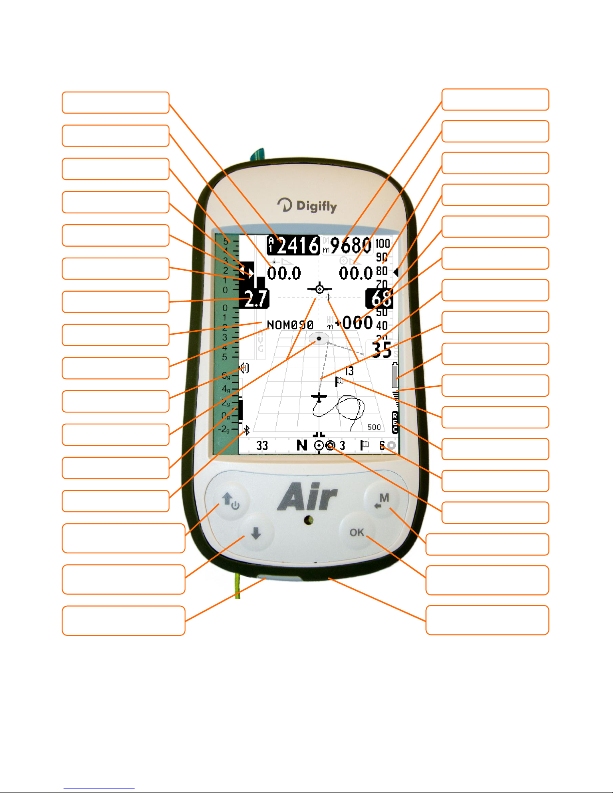
3.2 PLOTTER SCREEN
Mini USB connector
Batt. charge / PC
McCready
Digital vario
Altimeter A1
WP name
Current glide ratio
McCready equivalent
Direction to WP
center
Analogical vario scale
Analogical avg. vario
Volume level
● Contrast +
● ● Instrument On/Off
● Contrast -
● ● Volume level 1-2-Off
Bluetooth ON
Analogical G-meter
Analogical vario
Memory card slot
micro SD
Compass
Ground speed GPS
Height to WP
Optimized route to WP
Required glide ratio to the
next WP
Digital anemometer
Analogical
Anemometer
Battery level
GPS signal
Flight recorder ON
● Menu / Return
● Change page
● ● Reset altimeter A2
Distance to WP
Optimal spd to fly STF
Direction symbols
Wind direction /speed

Page 11
3.3 COMPASS SCREEN
● = Normal key pressure ● ● = Long key Pressure (2 seconds)
McCready equivalent
Digital Vario
Analogical altimeter
A1 digital altimeter
McCready
Volume level
Analogical vario scale
Analogical avg. vario
Compass main points
● Contrast +
● ● Instrument On/Off
● Contrast -
● ● Volume level 1-2-Off
External compass ring
(direction to WP)
Bluetooth ON
Internal compass ring
(thermal & wind)
Analogical G-meter
Analogical Vario
Syspem, symbols
battery, GPS, recorder
GPS ground speed
Time to START
Optimal spd to fly STF
Distance to WP
Req.glide ratio to next
WP
Distance to GOAL
Analogical Anemometer
Clock
Digital anemometer
START line distance
START direction
Current glide ratio
● Menù / Return
● Change page
● ● Reset alimeter A2
Page 12
4DISPLAY
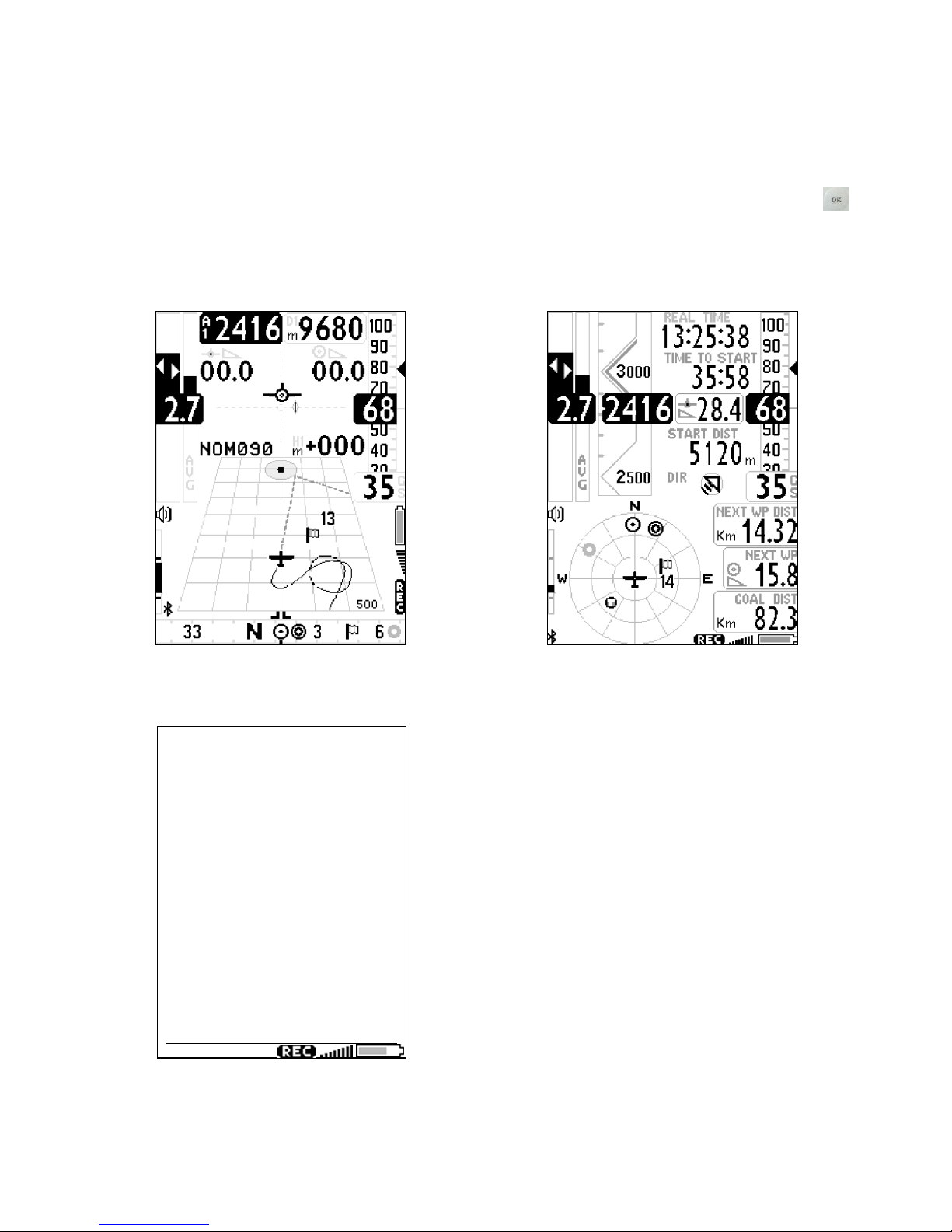
4.1 MAIN SCREENS
The Digifly Air features a lot of different main screens (page), to manually change the pages press the key.
PLOTTER PAGE
COMPASS PAGE
INFO GPS PAGE
LatLon ddmmss.ss
05 43’46.5N
005 43’46.5E
141 Tracking
00 Ground Speed
245 Altitude GPS
03/11/13 16:12:03
Page 13
4.2 PLOTTER AND COMPASS SCREENS –INSTRUMENTS FIELDS
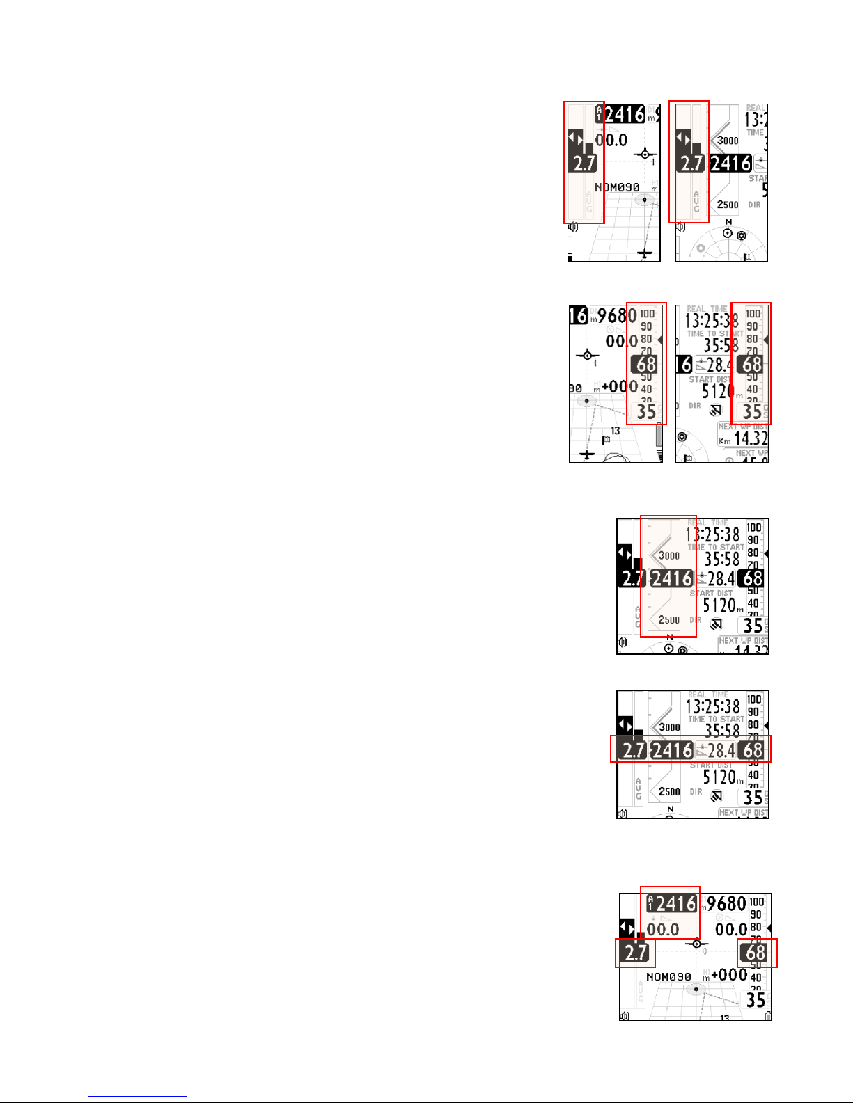
4.2.1 VARIOMETER
In the variometer’s informations area can be seen:
oDigital variometer;
oAverage vario / Netto vario;
oMc Ready value;
oMc Ready equivalent value
4.2.2 ANEMOMETER
In the shown anemometer’s informations area can be seen:
oAnalogical gauge - roll type- of Indicated Air Speed (IAS);
oIndicated Air Speed (IAS) digital value;
oGround speed GS;
oOptimal glide speed STF;
If the optional Pitot tube is not installed, it will be shown analogically and
digitally the ground speed (GS) only.
4.2.3 GRAPHIC ALTIMETER
In the COMPASS page, the altimeter’s digital information is integrated with a
graphic sliding scale. This scale is intuitive to be understood and feature a
numeric indication of the 500 and 1000 m altitude’s gap in a graphic design that
enables, at a glance, a visual distinction of the height. It features also a simple
graduated scale for the hundreds meters.
4.2.4 COMPASS SCREEN ESSENTIAL INSTRUMENTS
In the COMPASS page the essential flight info are simply shown aligned in a
raw.
Aligned with the digital variometer you can find the altimeter A1 value, the
current glide ratio and the Indicated Air Speed (if the optional pitot tube is
installed) or the GPS ground speed
4.2.5 PLOTTER PAGE ESSENTIAL INSTRUMENTS
In the PLOTTER page, the essential info are slightly different from the compass
page, to allow the availability of a larger amount of info for the navigation.
Aligned to the digital variometer, on the display’s opposite side is located the
IAS/GS indicator, while the altimeter A1 and the glide ratio are positioned on the
left-upper side of the display.
Page 14
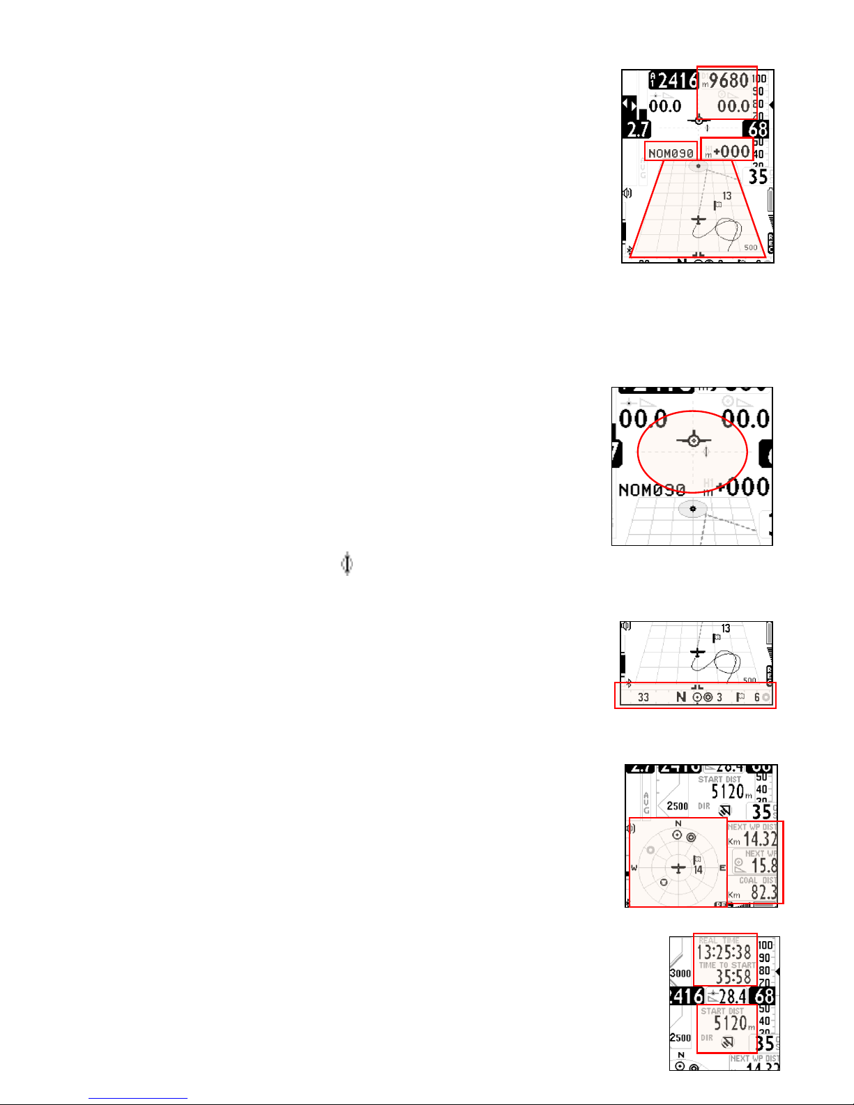
4.2.6 NAVIGATION PLOTTER SCREEN
In the PLOTTER page the navigation is based on a graphic perspective plotter that
features:
oGraphic representation of the flight track toward the current WP;
oGraphic representation of the current WP cylinder;
oOptimized course line to the current WP cylinder;
oOptimized course line to the next WP;
oWind’s direction and intensity;
The following info are listed in digital format:
oRequired glide ratio to the current WP and its distance;
oExpected height of arrival above the Current WP and current glide ratio;
oCurrent WP name.
4.2.7 HSI NAVIGATION PLOTTER PAGE
In the center of the PLOTTER page are represented two dotted lines crossed,
where the crossing point indicates the current WP with its real altitude. During
the glide to WP the “plane” symbol, moves toward the right or the left of the
vertical dotted line to indicate a wrong route to the cylinder’s center and moves
above or below the horizontal dotted line to indicate if with the current glide will
arrive above or below the WP.
Along the horizontal line, the symbol represents the optimized direction to the current WP.
4.2.8 BEARING COMPASS
On the bottom of the PLOTTER page there is a bearing compass showing also all
the navigation’s info with graphics symbols (WP direction, wind etc.…).
If the GPS signal is valid, the direction is the TRK of the GPS track, otherwise it is
represented the AIR’s internal magnetic compass.
COMPASS SCREEN MAIN FIELDS
In the COMPASS page, the navigation info are represented with a series of
concentric circles with some rotating symbols:
- Outside the circle there are the N-E-S-W points;
- In the outer ring are rotating the direction to WP symbols;
- In the inner ring are rotating the direction to the last thermal, the wind direction
and wind speed symbols.
4.2.9 COMPASS SCREEN, NAVIGATION TO THE START LINE
In the COMPASS page, during the task’s phase preceding the Start, the pilot finds some
specific info to navigate to the Start line.
On the top section there is a clock and below a field with the countdown timer to start.

Page 15
Below the glide ratio indicator is shown the distance of the Start Line closest to the pilot and its direction.
After the Start and once correctly passed the Start line, these fields can be optionally used for other info on
pilot’s choice.
5BASIC FUNCTIONS
5.1 ALTIMETERS
The Digifly AIR features 7 different altimeters: A1, A2, AG, A3, H1, HA.
-A1: Barometric altimeter.
-A2: Altimeter A2.
-AG: Altimeter GPS.
-A3: Last thermal height gain
-H1: Estimated height over current WP
-HA: Estimated height over goal.
5.1.1 ALTIMETERS SETTINGS
Enter in the “ALTIMETERS” menu and select which altimeter to set (A1 or A2).
The A2 altimeter is suitable for general purpose. To reset the A2 altimeter hold pressed the key from the
PLOTTER or COMPASS pages;
The A3 altimeter is automatically reset while entering in a thermal.
The altimeters can be displayed in meters (mt) or feet (ft). To change the altitude’s unit of measure enter the
setup from (MAIN SETUP \ n. 15 U-AL).
5.2 VARIOMETERS
5.2.1 SUPERFAST INTELLIVARIO
The Intellivario is a revolutionary digital system designed by Digifly, based on sophisticated integrated circuits
combining info coming from the atmospheric pressure sensor joined with the inertial platform data
(accelerometer, magnetometer and gyroscopes). This allows to obtain a highly precise and sensible vario,
exempt from radio interferences. All the vario data are subject to this filter.
The Digifly AIR utilizes an extremely sensible pressure sensor and an excellent data acquisition sys providing a
very quick and extremely precise vario (updated 24 times each second).
5.2.2 VARIO SENSIBILITY
Three different electronic filters are available to change the vario’s sensibility. These settings allow the pilot to
get a strong instrument’s customization, to better adapt it to his flight habits and needs.
Filter 1, adjustable in the menu (VARIOMETER SETUP \ n. 10 FLT1), default value 80% , suggested use range
from 70% to 95%, reducing this value makes the vario very sensible to variations.
Filter 2, adjustable in the menu (VARIOMETER SETUP \ n. 11 FLT2), default value 72, suggested use range

Page 16
from 48 to 96, reducing this value makes the vario very sensible to variations.
Filter 3, adjustable in the menu (VARIOMETER SETUP \ n. 12 FLT3), default value 0%, suggested use range
from 0% to 10%, reducing this value makes the vario very sensible to variations.
5.2.3 VARIO REACTIVITY
To adjust the vario’s reactivity, enter in the menu: (VARIOMETER SETUP \ n. 13 RVAR). The default value is 0.
To slow the reactivity, increase this parameter.
5.2.4 ANALOGICAL VARIO
Indicates the instant vario values. It is displayed by the analogical bar indicator on the left of the screen, it
shows the sink or climb rate within a +/- 5 m/s range.
5.2.5 INTEGRATED AVERAGE VARIO
Shows the integrated vario values. This means an average data reading (slowed down in the time) of the
instant vario.
Can be set slowed down or immediate. Setting to the minimum the integrated vario value, the shown value
will be the same of the instant vario (factory setting).
It can be used to monitor the proceeding of the climb to see if it is getting better or worse. For example: if the
integrated vario value is higher of the instant vario one, means that previously the climb was stronger. It can
be used therefore to better core the thermal.
To change the integration time, set the parameter: (VARIOMETER SETUP \ n. 14 INTE) from 0 to 60 seconds.
It is analogically displayed on the right of the instant variometer, with a bar showing the climb or sink rate with
a range +/- 5 m/s. During the glide the gauge alternates with the “NETTOVARIO”.
5.2.6 ACOUSTIC VARIO
The acoustic vario represents the instantaneous values of the vario with a modulated acoustic tone.
Pressing the key (long pressure) the sound’s volume changes into three levels: “HIGH”, “OFF” & “LOW”.
The chosen volume is shown by the ‘loudspeaker’ icon on the center left of the display.
To set the sound’s threshold level to indicate lift, go to parameter (VARIOMETER SETUP \ n. 1 V.UP), for the
sink, go to (VARIOMETER SETUP \ n. 3 V.DN).
It is possible to set the preferred acoustic profile with the parameter (VARIOMETER SETUP \ n. 4 PROF). Three
pre-set profile are available: FAS, STD, SFT, Two fully customizable profile: USR1, USR2 are available via PC
using the AirTools software; moreover, there is a new manual ‘MAN’ mode, that allows to directly customize
the instrument using the following parameters.
Style, (VARIOMETER SETUP \ n. 5 STYL) relation among sound/pause, values from 1 to 3.
Modulation, (VARIOMETER SETUP \ n. 6 MODH) increases the tone frequency from 1 to 30 Hz.
Pitch, increases ascending the tones rhythm (VARIOMETER SETUP \ n. 7 PITC) values from 1 to 4.
Climb start tone’s frequency (VARIOMETER SETUP \ n. 8 UPHZ)
Sink start tone’s frequency (VARIOMETER SETUP \ n. 9 DWHZ)
Autosilence, (VARIOMETER SETUP \ n. 19 AUTV) activates the acoustic vario only after the takeoff and stops it

Page 17
60 seconds after the landing.
5.2.7 ACOUSTIC VARIO PRE-THERMAL ADVIDSE
If activated, an acoustic signal with a tone and modulation significantly different of the acoustic vario,
indicates that the instantaneous sink rate is better of the glider’s minimum sink rate, therefore indicating an
area of slightly climbing air. To set the pre-thermal sound’s start threshold go to: (VARIOMETER SETUP \ n. 2
V.PT) value from 0,00 to 1,00 m/s. Suggested value 0,4 m/s.
5.2.8 VARIO SIMULATOR
For a perfect tuning of the acoustic vario without flying, it is possible to set the ‘vario simulator’ mode, setting
“ON” the parameter (VARIOMETER SETUP \ n. 18 SIMV). Then exit from menu and use the arrow keys
to set the preferred vario sound.
To deactivate the simulator set to “OFF” the parameter “SIMV”. Anyway, for safety reasons the simulator is
automatically deactivated when the instrument power on.
5.3 AIR SPEED (ANEMOMETER WITH OPTIONAL PITOT TUBE)
This sensor measures the glider’s air speed (Indicated Air Speed) that can be visualized in km/h or mph. To
change this parameter use the menu (MAIN SETUP \ n. 16 U-SP).
This function is available only installing the Pitot tube sensor module (optional). The tube will have to be
inserted in the specific housing hole located on the instrument’s top, and the parameter (ADVANCED SETUP \
n. 1 PITO) have to be set to “ON”.
The minimum speed indication is 18 km/h.
5.4 ANEMOMETER SETTING (WITH OPTIONAL PITOT TUBE)
It is possible to perform a fine tuning of the anemometer using the parameter (ADVANCED SETUP \ n. 3 KIAS)
it indicates the anemometer’s correction value (100%=no correction, 110%=increase, 90%=decrease).
Warning: a wrong use of this parameter makes less reliable the anemometer’s indications, the calibration of
the anemometer with the Pitot tube should have done at the sea level in standard atmosphere conditions.
5.5 TIME & CHRONOGRAPH
The Digifly AIR can visualize the expected hour and time referred to a route’s waypoint, or a goal arrival.
Relative time (hour/min or min/sec with blinking points)
-ero: relative time –expected arrival time to the start pylon cylinder shown in seconds. Negative value if it’s
too early (wrong), positive value if it’s late (right).
-es: countdown to the start time gate
-e1: expected arrival time to the current Waypoint
-eA: expected arrival time to the goal (accordingly to the route)
-ch: chronograph

Page 18
Absolute time (hour/min)
-ts: absolute time to start pylon gate
-t1: Expected absolute time to the current Waypoint.
-tA: Expected absolute time to goal.
-rt: Absolute time UTC (hours/min).
5.6 DISTANCES
It is possible to set the distance’s unit of measure using the parameter (MAIN SETUP \ n. 16 U-SP) the same
used also for the speed value.
-dstT: Distance to last thermal.
-dst1: Distance to last Waypoint.
-dstA: Distance to goal (along the route).
-dst0: Distance to the cylinder
5.7 AIR EFFICIENCY (GLIDE RATIO)
-efrT: Needed glide ratio to the last thermal.
-efr1: Needed glide ratio to current Waypoint.
-efrA: Needed glide ratio to goal (along the route).
-effA: Glide ratio referred to air.
5.8 TRACKING & BEARING
-BRT: Direction (bearing) to last thermal.
-BR0: Direction (bearing) to the center of the currrent Waypoint.
-BR1: Direction (bearing) to the optimized point of current Waypoint.
-TRK: Tracking (current direction referred to North)
5.9 BAROMETER
The barometric pressure can be visualized on every one of the customize fields.
It is possible to rectify the shown pressure value modifying the calibration with the parameter (ADVANCED
SETUP \ n. 4 KBAR).
Warning: a wrong use of this parameter makes the barometric altimeter data less reliable.
5.10 TIME/CHRONOGRAPH SETUP
rt: UTC time (clock).
ch: Chrono (chronometer).
To zero the chronograph, press the (long press).

Page 19
The vario time and date are automatically synchronized with the GPS data at the instrument’s power on.
To set the time zone for your country go to (MAIN SETUP \ n. 7 UTCO).
To manually adjust the time and date, go to (MAIN SETUP \ n. 8 HOUR), (MAIN SETUP \ n. 9 MIN), (MAIN
SETUP \ n. 10 DAY), (MAIN SETUP \ n. 11 MONT), (MAIN SETUP \ n. 12 YEAR).
5.11 PILOT’S NAME & GLIDER’S DATA
To set the pilot name, the glider type and the glider id, go to (MAIN SETUP \ n. 17 PILO), (MAIN SETUP \ n. 18
GTYP), (MAIN SETUP \ n. 19 GID).
6ADVANCED FUNCTIONS
6.1 TOTAL ENERGY COMPENSATION
To use this function it is necessary to install the optional Pitot tube.
Generally a variometer works as follows: it feels the atmospheric pressure change rate considering it as an
altitude change, but, if during the flight the pilot slows the glider (and even more if he does it quickly) there is
a real change of pressure, so a vario ‘without compensation’ records it as a climb, but this variation is caused
by a change of speed (cinetic energy) not a true thermal.
With the total energy compensation, the part of the climb due to the change in velocity is ignored, allowing you
to identify “real” thermals.
To properly set the TOTAL ENERGY
compensation value go to (VARIOMETER
SETUP \ n. 17 TEC), to do it you should fly in
calm air conditions and slow down as if you
are entering a thermal. If the vario shows a
change in lift, you have to increase the total
energy compensation value, until the
change in velocity isn’t recorded as lift.
A typical value for hang gliders is 65. The default setting of “0” deactivates the total energy compensation
function
6.2 POLAR (WITH OPTIONAL PITOT TUBE)
A polar curve (shown in bold on the figure) is the graph of
your glider’s sink rate over its speed range.
The black bold curved line represents the polar. The
glider’s stall speed is shown at point S on the left and the
glider’s max speed at point Ton the right of the graph.
On the graph, you can also see three pairs of relative
speed readings and sink rates. The graph shows at point A,
the lowest sink rate achieved at the top of the curve.
Therefore SinkA is the minimum sink rate and VA is the speed at which this is achieved.

Page 20
The glide ratio is the ratio between the glider’s horizontal speed and the sink rate. To find the best glide rate
on the graph, it is necessary to draw a straight line from the origin of the graph (point O) tangent of the curve.
The intersection of the tangent with the curve (point B) shows the speed to fly at to achieve the best glide (air
related) is therefore VB and the glide ratio is VB/SinkB.
On your Digifly AIR you can insert three different polars using the function (ADVANCED SETUP \ n. 10 - 18 Px-
A/B/C). To choose which polar to use, go to (ADVANCED SETUP \ n. 9 POLA).
If this parameter (ADVANCED SETUP \ n. 6 POLA) is set to “OFF”, all information relating to McCready,
McCready Equivalent, and Netto Vario are not displayed on the instrument.
On the instrument there are three preloaded polars, (2 for hang gliders and 1 for a paraglider). Using the
Digifly AirTool software, available on the Digifly web site (www.digifly.com), it is possible to see the values of
the three default polars and to set your own polar.
We suggest that you insert your own polar curve data which best reflects the actual performance of your
glider.
6.3 SPEED TO FLY (WITH OPTIONAL PITOT TUBE)
If this parameter (ADVANCED SETUP \ n. 9 POLA) is set to “OFF”, all information
related to McCready, McCready Equivalent, and Netto Vario are not displayed
on the instrument.
Speed to Fly (STF) is the best anemometric speed to obtain the best glide ratio.
This value depends on performance of your glider as well as vertical and
horizontal airflow. In calm air, the optimum flying speed is the same as the best
glide speed (point B).
The diagram shows different values of speed to fly value related to different
flight conditions
The X-axis shows horizontal speed, the Y-axis shows sink rate. With head wind or sink conditions, the best
glide speed increases. In order to find the optimum speed to fly value in sink conditions, add the sink rate of
the air to the polar of your glider, drawing a new polar and a new tangent line from the initial point of axes.
The new tangent (point D) meets the polar at the point giving a higher optimum flying speed VD.
To fly at the correct “Speed to fly” you have to adjust your anemometric speed “IAS” to overlap the triangle
symbol with the numeric value of the optimal anemometric speed.
Speed to Fly
Optimal STF
indicator
position
Table of contents
Other Digifly GPS manuals


