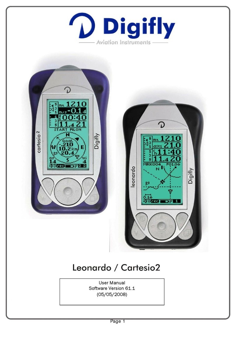
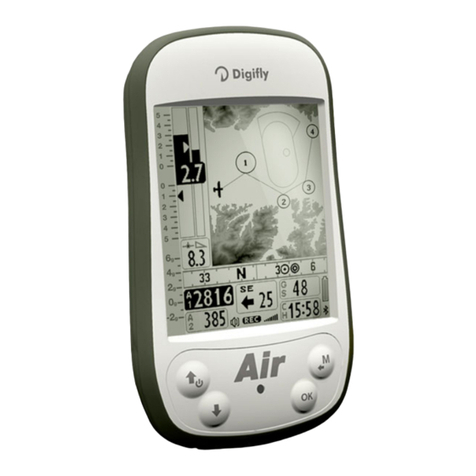
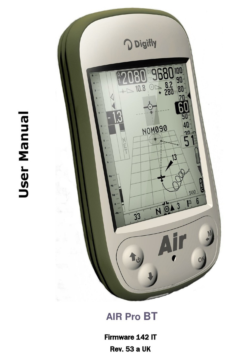
Digifly Cartesio plus User manual

C a r t e s i o plus -C a r t e s i o Pro BT
L e o n a r d o Pro - L e o n a r d o Pro BT
Version 1.3 UK (18/9/2008)
User manual

Page 2
CONGRATULATIONS
Thank you for choosing Digifly!
You have purchased a high technology instrument designed expressly for free flight. The
multiple functions and flight data it provides, effectively make it an on board computer.
Learning to use this instrument will make your flying easier in terms of performance and
safety. It will enable you to improve your flying technique and make piloting decisions more
quickly thanks to the comprehensive flight information that is provided. Another benefit is the
ability to download and analyze your flight data afterwards. Our designers can foresee future
software developments, so the software at the heart of this instrument can be updated at any
time via the Internet using the optional Digifly PC cable.
DIGIFLY INTERNATIONAL GUARANTEE
Dear Customer,
Thank you for purchasing this Digifly product which has been designed and manufactured to
the highest quality standards. Digifly warrants this product to be free from defects in materials
and workmanship for 3 years from the date of purchase.
The Digifly guarantee applies provided the product is handled properly for its intended use, in
accordance with its operating instructions and upon presentation of the original invoice or
cash receipt, indicating the date of purchase, the dealer’s name, the model and the serial
number of the instrument. The customer is however, responsible for any transportation costs.
The unit must be securely packaged for return.
The Digifly guarantee may not apply if:
- The documents have been altered in any way or made illegible.
- Repairs or product modifications and alterations have been executed by unauthorized
person or service.
- Damage is caused by accidents including but not limited to lightning, water or fire, misuse or
neglect.
Digifly assumes no responsibility for special, incidental, punitive or consequential damages, or
loss of use. If your Digifly product is not working correctly or is defective, please contact your
Digifly dealer. In order to avoid unnecessary inconvenience, we advise you to read the
operating instructions carefully before contacting your dealer.
Digifly Europe s.r.l.
Via Stradelli Guelfi 53
40138 Bologna – Italia
Tel. +39 051 533777
Internet: www.digifly.com

Page 3
1INDEX
1INDEX............................................................................................................................................................... 3
2GETTING STARTED .......................................................................................................................................... 8
2.1 GUIDE TO SOCKETS .....................................................................................................................................8
2.2 BATTERIES....................................................................................................................................................8
2.2.1 BATTERY TYPES ( "PRO" MODELS )....................................................................................................8
2.2.2 BATTERY TYPES ( "PLUS" MODEL ).....................................................................................................8
2.2.3 BATTERY LIFE ( "PRO" MODELS ) .......................................................................................................9
2.2.4 RECHARGING THE INTERNAL LITHIUM BATTERY ( "PRO" MODELS ) ..............................................9
2.2.5 INPUT FOR EXTERNAL POWER SUPPLY ( "PRO" MODELS )..............................................................9
2.3 NORMAL OR LONG KEY PRESS ................................................................................................................ 10
2.4 TURNING ON &OFF................................................................................................................................... 10
2.5 DISPLAY CONTRAST ADJUSTMENT .......................................................................................................... 10
2.6 MENU NAVIGATION ................................................................................................................................... 11
2.7 SETTING UP YOUR INSTRUMENT.............................................................................................................. 11
2.8 MULTI LANGUAGE HELP............................................................................................................................12
2.9 RESTORE FACTORY SETTINGS ................................................................................................................. 12
3QUICK REFERENCE GUIDES..........................................................................................................................13
3.1 THERMAL DISPLAY SCREEN..................................................................................................................... 13
3.2 GLIDE COMPASS DISPLAY SCREEN ......................................................................................................... 14
3.3 GLIDE PLOTTER DISPLAY SCREEN ........................................................................................................... 15
4DISPLAY .........................................................................................................................................................16
4.1 MAIN DISPLAY SCREENS .......................................................................................................................... 16
4.2 AUTOMATIC SCREEN SWITCHING -INTELLIFLIGHT ................................................................................. 16
4.3 GLIDE PLOTTER AND GLIDE COMPASS DISPLAY SCREENS.................................................................... 17
4.3.1 PLOT SCALE ...................................................................................................................................... 17
4.4 SUB SCREENS ........................................................................................................................................... 18
4.5 CUSTOMISABLE DATA FIELDS .................................................................................................................. 19
4.6 DISPLAYING ADDITIONAL INFORMATION RELATING TO WAYPOINT AND ROUTES ................................ 19
4.7 TIME INFORMATIONS................................................................................................................................ 20
4.8 DISTANCE INFORMATONS ........................................................................................................................ 21

Page 4
4.9 EFFICIENCY INFORMATIONS ....................................................................................................................21
4.10 TRACKING AND BEARING INFORMATION ................................................................................................ 21
4.11 DATA FIELDS SHOWN IN SEQUENCE........................................................................................................ 22
5BASIC FUNCTIONS.........................................................................................................................................23
5.1 ALTIMETER ................................................................................................................................................ 23
5.1.1 BAROMETRIC ALTIMETER (A1)........................................................................................................ 23
5.1.2 ADDITIONAL ALTIMETERS................................................................................................................ 24
5.1.3 ADJUSTING ALTIMETERS A1 AND A2.............................................................................................. 25
5.1.4 GRAPHIC ALTIMETER DISPLAY........................................................................................................ 25
5.2 VARIOMETER ............................................................................................................................................. 26
5.2.1 SUPERFAST INTELLIVARIO............................................................................................................... 26
5.2.2 VARIO REACTIVITY ............................................................................................................................ 26
5.2.3 ANALOGUE VARIO............................................................................................................................. 26
5.2.4 INTEGRATED (AVERAGED) VARIO.................................................................................................... 27
5.2.5 ACOUSTIC VARIO............................................................................................................................... 27
5.2.6 VARIO SIMULATOR ........................................................................................................................... 27
5.3 AIR SPEED (WITH OPTIONAL AIR SPEED PROBE).................................................................................... 28
5.3.1 STALL ALARM ................................................................................................................................... 28
5.3.2 AIR SPEED RECALIBRATION ............................................................................................................ 28
5.4 TEMPERATURE.......................................................................................................................................... 29
5.5 BAROMETER.............................................................................................................................................. 29
5.6 TIME /CHRONOGRAPH............................................................................................................................. 30
5.7 PILOT NAME &GLIDER DATA .................................................................................................................... 30
6ADVANCED FUNCTIONS ................................................................................................................................31
6.1 TOTAL ENERGY COMPENSATION ............................................................................................................. 31
6.2 THERMAL CENTERING FUNCTION............................................................................................................ 31
6.3 AIR EFFICIENCY (GLIDE RATIO)................................................................................................................. 32
6.4 POLAR DATA .............................................................................................................................................. 32
6.5 SPEED TO FLY............................................................................................................................................ 33
6.6 MCCREADY ................................................................................................................................................ 34
6.7 EQUIVALENT MCCREADY........................................................................................................................... 35
6.8 NETTO VARIO ............................................................................................................................................. 35

Page 5
6.9 THERMAL SNIFFER ................................................................................................................................... 36
7GPS FUNCTIONS............................................................................................................................................37
7.1 INTEGRATED 20 CHANNEL GPS RECEIVER (LEONARDO MODELS).............................................................. 37
7.2 GPS STATUS INFORMATION .....................................................................................................................37
7.3 POWER SAVING MODES (LEONARDO MODELS)............................................................................................ 37
7.4 GPS SIGNAL AND BATTERY LIFE (LEONARDO MODELS) ............................................................................... 38
7.5 GPS INFORMATION DISPLAY .................................................................................................................... 38
7.6 LATITUDE &LONGITUDE COORDINATES.................................................................................................. 38
7.7 GPS ALTITUDE ........................................................................................................................................... 38
7.8 GROUND SPEED GPS................................................................................................................................ 38
7.9 GPS DIRECTION (TRK)............................................................................................................................... 38
7.10 GROUND EFFICIENCY (GLIDE RATIO) ....................................................................................................... 38
7.11 WIND SPEED AND DIRECTION INDICATION USING GPS.......................................................................... 39
7.12 HSI GRAPHICS INDICATION....................................................................................................................... 40
7.13 LAST THERMAL INFORMATIONS (WITH GPS)........................................................................................... 40
7.14 DIRECTION, DISTANCE AND HEIGHT TO WAYPOINTS.............................................................................. 41
7.15 REQUIRED EFFICIENCY TO THE CURRENT/NEXT WAYPOINT AND TO ARRIVAL AT GOAL ...................... 42
7.16 DIRECTION TO CURRENT AND NEXT WAYPOINT...................................................................................... 42
7.17 SAFE LANDING GLIDE CONE INDICATION ................................................................................................ 42
7.18 WAYPOINT MANAGEMENT........................................................................................................................ 43
7.18.1 MANUALLY CREATE A NEW WAYPOINT.......................................................................................... 43
7.18.2 CREATE NEW WAYPOINT WITH CURRENT POSITION (MARK) ....................................................... 44
7.18.3 EDIT WAYPOINT................................................................................................................................ 44
7.18.4 DELETE WAYPOINT ........................................................................................................................... 44
7.18.5 NAVIGATE TO A WAYPOINT (GOTO) ................................................................................................ 45
7.18.6 CREATE HOME WAYPOINT ............................................................................................................... 45
7.19 ROUTE MANAGEMENT .............................................................................................................................. 45
7.19.1 INSERT WAYPOINTS IN AN EMPTY ROUTE ..................................................................................... 46
7.19.2 INSERT A WAYPOINT AT THE LAST POSITION OF THE ROUTE....................................................... 46
7.19.3 INSERT A WAYPOINT IN A ROUTE WITH WAYPOINTS.................................................................... 46
7.19.4 CHANGE WAYPOINTS IN A ROUTE.................................................................................................. 46
7.19.5 DELETE WAYPOINTS IN A ROUTE ................................................................................................... 47
7.19.6 ACTIVATE / DEACTIVATE / REVERSE / CLEAR A ROUTE ............................................................... 47
7.20 COMPETITION ROUTE ............................................................................................................................... 48

Page 6
7.20.1 SETUP THE COMPETITION ROUTE (Rt 1 Comp).............................................................................. 48
7.20.2 START PYLON NAVIGATION............................................................................................................. 50
7.20.3 FAI CYLINDER NAVIGATION.............................................................................................................. 51
7.20.4 CHANGE WAYPOINT ICON ON A COMPETITION ROUTE ................................................................. 52
7.20.5 MANUALLY JUMP TO PREVIOUS/NEXT WAYPOINT ........................................................................ 52
8FLIGHT RECORDER........................................................................................................................................53
8.1 ACTIVATING THE FLIGHT RECORDER ....................................................................................................... 53
8.1.1 AUTOMATIC START RECORD MODE................................................................................................ 53
8.1.2 ALWAYS RECORD MODE.................................................................................................................. 54
8.1.3 RECORD MODE OFF ......................................................................................................................... 54
8.2 RECORD RATE ........................................................................................................................................... 54
8.3 RECORDED ALTIMETER ........................................................................................................................... 54
8.4 LOG BOOK MANAGEMENT........................................................................................................................ 55
8.5 FLIGHT PLAYBACK..................................................................................................................................... 55
9PC CONNECTION AND INTERFACE................................................................................................................56
9.1 COMPETITION SOFTWARE COMPATIBILITY.............................................................................................. 56
9.2 CONNECTING WITH COMPEGPS, MAXPUNKTE, GPSDUMP, CHECKIN (PWC) SOFTWARE .................... 56
9.2.1 UPLOADING COMPETITION WAYPOINTS ......................................................................................... 56
9.2.2 DOWNLOAD A SINGLE FLIGHT......................................................................................................... 57
9.2.3 DOWNLOAD ALL FLIGHTS................................................................................................................ 57
9.3 CONNECTING WITH THE DIGIFLY VLTOOLS SOFTWARE.......................................................................... 57
9.4 FIRMWARE UPGRADE ............................................................................................................................... 58
9.4.1 UPGRADE PROCESS......................................................................................................................... 59
9.5 PROBLEMS CONNECTING TO YOUR PC.................................................................................................... 60
9.6 TELEMETRY OUTPUT................................................................................................................................. 62
9.6.1 BLUETOOTH TELEMETRY OUTPUT .................................................................................................. 62
9.7 EXTERNAL GPS CONNECTION (CARTESIO MODELS) .................................................................................... 63
10 APPENDIX ......................................................................................................................................................64
10.1 DIGIFLY CARTESIO PLUS STANDARD ACCESSORIES .............................................................................. 64
10.2 DIGIFLY CARTESIO PRO BT -LEONARDO PRO STANDARD ACCESSORIES ............................................. 64

Page 7
10.3 OPTIONAL ACCESSORIES.......................................................................................................................... 64
10.4 DIGIFLY TECHNICAL FEATURES................................................................................................................ 64
10.5 STANDARD FUNCTIONS............................................................................................................................ 64
10.6 ADVANCED FUNCTIONS ............................................................................................................................ 65
10.7 GPS FUNCTIONS........................................................................................................................................ 65
10.8 GENERAL SPECIFICATIONS ...................................................................................................................... 65
10.9 MAIN SETUP PARAMETERS ......................................................................................................................67
10.10 ADVANCED SETUP (ADV-SETUP) PARAMETERS....................................................................................... 68
10.11 RESTORE FACTORY SETTINGS ................................................................................................................. 68
10.12 DATA FIELDS SHOWN IN SEQUENCE........................................................................................................ 69
10.13 THERMAL DISPLAY SCREEN..................................................................................................................... 70
10.14 GLIDE COMPASS DISPLAY SCREEN ......................................................................................................... 71
10.15 GLIDE PLOTTER DISPLAY SCREEN ........................................................................................................... 72

Page 8
2GETTING STARTED
2.1 GUIDE TO SOCKETS
2.2 BATTERIES
2.2.1 BATTERY TYPES ( "PRO" MODELS )
The Digifly instrument "PRO" models (Cartesio Pro BT , Leonardo Pro and Leonardo Pro
BT ) are supplied with a high power, fully independent, automatic double battery system:
The main power is supplied by an internal rechargeable lithium battery (supplied as
standard) with a full recharge time of only 3 hours. This battery has no memory effect,
so it can be partially recharged, it also has a very low self discharge rate (more than one
year) and works very well at low temperatures. Battery life ranges from 30 hours to 200
hours depending on whether GPS or Bluetooth has been activated.
The backup battery is a high power non-rechargable 1.5 volt AA size battery. This battery
is situated in the removable battery "slot" and can also be replaced with other 1.5 volt
AA size batteries. To change this battery you will need a flat-blade screwdriver to
unscrew the battery cover on the rear of the vario. Rechargeable batteries can be used,
though are not recommended for the backup battery system because of their high self
discharge rate (after 2 months they are completely discharged and useless). If using a
rechargable backup battery, note that this battery is not recharged by the instrument
but has to be removed and recharged externally by the user. The backup battery life
ranges from 20 hours to 200 hours depending on whether GPS or Bluetooth has been
activated
2.2.2 BATTERY TYPES ( "PLUS" MODEL )
The Cartesio Plus model has only one non-rechargable 1.5 volt AA size battery. This
battery is situated in the removable battery "slot" and can also be replaced with other
1.5 volt AA size batteries. To change this battery you will need a flat-blade screwdriver to

Page 9
unscrew the battery cover on the rear of the vario. Rechargeable batteries can be used,
though are not recommended because of their high self discharge rate (after 2 months
they are completely discharged and useless). If using a rechargable backup battery,
note that this battery is not recharged by the instrument but has to be removed and
recharged externally by the user. The battery life is about 200 hours.
2.2.3 BATTERY LIFE ( "PRO" MODELS )
the Digifly instruments "PRO" models (Cartesio Pro BT , Leonardo Pro and Leonardo Pro
BT) can achieve 30 hours use (main internal lithium battery) + 20 hours use (removable
backup battery) under optimal conditions.
When the battery icon starts to blink there are less than 5 hours use remaining .
2.2.4 RECHARGING THE INTERNAL LITHIUM BATTERY ( "PRO"
MODELS )
With the instrument turned off, insert the Digifly Wall Adapter
Recharger plug in to the left socket of your Digifly flight
instrument.
The vario display shows the blinking message “CHARGE”
while charging and "LITIO FULL" when fully charged.
The time required for a full recharge is about 3 hours.
There is no problem if you leave the vario charging for more
than 3 hours , as the vario automatically switches to a
“maintain mode” to prevent any damage from occurring due
to overcharging the battery.
With Lithium batteries, there is no “memory effect”, so you may also partially charge the
main Lithium battery.
2.2.5 INPUT FOR EXTERNAL POWER SUPPLY ( "PRO" MODELS )
With the instrument turned on is possible to use an external stabilized 5VDC power
supply (e.g. a solar panel). A minimum of 150mA current is required to power the
instrument. If more current is available from the power source it will be used charge the
internal lithium battery .

Page 10
2.3 NORMAL OR LONG KEY PRESS
The length of time a key is pressed on your Digifly instrument influences the functions
available.
For a normal key press, you must press the button for less than a second.
For a long key press, you must keep the button pressed down for at least 2 seconds.
When not specified, the key press is to be considered as a normal key press (less than a
second).
2.4 TURNING ON & OFF
To turn on your Digifly instrument, press the key at least for 4 seconds.
To turn off your Digifly instrument, press the key at least for 4 seconds.
After switching off your Digifly instrument, you must wait at least 5 seconds before you
can turn it on again. This prevents unwanted operation e.g. during transit in your glider
bag.
After turning your Digifly instrument on, the first screen briefly shows the vario model,
pilot name (if set), vario serial number, software version, date and time and battery
voltage.
2.5 DISPLAY CONTRAST ADJUSTMENT
The contrast of the Digifly instrument LCD display can be adjusted to suit ambient light
conditions.
To change the contrast of the display, go to (MAIN SETUP \ n. 1 CTRS), press the
key (function “EDIT”) to go to the edit mode and then press the arrow keys , to
increase or decrease the display contrast.

Page 11
2.6 MENU NAVIGATION
To navigate the menus on your Digifly instrument, go to the MENU
page by pressing the key (function “men”).
To return to the instrument’s main display, press the key
(function “ESC”).
From the “MENU” page, to select the sub-menus, move up and down
using the arrow keys , and to confirm, press the key
(function “ENT”).
To change the selected parameter’s values, use the arrow keys , and confirm
with the key (function “SAV”) or you can also leave without saving your edit with
the key (function “ESC”).
2.7 SETTING UP YOUR INSTRUMENT
To setup your Digifly instrument and adjust the
parameters mentioned in the following sections, go
to the MENU page by pressing the key
(function “men”).
There are two setup menus on the Digifly
instrument. The “MAIN SETUP” menu and the
“ADVANCED SETUP” menu.
Using the arrow keys , scroll to select the “MAIN SETUP” or the “ADVANCED
SETUP” menu and to select, confirm, press the key (function “ENT”).
You will now see a list of parameters that can be adjusted in the “MAIN SETUP” there
are 32 parameters that can be adjusted. In the “ADVANCED SETUP” there are a further
20 parameters that can be adjusted.
To change parameters, select the parameter you want to change, move up and down
with the arrow keys , . Press the key (function “EDIT”) to go to the edit
mode.

Page 12
To change the selected parameter’s values, use the arrow keys , and confirm
with the key (function “SAV”) or you can also leave without saving your edit with
the key (function “ESC”).
To return to the instrument’s main display, press the key (function “ESC”).
2.8 MULTI LANGUAGE HELP
To help you setup your Digifly instrument, the instrument supports several help
languages. To change the help language go to (MAIN SETUP \ n. 32 LANG) & select the
language of choice
When updating the software on the Digifly instrument, make sure you upload the latest
help file for the language you have selected, using the “upload HELP” function of the
Digifly Vltools software on your PC.
2.9 RESTORE FACTORY SETTINGS
To restore the factory settings (default values for all parameters), press and hold down
the key as you turn vario on. Keep the key pressed until a message “FACTORY
SET?” appears, then confirm with “YES” or “NO”. If you select “YES”, a confirming
message “SETUP RESET” is shown.

Page 13
3QUICK REFERENCE GUIDES
3.1 THERMAL DISPLAY SCREEN
Volume Level - Flight Recorder - Bluetooth Link - Battery State - GPS Signal - Subpage
Altimeter A1
Blank
(customisable data field)
Equivalent McCready
McCready
Analogue Vario
●Scroll Subpage
●●Volume Off/Med/High
●Go To Waypoint
●●Skip to next start gate
●Scroll data field / Zoom-
●●Jump to prev. WP
●On/Off GPS antenna
●●On/Off Instrument
●Info / Edit display data field
●●Graphic Altimeter / Thermal Centering ●MENU
●●GPS Info/Mark WP
●Scroll data field / Zoom+
●●Jump to next WP
●Scroll Page
●●Zero Chronograph
●Info / Edit display data field
●●Zero A2 Altimeter
●= Normal key pressure ●●= Long key pressure (2 seconds)
Graphic Altimeter /
Thermal Centering
Altimeter A2
(customisable data field)
Inte
g
rated Vario
Clock UTC
(customisable data field)
Efficiency - Ground speed
(customisable data field)

Page 14
3.2 GLIDE COMPASS DISPLAY SCREEN
Volume Level - Flight Recorder - Bluetooth Link - Battery State - GPS Signal - Subpage
Wind Speed
Informations Index
(customis. data field)
Wind Direction
McCready
Analogue Vario
●Scroll Subpage
●●Volume Off/Med/High
●Go To Waypoint
●●Skip to next start gate
●Scroll data field / Zoom-
●●Jump to prev. WP
●On/Off GPS antenna
●●On/Off Instrument
●Info / Edit display data field
●●Graphic Altimeter / Thermal Centering ●MENU
●●GPS Info/Mark WP
●Scroll data field / Zoom+
●●Jump to next WP
●Scroll Page
●●Zero Chronograph
●Info / Edit display data field
●●Zero A2 Altimeter
●= Normal key pressure ●●= Long key pressure (2 seconds)
Altimeter A1
(customisable data field)
Current WP name
Estim. Time to Next WP
(customisable data field)
Efficiency - Ground speed
(customisable data field)
Required Effic. to Next WP
Distance to Next WP
Altitude to Next WP
North Direction
Equivalent McCready
Last Thermal Direction
Current WP Direction
Integrated Vario
(customisable data field)
Next WP Direction
GPS Ground Speed

Page 15
3.3 GLIDE PLOTTER DISPLAY SCREEN
Volume Level - Flight Recorder - Bluetooth Link - Battery State - GPS Signal - Subpage
Last Thermal Direction
Wind Direction
Equivalent McCready
Analogue Vario
●Scroll Subpage
●●Volume Off/Med/High
●Go To Waypoint
●●Skip to next start gate
●Scroll data field / Zoom-
●●Jump to prev. WP
●On/Off GPS antenna
●●On/Off Instrument
●Info / Edit display data field
●●Graphic Altimeter / Thermal Centering ●MENU
●●GPS Info/Mark WP
●Scroll data field / Zoom+
●●Jump to next WP
●Scroll Page
●●Zero Chronograph
●Info / Edit display data field
●●Zero A2 Altimeter
●= Normal key pressure ●●= Long key pressure (2 seconds)
Altimeter A1
(customisable data field)
Current WP name
Clock UTC
(customisable data field)
Efficiency - Ground speed
(customisable data field)
HSI Bearing to curr. WP
FAI Cylinder
Course Predictor
North Direction
McCready
HSI Height over curr. WP
Current WP Direction
Integrated Vario
(customisable data field)
Next WP Direction
Plotter scale 10pix/km
Pilot Location

Page 16
4DISPLAY
4.1 MAIN DISPLAY SCREENS
The are 3 main display screens on the Digifly instrument:
-The Thermal Display , the Glide Compass Display and the Glide Plotter Display.
To manually switch between these 3 main display screens, press the key.
THERMAL DISPLAY
GLIDE COMPASS DISPLAY
GLIDE PLOTTER DISPLAY
4.2 AUTOMATIC SCREEN SWITCHING - INTELLIFLIGHT
The Intelliflight function handles the automatic screen
switching between the Thermal Display screen and Glide
Compass Display or Glide Plotter Display screens.
To enable this function go to (ADVANCED SETUP \ n. 1 IFLY)
and set it to “ON”.
The Digifly instrument will switch automatically to the
Thermal Display screen when the conditions of a thermal are
met.
To set the thermal detection parameters, go to (ADVANCED
SETUP \ n. 2 THEV) and (ADVANCED SETUP \ n. 3 THET) to adjust the vertical speed
(vario) and for how many consecutive seconds this vertical speed has to be detected.
The instrument will then switch back to the Glide Compass or Glide Plotter display
screens when there is no lift for more than 10 seconds.

Page 17
4.3 GLIDE PLOTTER AND GLIDE COMPASS DISPLAY SCREENS
The Glide Plotter display shows
essential vario information along with a
live graphical trace of your flight,
Waypoints & Route information and
wind direction.
The Glide Compass Display screen
shows essential vario information along
with a compass, showing Waypoints &
Route information, thermal location,
efficiency information, ground speed , wind speed and wind direction.
For some of these function to be active, Waypoints must have been entered in to the
Digifly instrument and a Route activated and a GPS “FIX” achieved.
4.3.1 PLOT SCALE
To zoom in or out of the live plot of your
flight, press the arrow keys ,
The plot scale is shown on the left of
the screen according to the following
values:
Valore ZOOM
Km/schermo m/pixel
0.01 0.06 1
0.02 0.125 2
0.04 0.25 4
0.08 0.5 8
0.16 1 16
0.32 2 32
0.64 4 65
1.28 8 130
2.56 16 250
5.12 32 500
10.2 65 1000
20.4 130 2000
40.9 250 4100

Page 18
4.4 SUB SCREENS
On each of the main display screens (the Thermal Display screen, Glide Compass
Display screen and Glide Plotter Display screens) there are 3 fully customizable sub
pages, a total of 9 sub-pages already setup and configured with information related to:
To scroll between the each sub-page, press the key.
Sub-page "1" is preset with all information related to the WP1 (the current Waypoint)
and is easily recognized by the icon "1" on the display status bar
Sub-page "2" is preset with all information related to the WP2 (the next Waypoint ) and
is easily recognized by the icon "2 2" on the display status bar.
Sub-page "3" is preset with all information related to the arrival Waypoint (GOAL) and is
easily recognized by the icon "GOL" on the display status bar.
Current Waypoint Next Waypoint Arrival Waypoint

Page 19
4.5 CUSTOMISABLE DATA FIELDS
It is possible to customise the pre-set screens.
On the Thermal Display Screen there are 5 data fields (highlighted here in red) that can
be customized to change the type of data to be displayed.
On the Glide Plot and Glide Compass Display Screens all 4 main data fields (highlighted
here in red) that can be customized to change the type ofdata to be displayed.
On the Glide Compass Display screen the inner triple instrument reference can also be
customized to display WP1, WP2, GOAL or Thermal.
To change the data shown in this field, press the ,keys to highlight the field you
wish to adjust.
As you scroll up or down, the fields that you can customize are highlighted (inverted)
and for approximately 3 seconds a description of the data currently being displayed is
shown.
To change the data you wish to display, press the ,keys. Each time a new
parameter is selected, the field shows the a description of the data currently selected.
4.6 DISPLAYING ADDITIONAL INFORMATION RELATING TO WAYPOINT AND ROUTES
For these functions to be active, Waypoints must have been entered in to the Digifly
instrument, a Route activated, the GPS switched “ON”, a GPS “FIX” made,”.
The additional data relating to Waypoints and routes can be shown in any of the
customizable data fields (shown here in red) on each of the main display screens
(Thermal Display screen, Glide Compass Display screen and Glide Plotter Display
screen)

Page 20
To show additional information in any of these customizable fields, press the ,
keys to highlight & select the data field you wish to adjust.
As you scroll up or down, the fields that you can customize are highlighted (inverted)
and a description of the data currently being shown is that field is shown for approx 3
seconds.
To change the data you wish to display, press the ,key. Each time the data field
is changed, the field briefly shows a description of the data type currently selected.
4.7 TIME INFORMATIONS
The Digifly instrument can display time information related to Waypoints and Routes:
-ero:Estimated relative time related to start gate time in seconds, negative = advance
(wrong) / positive = delay (correct).
-es:Remaining time to start pylon gate open.
-e1:Estimated remaining time to current Waypoint.
-e2:Estimated remaining time to next Waypoint.
-eA:Estimated remaining time to goal.
-ts:Start pylon absolute time .
-t1:Estimated time to current Waypoint.
-t2:Estimated time to next Waypoint.
-tA:Estimated time to Goal.
-rt: UTC Time.
-ch: Chronograph.
This manual suits for next models
3
Table of contents
Other Digifly GPS manuals
