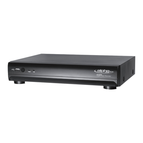
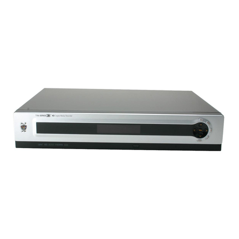
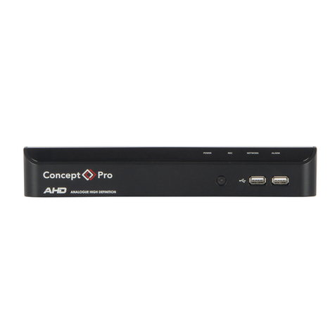
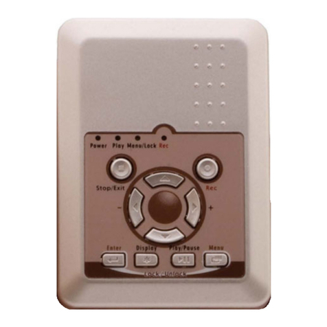
Digiguard H.264 Digital video recorder -4/8/16 channel... User manual

Ver 1.400

INSTALLATION & SAFEGUARDS
All the safety and operating instructions should be read before operation.
Environment Condition for Installation
1. To prevent electric shock or other hazard, do not expose this unit to rain, moisture, or dust.
2. Place this unit in a well-ventilated place and do not place heat-generating objects on this unit.
3. This unit should not be located in an area where it is likely to be subjected to mechanical shocks.
Before You Start
1. Ensure the power switch is in the OFF position prior to installation.
2. Opening or removing the cover may expose you to dangerous voltage or other hazards.
3. Operate this unit within the range of room temperature and humidity.
4. Supply power through the type of power source indicated on the manufacturer’s label and with the
power supply included in this unit.
5. Keep this unit out of direct sunlight and heat .
6. Make sure conductive material does not go into the fan hole.
Notice
1. Before initial configuration or operation, first set TIME/DATE, and then set this unit to the
FACTORY DEFAULT setting, and lastly HDD clear. Follow these steps in order. Otherwise it may
cause non-recording on the HDD or non saving setting value. Or it may record, but you will not be
able to search recorded data.
2. This unit is compatible with large sized HDD.
3. When setting RECORDING SETUP after installation, set not only RECORD CONFIGURATION,
but also SCHEDULE SETUP. Setting Schedule setup is necessary as this unit records according to
Record type & Schedule setup. Default setting value for Schedule setup is Continuous mode.
4. Stop recording before powering off this unit by entering setup menu. Powering off while recording
may cause critical malfunctions such as Recording Error, Playback Error, or System Error.
FCC Information
This equipment has been tested and found to comply with the limits for a Class A digital device,
pursuant to part 15 of the FCC Rules.
These limits are designed to provide reasonable protection against harmful interference when the
equipment is operated in a commercial environment.
This equipment generates, uses, and can radiate radio frequency energy and, if not installed and
used in accordance with the instruction manual, may cause harmful interference to radio
communications.
Operation of this equipment in a residential area is likely to cause harmful interference in which case
the user will be required to correct the interference at his own expense.
Changes or modifications not expressly approved by the party responsible for compliance could void
the user's authority to operated the equipment under FCC rules.
2

Table of Contents
CHAP. 1 General Information ---------------------------------------------------------------- 4
1-1. Package Contents &
Description ---------------------------------------------------------------- 5
CHAP. 2 Function of Buttons ---------------------------------------------------------------- 6
2-1. Front Panel ---------------------------------------------------------------- 6
2-2. Rear Panel ---------------------------------------------------------------- 8
CHAP. 3 Installation ---------------------------------------------------------------- 10
3-1. Configuration ---------------------------------------------------------------- 10
3-2. Detailed Configuration ---------------------------------------------------------------- 11
1) Rack Mount ---------------------------------------------------------------- 11
2) HDD (Hard Disk Drive) ---------------------------------------------------------------- 11
3) Camera ---------------------------------------------------------------- 13
4) Audio ---------------------------------------------------------------- 13
5) Monitor ---------------------------------------------------------------- 14
6) Power Cable ---------------------------------------------------------------- 14
7) SPOT, Video Printer ---------------------------------------------------------------- 14
8) Others ---------------------------------------------------------------- 15
CHAP. 4 Display Configuration ---------------------------------------------------------------- 17
4-1. Display ---------------------------------------------------------------- 18
4-2. Channel ---------------------------------------------------------------- 18
4-3. Menu ---------------------------------------------------------------- 19
4-4. Record, Playback Toolbar ---------------------------------------------------------------- 23
4-5. Panic Recording ---------------------------------------------------------------- 23
4-6. Search ---------------------------------------------------------------- 24
4-7. PTZ control ---------------------------------------------------------------- 25
4-8. CD/DVD Backup ---------------------------------------------------------------- 25
4-9. USB Backup ---------------------------------------------------------------- 26
CHAP. 5 Operation ---------------------------------------------------------------- 27
5-1. System Login ---------------------------------------------------------------- 27
5-2. Factory Default ---------------------------------------------------------------- 27
5-3. Access Authority ---------------------------------------------------------------- 28
5-4. Key Lock ---------------------------------------------------------------- 28
5-5. Playback (Search) ---------------------------------------------------------------- 29
3

CHAP. 6 DVR Setup ---------------------------------------------------------------- 30
6-1. General Operation ---------------------------------------------------------------- 30
6-2. Configuration ---------------------------------------------------------------- 31
6-3. Display ---------------------------------------------------------------- 34
6-4. HDD Management ---------------------------------------------------------------- 35
6-5. Camera ---------------------------------------------------------------- 36
6-6. Record ---------------------------------------------------------------- 39
6-7. Backup/Update ---------------------------------------------------------------- 39
6-8. Network ---------------------------------------------------------------- 41
6-9. Language ---------------------------------------------------------------- 43
CHAP . 7 Network Setup ---------------------------------------------------------------- 44
7-1. DVR Network ---------------------------------------------------------------- 44
7-2. DDNS ---------------------------------------------------------------- 46
7-3. Web Application ---------------------------------------------------------------- 47
CHAP. 8 Remote Viewer Program ---------------------------------------------------------------- 48
8-1. IRS Operation ---------------------------------------------------------------- 48
8-2. Backup Operation ---------------------------------------------------------------- 51
8-3. Transmitter Operation ---------------------------------------------------------------- 53
8-4. Player Operation ---------------------------------------------------------------- 59
CHAP. 9 Specification / Dimension ---------------------------------------------------------------- 62
CHAP.10 Remote Controller ---------------------------------------------------------------- 64
4

1-1. Package Contents & Description
1. DVR Main Unit
3. Power Cable 4. Power Adapter 5. User’s Manual 6. Software CD
7. Rubber Pad 8. HDD Absorber 9. Rack Mount Bracket
HDD Bolts
Contents Description
1. DVR Main Unit Stand-Alone DIGITAL VIDEO RECORDER
2. Remote Control Remote Control
3. Power Cable AC power supply to adapter
4. Power Adapter DC power supply
5. User’s Manual User’s Manual
6. Software CD Remote Viewer SOFTWARE
7. Rubber Pad Prevent DVR from slipping by attaching on the bottom of the unit
8. HDD Absorber Absorbing the mechanical shock of HDD against the case bottom
9. Batteries Batteries for Remote Control
10. Rack Mount Bracket /
Bolts Rack Mount Bracket / 6 Bolts for fixing Rack Mount Bracket to DVR / 4 Bolts for
fixing DVR with Rack Mount Bracket to 19” Rack / 8 Bolts for fixing HDD into
DVR
11. Mouse DVR function control
10. Mouse
2. Remote Control
8. Batteries
1. General Information
5

2-1. Front
2. Function of Buttons
Name Function
1.LED Lamps Status of operation
2.Jog Shuttle Jog shuttle activate only when in Pause: Pressing Jog Shuttle button will pause
playback.
Rotating clockwise causes it to move into ever-faster forward speed, and counter-
clockwise causes it to move into ever-faster reverse speed.
In Setup Menu, its rotation Increases or Decreases value.
3.Function Key MENU Enter SYSTEM MENU
PANIC Panic recording at continuous mode at highest quality (120ips,
Highest, 1/1x)
BOOKMARK Check the bookmark while playback for bookmark search.
PLAY Playback recorded data on HDD
AUDIO Select audio channel. Turn volume up/down
K.LOCK Locking the key.
To unlock, keep pressing the button for a few seconds and input
password (Same password for Setup Menu)
SEARCH Search recorded data on HDD
STOP Stop Playback.
4.LIVE View
Control Key
PTZ Shift LIVE mode to PTZ control mode
MODE Switch screen division from full screen to 16 split screen (in 1, 4, 9,
13, 16 sequence )
SEQ Auto camera image sequence in full screen mode
PIP Picture In Picture mode
FRZ Freeze Live display
ZOOM Zoom image
12345
678
6

Name Function
4-1.Control Key FUNC Main menu panel On/Off
ESC Cancel selected menu panel
+ Increase setting value, page shift
- Decrease setting value, page shift
5.Arrow key Navigate in the menu
6. USB Device For Firmware upgrade and USB backup
7.Camera Selection /
PTZ Control
1~16 Button : Select camera channel in full screen mode
NEAR : FOCUS NEAR PRESET + : Increase PRESET NO.
FAR : FOCUS FAR PRESET - : Decrease PRESET NO.
WIDE : ZOOM IN PTZMENU : PTZ MENU POPUP
TELE : ZOOM OUT F1 : USER 1
SET : PRESET SET F2 : USER 2
CLEAR : PRESET CLEAR F3 : USER 3
GOTO : PRESET GOTO F4 : USER 4
AUTO : AUTO SCAN F5 : USER 5
8.CD/DVD-ROM For Firmware upgrade and CD/DVD backup
7

2-2. Rear
[Rear Panel for 4ch DVR]
[Rear Panel for 8ch DVR]
[Rear Panel for 16ch DVR]
1
2
3
4689
57
10
11
12
1
2
3
4689
57
10
11
12
1
234
689
57
10 11
12
8

Name Function
1 RS 485 Connection with PTZ Camera or other external devices using RS 485
RELAY Output Relay Output terminal
SENSOR Input Sensor Input terminal
2 VGA VGA Output to CRT or TFT LCD Monitors
3 ETHERNET Connection to Ethernet devices
4 RS-232C Connection to external devices such as PC using RS-232C to control DVR
5 Camera Input Connection with NTSC/PAL Cameras
6 Loop Out Camera Loop out
7 Monitor Output Connection with NTSC/PAL Composite Monitor
8 SPOT Output Connection from Analog backup output to external devices
9 DC Power DC 12V 6.67A Adaptor
10 PS2 Mouse Connection to PS2 Mouse
11 Audio Microphone input and Audio output
12 POWER
SWITCH Power ON/OFF Switch
To avoid accidental deletion of HDD data, please make sure to press
MENU button and enter into setup menu before powering off the unit.
This takes the unit out of recording mode for safe shutdown.
NOTE : You can not mix PAL and NTSC equipment. For example, you cannot
use a PAL camera and NTSC monitor.
9

3-1. Configuration
3. Installation
[ Typical Digital Video Recorder Installation ]
10

2
1
3
2) HDD (Hard Disk Drive) Connection
1) Rack mount
3-2. Detailed Configuration
1. Remove all 4 bolts on side caps.
2. Attach Rack mount bracket to DVR.
3. Attach DVR with rack mount bracket to 19” Rack.
1. Connect Main Board and HDD1 using IDE cable and HDD power cable.
2. When you use just 1 HDD, install the HDD onto HDD1 location.
3. When you use 2 HDDs, install the first HDD onto HDD1 location and then install the second HDD
onto HDD2 location in order.
4. Stick the HDD absorber (included in package) on the bottom of case and then install the HDD
on top of them by using the bolts (included in package).
5. Screws must be inserted from outside of the case bottom.
11

HDD Cable Connection HDD Fix
MAIN BOARD
xx
xx
xx
xx
xx
xx
CD-RW
(MASTER)
MAIN BOARD
HDD1
(MASTER
1) HDD2
(MASTER2)
HDD1 HDD2
[4ch]
HDD Cable Connection HDD Fix
MAIN BOARD
xx
xx
xx
xx
xx
xx
CD-RW
(MASTER)
MAIN BOARD
HDD1
(MASTER
1) HDD2
(MASTER2)
HDD1 HDD2
[8ch]
HDD Cable Connection HDD Fix
MAIN BOARD
xx
xx
xx
xx
xx
xx
CD-RW
(MASTER)
MAIN BOARD
HDD1
(MASTER
1) HDD2
(MASTER2)
HDD1 HDD2
[16ch]
12

VIDEO
LENS
VIDEO
DC
AC24V/DC12
V.P
DC
LEVEL
Rear view of CAMERA
3) Camera
Connect cameras to the camera input on rear panel of DVR marked CAMERA IN.
4) Audio
- Audio Input
1. 4ch Audio Input is available for MSD-1600, 2ch for MSD-800, 1ch for MSD-400.
2. Connect Audio Input as needed for camera channels.
3. Audio channel 1 is assigned for camera channel 1~4, audio channel 2 for camera channel
5~8, audio channel 3 for camera channel 9~12 and audio channel 4 for camera channel
13~16.
4. Audio input should be connected according to assigned camera channels for audio
recording.
- Microphone Input
1. 1 Microphone Input is available. It does not record microphone input..
2. Microphone is to support TWO-WAY Audio, for communication with remote user.
- Audio Output
1. 1ch Audio Output is available.
2. Selected Audio channel at DVR will be output.
13

5) Monitor
Connect the video output marked MONITOR to VIDEO-IN of Main Monitor.
6) Power Cable
Connect DC 12V, 6.67A Adaptor to the back side of
Power Jack for right operation of 2HDDs and CD
Recorder.
Before turning on, be sure all necessary devices
such as Power adaptor, cameras and Monitor are
connected properly to DVR!
Notice
To avoid accidental deletion of HDD data, please make sure to press MENU button before
powering off the unit. This takes the unit out of recording mode for safe shutdown.
7) SPOT
Connection with the spot monitor as needed.
14

8) Others
SPEAKER
VGA
MONITOR
PC
SENSOR SIREN
PTZ
CAMERA
PAN/TILT
CAMERA
PC
MIC
[4CH]
SPEAKER
VGA
MONITOR
PC
SENSOR SIREN
PTZ
CAMERA
PAN/TILT
CAMERA
PC
MIC
[8CH]
15

RS-232C : Control DVR through RS-232C port by using PC.
RS-485 : Control external device such as PTZ Cameras.
(Pin No.1 ~ 2 at Terminal Block).
RELAY Output : (Pin No.4 ~6 at Terminal Block).
SENSOR Input : (Pin No.8 ~ 11 / No.13 ~ 16 / No.18 ~ 21 / No.23 ~ 26
at Terminal Block).
GND : Ground (Pin No.3 / No.7 / No.12 / No.17 / No.22 at Terminal Block).
ETHERNET : Connection to LAN, WAN and Internet.
VGA : Connection to VGA Monitor (CRT, TFT LCD Monitor) is available if
optional VGA board is fixed on the main board.
Resolution is set to 800x600 60 Hz
User can change resolution in MONITOR SETUP / VGA SETUP /
VGA RESOLUTION.
SPEAKER
VGA
MONITOR
PC
SENSOR SIREN
PTZ
CAMERA
PAN/TILT
CAMERA
PC
MIC
[16CH]
16

1Display Display Date/Time, Network status, HDD status, HDD recorded space
and available remaining days.
2Channel Display ALARM, CAM LOSS, MOTION status for each channel.
3Menu Click with mouse : SPLIT, CHANNEL, AUDIO, FRZ, SEQ, ZOOM, PIP,
PTZ, SETUP, EM-REC, PLAY, SEARCH.
4Live Live screen of each channel.
Camera Title & Status.
4. Display Configuration
32
1
4
17

1) Date/Time
Live mode : show current date & time
Playback mode : show recorded date & time of the playback image
2) Audio Icon
Number in the icon indicate Audio ON channel.
In case Audio channel 1 is ON, appears.
4) HDD Overwrite
appears when HDD overwrite mode is selected.
5) HDD Space
In case of ALARM, CAMLOSS, MOTION,
relevant channel number lights orange.
1) Channel Information
It is set to CAMLOSS notice mode,
and orange light on 6 and 11 indicate that no
cameras are connected on channel 6 and 11.
Ex)
HDD recorded space is marked red on the time bar.
Available remaining days/time at current record mode is shown.
4-2. Channel
3) Record Icon
Display current recording mode.
In case of Continuous Recording Mode, appears.
4-1. Display
18

1) Split Screen
Screen division panel pops up for various screen split display mode.
Full screen mode :
Channel Bar pops up
4 Split
9Split
16 Split
4) SEQ (Sequence)
Displays full screen mode image in sequence.
CH04
CH03
CH02
CH01
●
●
●
4-3. Menu
2) Display Channel Selection
3) Audio Channel Selection
Display Channel Selection Panel pops up, and selected channel displays in full screen mode.
(Channels are also selectable in ZOOM, PTZ, FREEZE mode.)
Audio Channel Selection Panel pops up, and audio of selected channels turns on.
(1ch output for 4CH DVR, 2ch output for 8CH DVR, 4ch output for 16CH DVR)
19

6) PTZ (PAN/TILT/ZOOM)
Click PTZ button, and PTZ Controller panel pops up as below:
OPEN IRIS OPEN SET PRESET SET
CLOSE IRIS CLOSE CLEAR PRESET CLEAR
WIDE ZOOM IN GOTO PRESET GOTO
TELE ZOOM OUT AUTO AUTO SCAN
NEAR FOCUS NEAR Arrow PAN / TILT
FAR FOCUS FAR No. PRESET No.
5) FRZ (Freeze)
Freeze live display and show the Images on the screen with icon.
Control PAN/TILT with mouse drag and click.
Control ZOOM IN, ZOOM OUT with mouse scroll in the middle of screen.
20
Table of contents
