Digihertz Audio DA-TK250A User manual

USER’S MANUAL
DA-TK250A
PROFESSIONAL DIGITAL KARAOKE POWER AMPLIFIER
1
The lightning flash with arrowhead symbol within an
equilateral is intended to alert the user to the presence of
uninsulated dangerous voltage within the product’s
enclosure, that may be of sufficient magnitude to
constitute a risk of electric shock to people.
The exclamation point within an equilateral triangle is
intended to alert the user to the presence of important
operation and maintenance (servicing) instruction in the
literature accompanying the appliance.
IMPORTANT SAFETY INSTRUCTION
Please read all safety operation instructions before using this product.
1. This product must be earthed .If it should be malfunctioned or broken down, grounding provides a
path of least resistance for electric current to reduce risk of electric shock.
This product is equipped with a cord having an equipment-grounding conductor and a grounding plug.
This plug must be plugged into an appropriate outlet that is properly installed and earthed in
accordance with all local codes and ordinance.
2. DANGER-Improper connection of the equipment-grounding conductor can result in a risk of electric
shock. Check with a qualified electrician or serviceman if you are in doubt as to whether the product is
properly grounded. Do not modify the plug provided with the product-if it will not fit the outlet, have a
proper outlet installed by a qualified electrician.
3. To reduce the risk of injury, close supervision is necessary when the product is used near children.
4. Do not use this product near water-for example, near a bathtub, washbowl, kitchen sink, in wet
basement or near a swimming pool or the lake.
5. This product may be capable of producing sound levels that could cause permanent hearing loss and
hearing damage. Do not operate for a long period of time at high volume level or at a level that is
uncomfortable to your ear. If you experience any hearing loss or ringing in the ears, you should
consult an audiologist.
6. This product should be located to a location or position does not interfere with its proper ventilation.
7. This product should be located away from heat sources such as radiators, heat registers or other
products that produce heat.
8. The product should be connected to a power supply only of to the type described on the operation
instructions or as marked on the product.
9. This product may be equipped with a polarized line plug (one blade wider than the other).This is a safety
feature. If you are unable to insert the plug into the outlet, contact an electrician to replace your obsolete
outlet. Do not defeat the safety purpose of the plug.
10. The power-supply cord of this product should be unplugged from the outlet when left unused. When
unplugging the power-supply cord, do not pull on the cord, but grasp it by the plug.
11. Caution should be taken so that object do not fall and liquid are not spilled into the enclosure through
operation.
12. This product should be serviced by qualified service personnel when:
A. The power-supply cord or the plug has been damaged; or
B. Objects have been fallen, or liquid has been spilled into the product; or
C. The product has been exposed to rain; or
D. The product does not appear to operate normally or exhibits a marked change in performance; or
E. The product has been dropped or the enclosure damaged.
13. Do not attempt to service the product beyond that described in the user-maintenance instructions. All
other servicing should be referred to qualified service personnel.
14. WARNING-Do not place object on the product’s power cord or place it in a position where anyone could
trip over, walk on or roll anything over it. Do not allow the product to rest on or to be installed over power
cords of any type. Improper installations of all above create the possibility of fire hazard and/or personal
injury. SAVE THESE INSTRUCTIONS
CAUTION
RISK OF ELECTRIC SHOCK
DO NOT OPEN
CAUTION: TO REDUCE THE RISK OF ELECTRIC
SHOCK DO NOT REMOVE COVER (OR BACK)
NO USER-SERVICEABLE PARTS INSIDE REFER
SERVICING TO QUALIFIED PERSONNEL

2
PRODUCT OVERIEW
◆The product use 24-bit high performance DSP and AD/DA 48KHz frequency multi-channel karaoke
processor
◆High Performance Professional Effect(Mixing, Echo, Mixing Echo)
◆5 bands Auto-digital Feedback Control
◆Seven Stage Stereo Digital Pitch-shifter
◆Music High Low Pass and 5 bands Parametric Equalizer
◆5 Bands PEQ of Microphone treble and bass 5 bands PEQ of Main Output, Main Output Volume, Direct
sound of Main Output, Effect, Master Volume
◆Subwoofer with 3 bands parametric equalizer
◆Mid-3 bands parametric equalizer
◆2 groups audio-video auto priority input(BGM) function
◆The additional mid-micro channel, extrude vocal voice
◆Digital potentiometer adjust parameter adjustment easy operation
◆VOD computer interface of song request wireless remote control
◆RS232 computer real time control, All parameter can adjust.
◆Extremely low noice floor
◆16×2 Character LCD Display, More Directviewing

3
FRONT PANEL
1. 16×2 Character LCD display, Information operation Viewing panel
2. Infrared Remote Received Window
3. EFFECT (Microphone)
4. MASTER
5. MIC
6. SUB
7. MUSIC
8. Power Switch
9. Menu Select Button(MENU), Menu Parametric Select Button (“#” & “b”), menu switch button( “<-” & “->”),
Feedback control button
10. Effect Parameter digital potentiometer adjust “DELAY” echo, “REPEAT” echo feedback, “CHO/REV”
proportion, “REV TIME” reverb time
11. Input Microphone Master Individual Adjustment Potentiometer
12. Microphone TREBLE & BASS Potentiometer
13. Music Balance Left & Right Select Button
14. 3 Microphone Cable Input Jack
15. Music TREBLE & BASS Potentiometer

4
REAR PANEL
1. Auxiliary Output Port
2. Recording Output Port
3. Center Channel Output Port
4. Subwoofer Output XLR Port
5. Line Remote Input Port
6. RS232 Real time PC Control Port
7. Power, Fuse Specification:120VAC/60Hz T10A/250V
8. Audio Input Sensitivity adjustment Potentiometer
9. Video Input Port
10. Audio Input Port
11. Video Output Port
12. Audio Output Port
13. Power amplifier left and Right Channel Output

5
OPERATING INSTRUCTION
❶MUSIC PART
1. Connect the singal to any of the audio terminals input(DVD,BGM),and adjust the frequency input
potentiometer to the proper position, then tum the MASTER knob to adjust the music volume of
output, like CHART 1 shows:
Chart 1 (Music Volume Display Menu)
2. Through the music TREBLE & BASS adjustment, it can be modified the FR inflexion. Adjustment
range-12dB~+12dB,stepover 0.5dB.As chart 2 shown below:
Chart 2 (Music Treble & Bass Display Menu)
3. Modified tone operation, Under main menu, press the (“#” & “b”) button of menu parameter to
adjust the music Sound Level. As chart 3:
Chart 3 (Music Modify Tone Display Menu)
4. MASTER VOLUME operation: Master knob is to control all channels Volume level, include MAIN
OUTPUT (MIC, MUSIC), SUBWOOFER, CENTER.

6
OPERATING INSTRUCTION
❷Sub-woofer Volume Control
1. SUB.F button is to control the parameters of Sub-woofer, press continually to switch the parameter
menu, the volume adjusting of subwoofer is in common use, like CHART 4 shows.
SUB-BASS VOLUME
Chart 4 (Subwoofer Parameter -1)
2. In the “SUB.F(push)”menu, Including following three parameter in chart 5.
SingSubVolume DiscSubVolume
Sing/Bass Mode Selection MicSensitive
Chart 5 (SUB.F Parameter as Chart 2)
3. Usually the three parameters adjust to sing and dance background. Set up the volume of different
background. Example SUB.F volume of sing and dance: (SING SUB=-30dB),
(DISC SUB=-5dB).
When the mode is “AUTO” the system will automatically convert to the SUB.F volume of sing to
SUB.F volume of dance which it has set up before when the system has detects that no Mic signal
in. It will convert back to SUB.F volume of singing when the system detects the signal of Mic in.
When the mode is manual, The user need to lock the set up first (please see the following
explanation. How to lock the set up.), then use “SUB.F (push)” button to convert this two mode
Singmode Discmode
Chart 6 (Sub-woofer Convert)

7
OPERATING INSTRUCTION
❸Microphone Part
1. Connect microphone to input jack, and adjust the input potentiometer to appropriate position, then
turn MIC knob to adjust the volume of microphone output. Torn EFFECT knob to adjust the volume
of effect, refer Chart 7.
Chart 7 (Mic Volume and Effect Volume)
2. Select a Vocal effect: Rotate to adjust EFFECT button digital potentiometer,
When shift to counterclockwise direction, ECHO scale percentage will be added. LCD display will
show ECHO 55%...ECHO 85% till to PURE ECHO mode. Then the Mixing Effect is zero.
When shift to clockwise direction, REVERB scale percentage will be added. LCD display will show
REV 55%...REV 85% till to PURE Reverb mode. Then the Echo Effect is zero.
When the ECHO and REVERB stay at the same scale, LCD screen will show ECHO & REB mode.
See Chart 8 below.
Chart 8 (Effect Scale Mode)
3. Adjustment of EFFECT Parameter, including Echo Delay, Repeat, Rev Time’s Effect adjustment.
Rotate Echo Delay, Repeat, Adjust Effect Scale of Echo effect parameter, The adjustment range is
(0~1200) mi-second, Depth (0~100) %. Mixing Effect Parameter of mixing Rev Time Adjustment,
the adjustment range is (0.0~6.0) second. See Char 9 below:
Remarks: Effect Scale Mode is pure echo, LCD will show echo in the mean time. Mix is zero,
Same situation, Pure mix LCD will show “REV”, echo is zero besides. Except Pure
Echo and Pure Mix other Mix mode can adjust the Echo and Rev parameter.

8
OPERATING INSTRUCTION
Chart 9 (Effect Parameter Schematic Diagram)
4. Mic EQ Adjustment. Mic EQ is mainly to modify the timbre of Vocal, through changing the FR
curved line of bass, Low-Mid, Mid-High and Alt, to make voice more beautiful .The bass and treble
frequency could be adjustable through interface. PC software could be adjusted as well. The EQ
adjustment range is (-9dB~+9dB), among low-mid frequency, default boost frequency is
100Hz.MID-ALT frequency, default boost frequency is 1.00kHz. Alt default boost frequency is
4.00kHz. See Chart 10 below:
Chart 10 (Mic EQ Schematic Diagram)
5. Mic Auto Feedback Control. When the performer uses Microphone to sing in front of speakers.
Howling could happen, so press FBE button, howling will disappear, it will protect the speakers,
press the gain button, the Feedback Control function will be cancelled. See Chart 11 below:
Feedback Control Open Feedback Control Close
Chart 11 (Mic Feedback Control)
9
OPERATING INSTRUCTION
❹Function Set Up
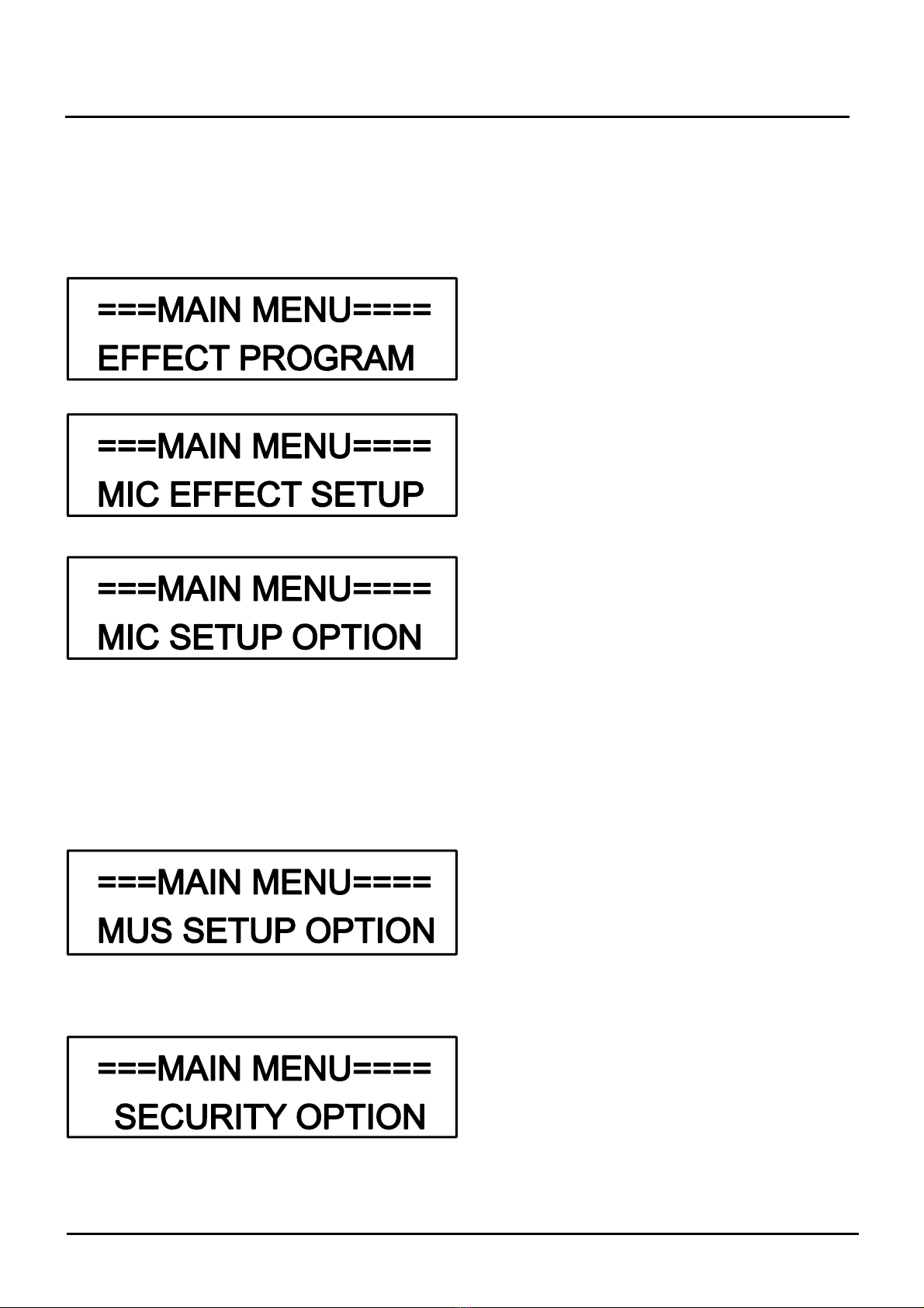
1. The system provides multi functional solutions. Press MAIN MENU and SUB-MENU. The button
MENU is used to enter into MAIN MENU or SUB-MENU, it is also used to confirm the current
parameters. Menu button (“<-” & “->”) are used to operate different menu and all the options, the
parameter of increase & decrease button (“#” & “b”) are used to adjust current menu parameter.
Load a Effect
Store a Effect
Erase a Effect
Load Ini Effect
Store Ini Effect
(EFFECTMODEAND
PAR AMETER)
MIC N_GATE
MICINIVOL
MICMAXVOL
EFFINIVOL
EFFMAXVOL
EFFINIMODE
CNTINIVOL
CNTMAXVOL
REMOTESEL
REMOTEMODE
RS232 MODE
MUS N_GATE
BALANCE
MUSINIVOL
MUSMAXVOL
AUDIOINPUT
AVSWITCH
MUSICDELAY
(SAFECODESETUP)
Chart 12 (Main Menu Structure)

10
OPERATING INSTRUCTION
2. Press Confirm button to get in Sub-Menu from MENU. See chart 13 below. There are five Effect
functions to be set up on Sub-Menu Category, procedures as following:
Chart 13 (Effect Set Up MENU)
<Adjust effect program>
Press Menu button to get to Effect program
adjustment menu. LCD screen will show adjust
menu fail if the system do not load the effect view.
Otherwise, get in series number of effect memory in
current loaded programme, use the parametric
increase & decrease button “#” & “b” to select an
effect ,then press the Confirm button to get to the
next menu.
Memorized
Mode No Memorized Mode
Series Number Load Programme
LCD screen will show you to press Confirm
button to invoke effect programme then get
to the next step after pressing the menu button.
LCD screen will show loading after, auto
back to Main Menu, the EFFECT program set up
is finished.

11
OPERATING INSTRUCTION
<Load effect programme>
Press Menu button to get in to the Effect program
Menu “Store a Effect” view.
UseParametricbutton“#”&“b”toselectaposition
to Load Effect program LCD screen will show “?” on
bottom right corner if the current series number has
loaded program before, then press the confirm button to
next interface.
Programme
series number
Setupthenameofmemoryprogram,us
parametric button (“#” & “b”) to adjust current
character size of cursor indication, use parametric
moving button (“<-” & “->”) to change the location
of cursor indication character,10 character can be
saved on every loaded memory.
Cursor indication
Edit programme name
Press Confirm button (Menu) to save the effect
Program and back to Main menu.

12
OPERATING INSTRUCTION
<Delete Effect Programme>
Press Menu button to get in Erased Menu of Effect
Program. The LCD screen will show that erasing failed.
Other wise, get in series number select of erasing
program, in current memory program. Use Parametric
button (“#” & “b”) to select a Effect to be Erased, then
press Confirm button to step next interface.
Stored
Program No Stored program
Programme The name of
Series number loaded programme
LCD screen shows to press Confirm (Menu) button
to erase the Effect, press “Menu” button to get in to next
interface.
One LCD Screen shows “Erasing” procedure is
finished, it will auto back to the “Main” Menu.

13
OPERATING INSTRUCTION
<Invoke Start Effect Programme>
Press Menu button to get in to initial Effect program
loaded menu, Press Menu button to step in to next
interface.
The system screen will show initial loaded Effect
program. Press Menu button then step in to neat
interface.
LCD screen shows Press menu button to load
initial loaded Effect program, then press menu to step in
to next interface.
Once LCD Screen shows procedures is finished, it
will auto back to the “Main” Menu.
<Storage Initial Effect Program>
Press Menu button to get in Storage menu of initial
Effect, press Menu button again to get to next interface.
The system screen show the initial Effect Program, then
press the Menu button to next interface.
LCD screen shows that Press menu button to store
initial effect program, then get to next interface.
Auto back to main menu after LCD screen shows
storing the program currently, wait till the
loading is finished.

14
OPERATING INSTRUCTION
<Effect Mode & Parameter>
Press Menu button to get in to Effect program Set Up
menu.
Use “#” & “b” knob to set up Effect mode, provide
total 14 Groups Mix and 4 Groups Echo Effect
combination crossover mode. Echo and Mix Effect can
not be chosed at the same time when changing Effect.
Press“<-”&“->”buttonmoretheparametricmenu,
follow current selective effect mode, it provide Mix
Delay, Mix High Pass Mix Low Pass Echo High Pass,
Echo Low Pass etc. Parameter “Set Up” interface.

15
OPERATING INSTRUCTION
3. Select MIC SETUP OPTION in the main menu interface press “Menu” button to get in Submenu.
See Chart 14 below, use “<-” & “->” button to select different parameter option.
Chart 14 (Mic Setup Menu)
MIC Noise Gate Setup: MIC N-Gate Threshold in the menu, Setup range is -90dB~-24dB. This
parameter can reduce the MIC Noise Efficiency. The greater the threshold,
more Noise components could be reduced. It includes some small signals
(performer sings softly.) Default Value is -66dB.
MIC volume Pre-install: To set up MIC part preinstall volume. This parametric set up is mainly to
support karaoke volume project. When the system switch is on, the MIC
volume always stays at the pro-installed Value. If the MIC volume required
to at minimum when switch on every time, set the value at -26dB.
MIC Volume Limitation: Set up MIC volume in the menu, this parameter is to maximum of MIC set
up limit. For example: Parameter set up in -10dB,so MIC volume set up
limit is max -10dB,when user uses MIC volume knob or remote set up MIC
volume, max output is -10dB,the parameter mainly protect the amplifier
and speakers when output is in a certain range limit.
Effect Volume Pre-install: To set up the Initial Preinstall Volume in menu this parameter set up is
mainly provides karaoke project when the system switch to Echo
Volume on a Pre-install rang.

16
OPERATING INSTRUCTION
Effect Volume Limitation: Set up Effect Volume allowance value in menu, this parameter is to
control center volume set up limit. For example: parameter set up -6dB
center volume limit is -6dB.The parameter range is -30dB~0dB.The
reason to set up Volume Limitation is to protect speakers output level.
Centre Volume Pre-install: To set up center output Initial Volume output power on condition. This
parameter setup is mainly to support Karaoke project. When power is
on, Centre Volume is always loading on Preload value. To set up to
minimum center volume when starts, select -30dB.
CENTER Volume Limitation: To set up center volume allowance value in the menu, this parameter
is to adjust to maximum Center Volume. For example: when the
parameter is -20dB,The limit of center adjustment is -20dB.When
user use center volume knob or remote to adjust the center volume,
maximum output is -20dB and the parameter range is -30dB~0dB.
This step is to protect amplifier & speaker in certain output range.

17
OPERATING INSTRUCTION
Set up Power on Effect Mode: This function is to set up power on Effect made when the parameter has
set up on initial mode in the system to invoke Pre-install parameter. The
system will invoke effect parameter previously when the parameter set up
is off.
(MIC EFFECT SETUP)
(STORE INITIAL EFFECT)
ON OFF
Remote Input Select Set up: This function is mainly to set up input terminal of remote, this system allows
user using wireless remote to set up parameter when the parameter has set
up in “IrDA” when the parameter shows “line” ,the system allow user using
wireless remote terminal to set up parameter.
Remote Invoke Effect Setup: This function is to set up invoke mode of remote when the parameter set
up in “press” ,user can use remote control to set up 7 kinds of Pre-install
Effect. User can use remote control to set up the effect base on 10 kinds of
user defined mode.

18
OPERATING INSTRUCTION
4. Select MUS SETUP OPTION in main menu, press “Menu” button to get in Sub-menu. See Chart
15 below, then use “<-” & “->” button to select different parameter option.
Chart 15 (Music Setup Menu)
Music Noise Gate set up: To set up music N-gate Threshold in the menu, set up range is -90dB~
-24dB.This parameter can reduce the exiguous noise effectively.
Gaining threshold range can reduce more noise component, including
small signals. Default Value is -66dB.
Output Balance set up: Press parameter (“#” & “b”) button to set up till LCD screen shows “R0%”,
it means right channel output in minimum. Set up till LCD show
“LR100%” means left & right channel output is the same.
Music Volume Preinstall: To set up Pre-install in volume in menu. This parameter set up is mainly
to support karaoke project. When the machine power is on, the music
volume is always on Pre-installed volume. To set up Pre-installed
volume to minimum when power is on, just to select -30dB.

19
OPERATING INSTRUCTION
Music Volume Limitation: To set up music Volume allowance value in the menu. This Parameter is to
maximum limitation, for example when the parameter set up in -10dB, music
volume allowance value set up to -10dB, use knob or remote to set up,
maximum output volume is -10dB, the parameter range is -30dB, this
parameter limitation, set up is to protect the amplifier and speaker on certain
range of output.
Music Signal Input Select: Setting up Music Signal Input in the menu, there are 6 options: DVD, BGM, B6,
B9, B12, B15, the last 4 options (B6, B9, B12, B15) are priority for auto-switch
selection of BGM, refer below steps connect BGM signal to the DGM jack of
audio input, connect the KARAOKE signal to DVD.
Set up BGM Auto Convert Priority mode, select BGM input first. Any groups
audio play, the system auto convert to this group. As left chart, the system will
auto convert to BGM audio based on pre-installed BGM convert timing when
vocal stops. For example: As left chart DVD audio, when the DVD audio is off,
the system will auto convert to BGM if No audio signal after six seconds, and B9,
B12, B15 will auto convert after 9, 12, 15 seconds.
Fixed Audio Mode set up: first to select any group and connect to performer
audio. For example: set up Homologous Input Channel in the menu, as left
chart, on DVD audio this moment, the system has connected input audio from
DVD spur track, the audio always stays on pro-installed Input branch track.
DVD BGM
L
R
DVD BGM
BGM Function Audio
Connection
DVD
L
R
DVD
Regular Audio
Connection
Table of contents


