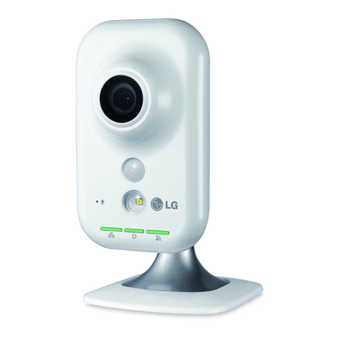
Digilant SA02-04 User manual

Standalone Surveillance Camera
Installation Manual

WARNING
•This Camera is installed at owners own risk. The owner of this camera
should check all state and federal privacy laws, if existing, prior to using and
operating this device.
•This Camera and optional battery charger must only be operated with
genuine battery packs, sourced and supplied by Moreton Bay Systems The
substitution and consequent use of any other battery pack will not only void
the warranty but could cause serious injury if the battery pack ignites or
explodes.
•Moreton Bay Systems (MBS) shall not be held liable of any misuse or
unlawful operation of this product.
NOTICE
No part of this material may be reproduced or duplicated in any form or by any
means without the written permission of Moreton Bay Systems. Moreton Bay
Systems reserves the right to make changes to this material without notice.
Moreton Bay Systems does not assume any liability of any kind arising out of
inaccuracies contained in this material or due to its application.
The product is designed to detect moving objects and capture images. It can also be
connected to a third party alarm system. Being only a part of a security system,
Moreton Bay Systems is not responsible for any damages or other consequences
resulting from an intrusion.
All other product names mentioned herein are trademarks and/or registered
trademarks of their respective companies.
© MORETON BAY SYSTEMS 2009, All rights reserved.

SA02-04
I
NSTALLATION
M
ANUAL V
1.1.2
(
APRIL
2009) 1
T
ABLE OF
C
ONTENTS
LISTOF FIGURES 2
INTRODUCTION 3
O
VERVIEW
3
S
PECIFICATIONS
4
S
URVEILLANCE
C
AMERA
5
O
PTIONAL
A
CCESSORIES
5
C
IRCUIT
B
OARD
L
AYOUT
6
INSTALLATION 7
G
ETTING
S
TARTED
7
C
HOOSING
A
C
AMERA
L
OCATION
11
E
XTERNAL
T
RIGGER
13
CAMERA OPERATION 14
C
APTURED
I
MAGES
A
VAILABLE
15
C
APTURING AN
I
NSTANT
I
MAGE
15
O
THER
LED
P
ATTERNS
16
C
HOOSING
A
N
I
MAGE
S
EQUENCE
16
M
EMORY
C
ARD
17
M
EMORY
C
ARD
C
APACITY
17
M
EMORY
C
ARD
F
ORMATTING
18
M
EMORY
C
ARD
C
ONTENTS
19
B
ATTERY
O
PERATION
21
B
ATTERY
P
OWERED
C
AMERA AND
R
EMOTE
C
ONTROL
22
R
ECHARGING
T
HE
B
ATTERY
22
B
ATTERY
L
IFE
23
I
NSTALLING THE
B
ATTERY
24
PC
S
OFTWARE
25
TROUBLE SHOOTING 26
APPENDIX A:SECURITY SYSTEM INSTALLATION 30
APPENDIX B: LED PATTERNS 33
DECLARATION OF CONFORMITY 35
DISPOSAL OF ELECTRONIC PRODUCTS IN EU 35

SA02-04
I
NSTALLATION
M
ANUAL V
1.1.2
(
APRIL
2009) 2
L
IST OF FIGURES
Figure 1 - Camera Components............................................................................................................... 5
Figure 2 - Optional Accessories .............................................................................................................. 5
Figure 3 - Circuit Board Layout .............................................................................................................. 6
Figure 4 - Formatting the memory card..................................................................................................18
Figure 5 - Rapid Battery Charger ...........................................................................................................22
Figure 6 - Battery Installation................................................................................................................24
Figure 7 – Camera Setup Software.........................................................................................................25
Figure 9 – Security System Wiring Examples.........................................................................................30
Figure 10 - Armed and External Trigger Wiring.....................................................................................32

SA02-04
I
NSTALLATION
M
ANUAL V
1.1.2
(
APRIL
2009) 3
I
NTRODUCTION
OVERVIEW
The Digilant Standalone Camera is a low power digital camera that captures images
when motion is detected within its field of view. The images are stored on a removable
memory card for easy viewing on a computer.
For fast and easy setup, the camera comes pre-configured with all the settings
required for standalone surveillance operation and only needs the date and time to
be set. This document outlines the steps involved with installing and using the camera
based on these settings.
Please read this entire manual before using the camera in order to get the most
out of its features and functions.
A complete set of Installation and ser Manuals can be found on the Camera Setup
CD in the ‘User Manuals’ folder. These documents are also copied into an ‘All
Programs/Digilant’ folder in the Start Menu during Camera Setup soft are installation

SA02-04
I
NSTALLATION
M
ANUAL V
1.1.2
(
APRIL
2009) 4
SPECIFICATIONS
Camera nit
Image Type Colour or B&W, JPEG compressed
VGA (640x480pixels), QVGA (320x240)
Camera Lens Standard: 3.7mm, 54˚ horizontal, 39˚ vertical
Image Sensor Sensitivity Colour: 3.8 V/Lux-sec, B&W: 4.9 V/Lux-sec
Motion Sensor Type: PIR
Range: 0-5 m (16’) (Typical), 0-8 m (26’) (Maximum)
Field Of View: 100˚ horizontal, 82˚ vertical
Memory Card MMC™ Card (v4.2) or SD™ Card (v1.1), FAT16 file format
Storage Capacity 2GB Memory Card: VGA: 32,000 images, QVGA: 65,000
images
External Power Supply 9VDC to 13.8V DC, 250 mA (Plug tip polarity + or -)
InternalBattery Capacity High Capacity (HC) – Lithium Ion, 3.7V 3000mAh
Photo-relay Specifications 60VDC, 400mA
Power Consumption Standby: 1.9 mA
Running: 100 mA
Charging: 200 mA
Case Dimensions 116 x 67 x 55 mm (4.6” x 2.6” x 2.2”)
Weight 172g (6 oz), including battery
Operating Temperature -20˚C to +60˚C (-4˚ F to +140˚ F)
PC Software Requirements Windows 2000 (SP4),Windows XP (SP2),Windows Vista
Remote Control
Transmission type Infrared
Operating distance 0 – 5m (typical)
Battery 12V Alkaline, type 23A
Dimensions 57 x 37 x 16 mm
Weight 26 g (Including battery)
Operating Temperature 0˚C to 50˚C

SA02-04
I
NSTALLATION
M
ANUAL V
1.1.2
(
APRIL
2009) 5
SURVEILLANCE CAMERA
Front Case Circuit Board Rear Case
F
IGURE
1
-
C
AMERA
C
OMPONENTS
OPTIONAL ACCESSORIES
USB Memory Card Reader
Memory Card
Remote Control
Software CD
Back up Battery
High Capacity Battery
Rapid Battery Charger
DC Power Pack
F
IGURE
2
-
O
PTIONAL
A
CCESSORIES
*Accessories may vary from those pictured here
4. Flush mounting
screw holes
2. Wiring inlet
3. Side clips
5. Bevelled edge
mounting screw
1. Battery
compartment

SA02-04
I
NSTALLATION
M
ANUAL V
1.1.2
(
APRIL
2009) 6
CIRCUIT BOARD LAYOUT
F
IGURE
3
-
C
IRCUIT
B
OARD
L
AYOUT
Legend
1. 9V DC Power Socket
2. Tamper/Auto-arm Switch
3. Power Switch: UP = ON, DOWN = OFF
4. Infrared Receiver
5. Motion Sensor
6. Memory Card Socket
7. Status LED
8. Image Sensor and Lens
9. Screw Terminal Block
10. Optional Siren/Strobe module
6
8
5
4
2
7
3
8
7
6
5
4
3
2
1
12V
0V
Power
Relay
N.C.
Trig
Armed
Tamper
N.C.
1
9
DC Power Plug
ON
On
Off
Power
10

SA02-04
I
NSTALLATION
M
ANUAL V
1.1.2
(
APRIL
2009) 7
INSTALLATION
GETTING STARTED
Step 1 – Recharge the battery
For more information on battery operation, refer to page 17.
Step 2 – Install Camera Setup Software
Insert CD Follow screen prompts to
install software
Insert memory card reader
3
2
1
4
Start program using the desktop
short cut
Wait up to ~34 hours**
Apply DC power via jack
or terminal strip
2
3
0V,12Vdc
9Vdc
or
1
Connect battery
Plug-in connector
** The camera itself only
trickle charges the battery
The optional rapid battery
charger however will reduce
the charging time to ~ 5
hours to enable 24/7
surveillance using battery
swapping.

SA02-04
I
NSTALLATION
M
ANUAL V
1.1.2
(
APRIL
2009) 8
Step 3 – Obtain current camera settings
After removing the card from the camera it ill contain a file ith settings in it. The
format of the contents of this file is critical to the camera operating correctly and should
only be changed using Camera Setup soft are.
If the settings file has been modified via a third party editor and the camera does not
function properly, delete settings.txt from the card and repeat step 5. A ne file
containing the current settings ill automatically be generated by the camera.
Step 4 – Set Camera Date and Time
Insert
Remove
Power
switch ON
(UP)
Wait up to 30s until 1
green blink per motion
trigger
2
4
3
1
Insert card in reader
Start Camera Setup software
and select ‘Configuration’
(Default) then click on
‘Continue’
Step 3 - Obtain current camera settings
Ensure memory card contains
current camera settings
1
2
3

SA02-04
I
NSTALLATION
M
ANUAL V
1.1.2
(
APRIL
2009) 9
Date and time are maintained by the camera when switched OFF via the power
switch.
Step 5 – Capture and view a test image
Select “SETTINGS.TXT” on
card then click on ‘Open’
Locate memory
Select ‘Computer Time’
Save changes to the memory
card
Enter camera location
6
4
7
5
8
Insert card in camera
9
In order to preserve date and time
accuracy, the card should be inserted
into camera ith camera po er ON
immediately after the settings changes
are saved to card.
This description ill appear in
the text overlay at the bottom
of all images captured by the
camera
Sets date and time for the time
stamp that is in text overlay at
the bottom of all images
captured by the camera
Microsoft Windo s often
calls memory card drives
“Removable Disk”
Status LED flashes orange for 2 seconds
1
Press middle (blue) button
Test image

SA02-04
I
NSTALLATION
M
ANUAL V
1.1.2
(
APRIL
2009) 10
Test images are stored on the memory card in a folder named DCIM and under that
are directories named xxxDIR00 where xxx is a number from 100 - 999. The folder
with the largest number contains the most recent images.
With the test image(s) displayed in the Camera Setup Image Viewer, reread Choosing
A Camera Location (page 11) and ensure that the camera is installed in the most ideal
location.
Most recent
folder
Test
images

SA02-04
I
NSTALLATION
M
ANUAL V
1.1.2
(
APRIL
2009) 11
CHOOSING A CAMERA LOCATION
The camera utilises still-image digital photography technology. As with any other
camera, consideration should be given to the desired image subject matter with
respect to light conditions, target person’s movement, and distance. Similarly, thought
should be given to the motion sensor operation to ensure that the target person is still
within the camera’s field of view when the image is captured.
Prior to installing a camera consider the following factors:
1. Direction and amount of available light
To achieve the highest quality images,
ensure that the area being monitored
is well lit and that any ambient light
(eg from a window) is behind the
camera. Having a light source in front
of the camera will result in the image
having extra white in it as well as
detail being lost in darker, unlit areas.
2. Direction of movement
If movement is across the field of view,
say, left to right, then some image
blurring will occur in low light
conditions. Also, the motion sensor is
least sensitive for movement directly
towards the camera.
If possible, it is best to position the
camera such that target person walks at
a slight angle to its field of view.
Movement
Behind camera
In front of
camera
Light

SA02-04
I
NSTALLATION
M
ANUAL V
1.1.2
(
APRIL
2009) 12
5m (typical), 8m (maximum)
2m
4.5m (typical
)
,
7.7
m
(
maximum)
3. Target location
The camera takes highest quality
images when the target person is still
or paused. Consider the layout of the
room and point the camera where the
target person is most likely pause or
stand still eg at a counter with a cash
register or in a door way or in front of a
valuable item.
4. Distance to target
For detailed facial recognition, the
camera’s optimal distance to target is
up to 5m. If the target person is too
far away from the camera then some
resolution detail may be lost.
However, details such as colour, hair
style, and clothing style will still be
identifiable.
The optimum height for a camera to
be installed is 2m.
5. Angle of vision
The motion sensor detects a larger
angle of vision than shown in the
camera images. To prevent false
triggers care should be taken to
point the camera at a wall or floor
or large object. Avoid having an
open door way or window or high
traffic area 15
o
either side or 20
o
above or below a test image.
Person
moving
Person
moving
Person
pauses at
valuable
object
70
o
15
o
15
o
Field of view:
Motion sensor 100
o
horizontal, 82
o
vertical
Camera 54
o
horizontal, 39
o
vertical

SA02-04
I
NSTALLATION
M
ANUAL V
1.1.2
(
APRIL
2009) 13
6. Temperature variation
Motion detection works by monitoring
for temperature differences caused by
a target person’s movement and the
background temperature. Avoid
pointing the camera at sources of
temperature changes such as stoves,
kettles, air conditioning, heating vents
and pets.
E
XTERNAL
T
RIGGER
The external trigger input is an alternative means of triggering the camera other than
the motion sensor. It can be connected to doors, windows, cash registers etc. The
camera can monitor both the external trigger and internal motion sensor
simultaneously or the motion sensor can be disabled leaving the external trigger to
start Event-Triggered image capture sequences.
By default, the external trigger is activated when it connects to 0V. This operation can
be changed to trigger on an open circuit using the Camera Setup software.
As is the case with the motion sensor, the camera must be armed before the external
trigger will start an Event-Triggered image capture sequence.
For external trigger wiring instructions, refer to Appendix A, Figure 9.
Temperatu
re variation

SA02-04
I
NSTALLATION
M
ANUAL V
1.1.2
(
APRIL
2009) 14
1 sec
Red
Motion sensor activation when armed
CAMERA
OPERATION
The camera will only capture images when
it is armed.
Arming and disarming the camera can be done
either by using the remote control, or by using
external arm input wiring, or via the camera
software’s scheduler feature.
When the camera is not armed, the status LED
will flash green for one second each time
motion is detected.
Arming the Camera
When the camera is arming the status LED will
rapidly flash red for 5 seconds.
Upon arming, the camera will capture and write an
“arm” image to the memory card. It will also keep
the motion sensor disarmed for 30 seconds to
enable the user to move out of range.
Once the camera is armed, the LED will flash red
for one second each time motion is detected.
Disarming the Camera
When the camera is being disarmed the status
LED will rapidly flash green for 5 seconds, or
until it is safe for the memory card to be removed.
Upon disarming, the camera will capture and write
a “disarm” image to the memory card.
1 sec
G
reen
5 sec
System
Armed
30 sec
Arming
the camera
R
R
R
R
R
R
R
> 5 sec
System
Disarmed
Disarming the camera
G
G
G
G
G
G
G
Arm
(Red)
Capture Image (Blue)
Disarm (Black)
Motion sensor activation when
disarmed

SA02-04
I
NSTALLATION
M
ANUAL V
1.1.2
(
APRIL
2009) 15
A memory card can be corrupted if it is removed
hilst the camera is riting images to it. Only
remove the memory card after the status LED stops
its rapid green flashing. Do not remove the card
hile the camera is armed.
If a card is corrupted because of early removal then it can be reformatted and reused.
Refer to Memory Card Formatting (page 18) for more information.
C
APTURED
I
MAGES
A
VAILABLE
After disarming, if the camera has captured any
images whilst armed then it will indicate that
images are available by flashing orange in 1
second pulses. The camera will also show the
same orange flash sequence if the card is not
inserted.
C
APTURING AN
I
NSTANT
I
MAGE
To force the camera to capture an image independent of the motion sensor, point the
remote control at the camera unit and press the middle (Blue) button.
Status LED
1
P
ress
m
iddle (blue) button
Test image
Disarmed
Arming,
Disarming,
or Armed
Card Removal
2 sec
Orange
1 sec
Captured images are
available on memory card, or
card not inserted.
O
O
O
O

SA02-04
I
NSTALLATION
M
ANUAL V
1.1.2
(
APRIL
2009) 16
O
THER
LED
P
ATTERNS
Date and Time not set
Fast orange flashing for 3 seconds. This
sequence occurs on power up after the system has loaded.
System is loading
Constant orange until loading has completed.
Do not remove memory card while the system is
loading.
Critical Error
Constant red LED. Remains active until error is
fixed. Turn power off, then on again. If LED stays
red again, contact your distributor
C
HOOSING
A
N
I
MAGE
S
EQUENCE
The choice of image capture sequence could mean the difference between catching
someone in the act and catching his or her shadow. The camera’s default settings are
designed for a single image per capture sequence per motion trigger. This maximizes
the rate of image capture to card whilst keeping the time lag between sequences to a
minimum. However, this may not always be the preferred installation.
For optimum use of the camera’s many advanced features the user is strongly
recommended to read the ‘Choosing An Image Sequence’ section of the camera’s user
manual. Experimenting with various features such as capturing images prior to
motion detection (pre-trigger), capturing multiple images per motion trigger (event-
trigger), and capturing images based on a timer (time-lapse) should be considered.
On until safe to remove
Orange
On until error is fixed
Red
3 sec
O
O
O
O
O
O
O

SA02-04
I
NSTALLATION
M
ANUAL V
1.1.2
(
APRIL
2009) 17
MEMORY CARD
The camera will accept both MMC™ and SD™
memory cards ranging from 32MB to 2GB with the
FAT16 file format. SDHC
TM
cards are not supported.
When the images have been copied from the memory card to the computer, remember
to make room for new images by deleting the old ones from the card before inserting it
back into the camera.
M
EMORY
C
ARD
C
APACITY
The number of images that a memory card can store is dependent upon a number of
factors:
oSize of image resolution being captured – high or medium
oWhether the text overlay feature is enabled or disabled
oThe JPEG compression performance varies depending upon image content. This
variation results in varying file sizes.
The table below lists estimate card capacity values based on assumption that average
image size is 40kB high and 15kB medium resolution colour images:
Card Capacity High Resolution Medium Resolution
32 MB 800 2200
64 MB 1600 4300
128 MB 3200 8100
256 MB 6500 16300
512 MB 13100 32700
1 GB 22000 65000
2 GB 32700 65000
T
ABLE
1
–
M
EMORY
C
ARD
C
APACITY
SD
TM
/
MMC
TM
32MB –
2GB
SDHC
TM

SA02-04
I
NSTALLATION
M
ANUAL V
1.1.2
(
APRIL
2009) 18
M
EMORY
C
ARD
F
ORMATTING
In the rare case that the memory card has been corrupted, it may be necessary to
reformat the card. The memory card must be formatted with FAT16 file system.
F
IGURE
4
-
F
ORMATTING THE MEMORY CARD
To format the memory card with FAT16 file system:
1. Insert the memory card into the USB reader and plug the reader into a USB port
on the computer.
2. Open My Computer, right click the Removable Disk containing the memory card
and click Format… This will bring up the Format Removable Disk window in
Figure 4.
3. Select FAT (not FAT32) in the File System box and click Start.
Must be FAT (Not FAT32)
Table of contents
