Before Lock Installation
Door Preparation
Strike Plate Installation
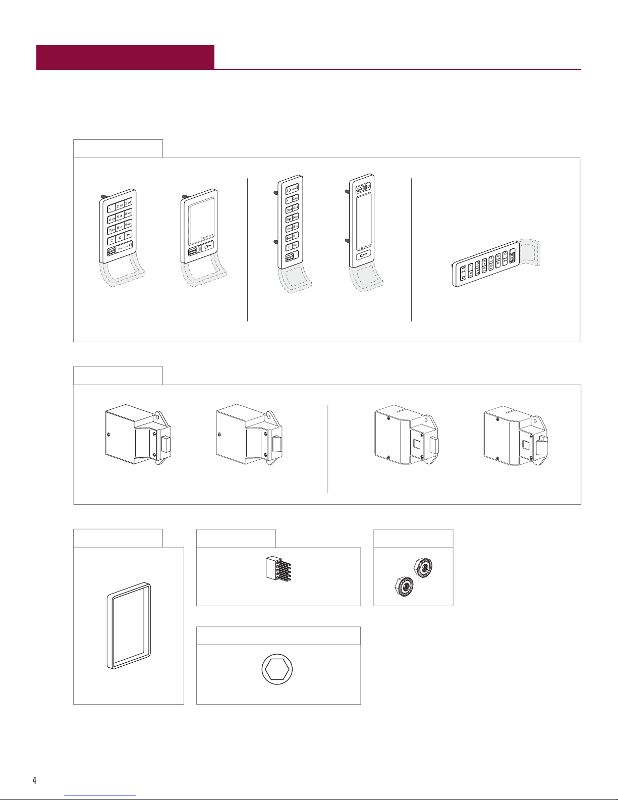
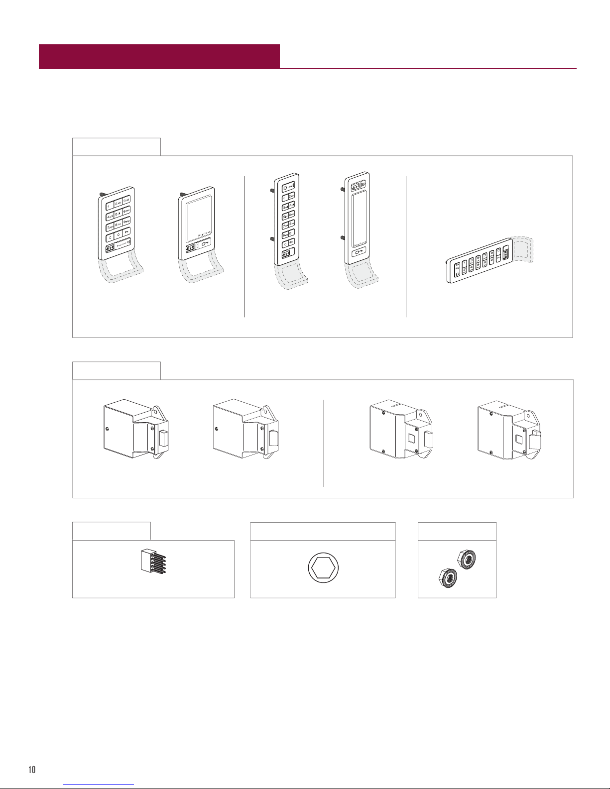
Required Components
Installation
Door Mounting Holes Drill Instructions and Templates
Drill Instructions
Template for Standard & Vertical Body
Template for Horizontal Body
Routing Instructions and Template
Routing Instructions
Routing Template for Standard Body
Routing Template for Horizontal Body
Routing Template for Vertical Body
Metal Door Preparation
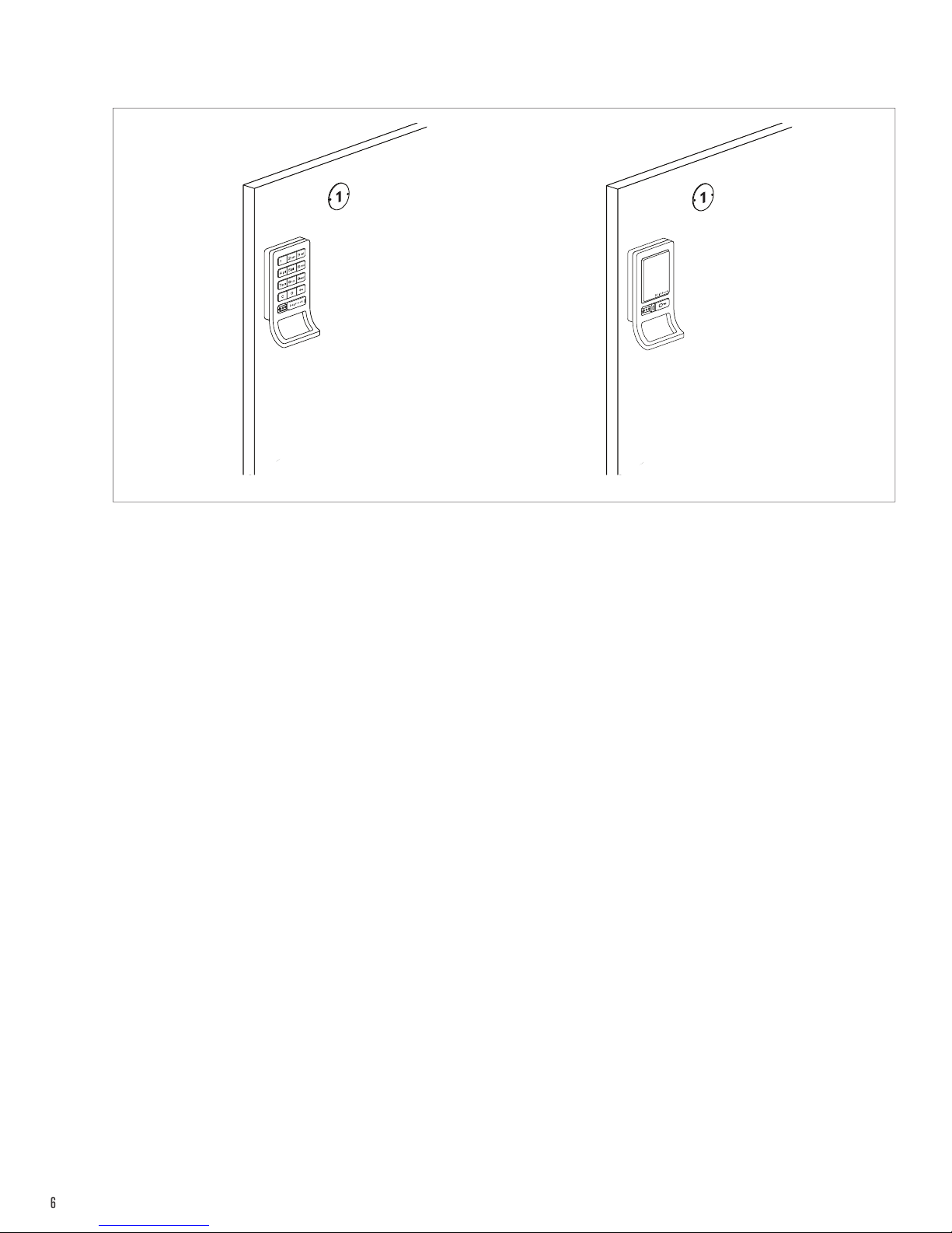
Compatibility Guide
Removal of 3-hole Lock Plug
Removal of Padlock Hasp
Recess Mount Installation
For door thickness measuring between .370” - .850” (9.4mm - 21.6mm)
For door thickness measuring between .850” - 2.368” (21.6mm - 60.1mm)
Required Components
Required Components
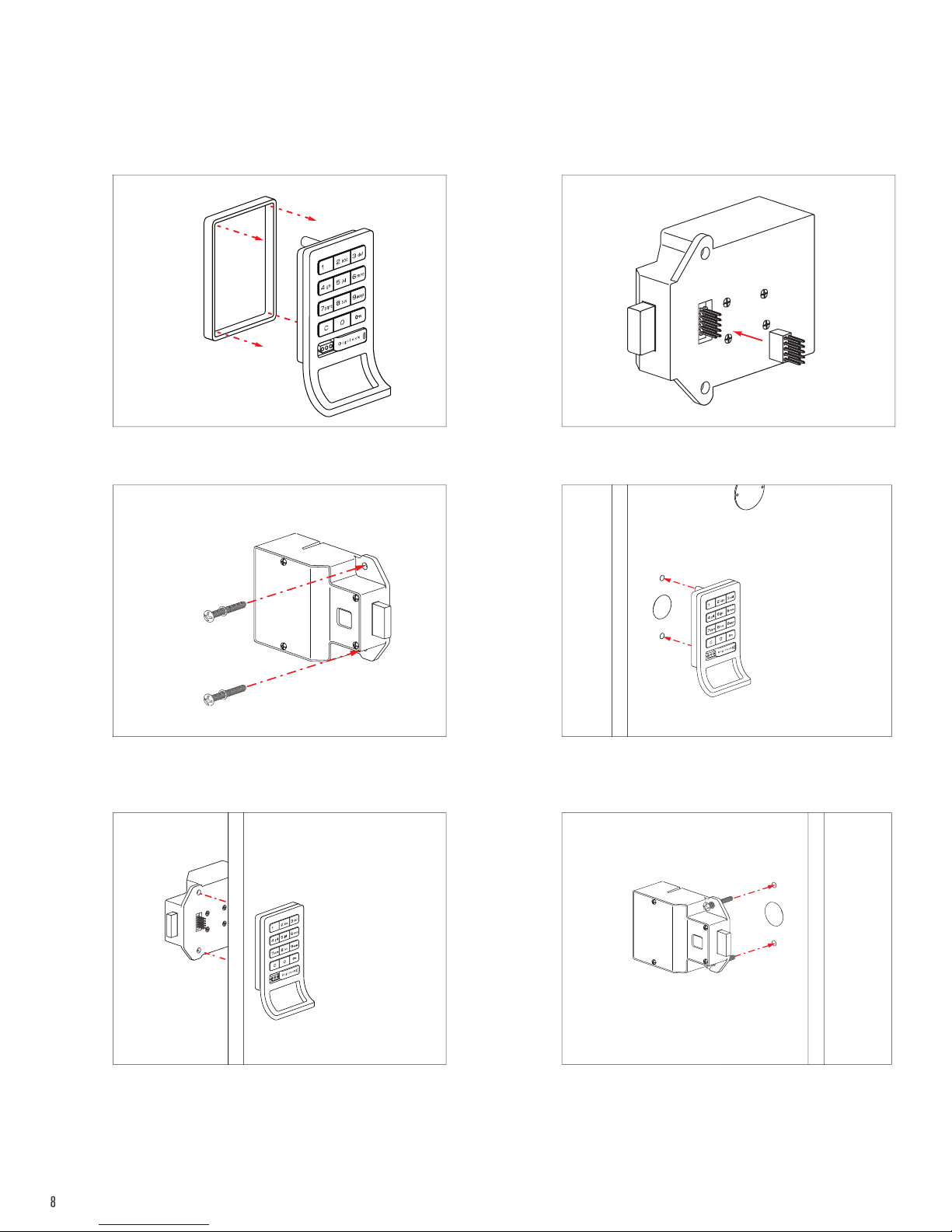
Installation
Installation
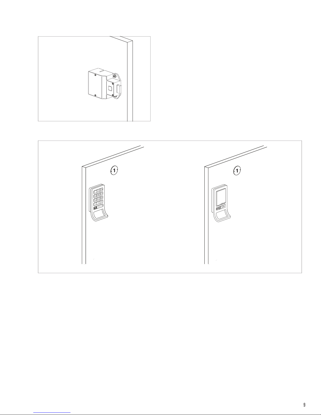
Surface Mount Installation
For door thickness measuring between .01” - .480” (0.01mm - 12mm)
For door thickness measuring between .480” - 1.998” (12.2mm -50.7mm)
Required Components
Required Components
Installation
Installation