Fortress Building Products Al 13 HOME PURE VIEW User manual

Al13 HOMETM WITH PURE VIEW® FULL GLASS PANEL INFILL INSTALLATION
Al13 HOMETM ALUMINUM RAILING
WITH PURE VIEW®FULL GLASS PANEL INFILL
INSTALLATION INSTRUCTIONS
HOMETM
Al13
Pure View®Full Glass Panel

2
Al13 HOMETM WITH PURE VIEW® FULL GLASS PANEL INFILL INSTALLATION
English
Introducon.........................................................................3
LevelBracket........................................................................4
AngledBracket...................................................................27
Care&Maintenance/Warranty..........................................35
TABLE OF CONTENTS

Al13 HOMETM WITH PURE VIEW® FULL GLASS PANEL INFILL INSTALLATION
3
Al13 HOMETM WITH PURE VIEW® FULL GLASS PANEL INFILL INSTALLATION
INTRODUCTION
READ INSTRUCTIONS COMPLETELY BEFORE
STARTING INSTALLATION
It is the responsibility of the installer to meet all code and
safety requirements, and to obtain all required building
permits.Thedeckandrailinginstallershoulddetermine
andimplementappropriateinstallaontechniquesfor
eachinstallaonsituaon.FortressRailingProductsandits
distributors shall not be held liable for improper or unsafe
installaons.
FortressPostsmustalwaysbesecuredtothedeck
framingandshouldneverbeaachedtoonlythedeck
boards.
PureViewI-SupportisrequiredforCanadian
CodeCompliance.
Note
WhencungFortressrailing,itisveryimportantto
completethefollowingatcutpoints:
• Removeallmetalshavingsfromthecutarea.
• Fileanysharpedgeslebycung.Thoroughlywipeand
removeanylings,grime,ordirtfromtherailing.
• ApplytwocoatsofFortresszincbasedtouch-uppaintto
thecutarea.Iftouchupisatrailends,allowpainttodry
beforeconnecngbrackettopost.
• Be sure to remove any metal shavings from the surface of
deck,pao,orbalconytopreventstainsonthedeck
surface.
Torx Safety Tips
• Alwaysusethelowestspeedsengondrill.
• Toreducechanceofbitbreakage,startghteningwithdrill
onlowtorquesengandworkupunlscrewissecured.
Tip: Pre-drill holes with 3/16” [5mm] drill bit.

4
Al13 HOMETM WITH PURE VIEW® FULL GLASS PANEL INFILL INSTALLATION
Required Tools
Goggles
Drill
Tape
Measurer
Level
Tool
Speed
Square
Touch-Up
Paint
Miter
Saw
T-25
Driver Bit
#2Phillips
Head Bit
Bit
Extender
5/16”[8mm]
Nut Driver Bit
DrillBits:1/16”,
3/16”,3/8”,5/8”[2mm,
5mm,10mm,16mm]
Pure View: Al13 HOME Full Glass Panel Installaon Opons
Socket
Set
Pencil
Rubber
Mallet
Hex
Wrench
Crescent
Wrench
Socket
Wrench
PostCap
StraightBracketCup
Al13HOMEPostwithPostBaseCover
StraightBracketCap
Spring
Punch
Safety
Gloves
Liquid
Soap
Ratchet
Straps
2”[51mm]or3”[76mm]ProudPost
PureView:Al13 HOMEFullGlassPanel68-1/2”[1740mm]
RoundAccentTopRail
FlatAccentTopRail
PureViewFullGlass
Al13HOMEVercalCable/
PureViewI-Support
File
Al13 HOMETM WITH PURE VIEW® FULL GLASS PANEL INFILL INSTALLATION
5
Al13 HOMETM WITH PURE VIEW® FULL GLASS PANEL INFILL INSTALLATION
2”[51mm]OverThePost(OTP)
FlatATRLine
Splice
RoundATRLine
Splice RoundAccentTopRail
FlatAccentTopRail
StraightBracketCup
StraightBracketCup
PureView:Al13 HOMEFullGlassPanel68-1/2”[1740mm]
Al13HOMEPostwithPostBaseCover
PureViewFullGlass
Al13HOMEVercalCable/
PureViewI-Support
2”[51mm]or3”[76mm]ProudPostConguraons
*Installedheightsincludea3-1/2”[89mm]forthe32-1/2”[826mm]panel&2”[51mm]forthe
40”[1016mm] panel spacebetweendecksurfaceandboomedgeofboomrail.
Al13 HOME
Panel Height
40”[1016mm]
Rail Panel
42”[1067mm]
InstalledPanelHeight
45-1/2”[1156mm]
RequiredPost
32-1/2”[826mm] 39-1/2”[1003mm]36”[914mm]
2”[51mm]OverThePost(OTP)Conguraons
Al13 HOME
Panel Height
40”[1016mm]
Rail Panel
42”[1067mm]
InstalledPanelHeight
42”[1067mm]
RequiredPost
32-1/2”[826mm] 36”[914mm]36”[914mm]
*Installedheightsincludea3-1/2”[89mm]forthe32-1/2”[825.5mm]panel&2”[51mm]for
the40”[1016mm] panel spacebetweendecksurfaceandboomedgeofboomrail.

6
Al13 HOMETM WITH PURE VIEW® FULL GLASS PANEL INFILL INSTALLATION
FullGlassPanelSizeChart
12.25”
[838mmx311mm]
18.25”
[838mmx464mm]
24.25”
[838mmx616mm]
31.25”
[838mmx794mm]
36.25”
[838mmx921mm]
41.25”
[838mmx1048mm]
46.25”
[838mmx1175mm]
51.25”
[838mmx1302mm]
56.25”
[838mmx1429mm]
61.25”
[838mmx1556mm]
18”to23”
[457mmto584mm]
24”to29”
[610mmto584mm]
30”to35”
[762mmto889mm]
37”to42”
[940mmto1067mm]
42”to47”
[1067mmto1194mm]
47”to52”
[1194mmto1321mm]
52”to57”
[1321mmto1448mm]
57”to62”
[1448mmto1575mm]
62”to67”
[1575mmto1702mm]
67”to72”
[1702mmto1829mm]
15”to20”
[381mmx508mm]
21”to26”
[533mmx660mm]
27”to32”
[686mmx813mm]
34”to39”
[868mmx991mm]
39”to44”
[991mmx1118mm]
44”to49”
[1118mmx1245mm]
49”to54”
[1245mmx1372mm]
54”to59”
[1372mmx1499mm]
59”to64”
[1499mmx1626mm]
64”to69”
[1626mmx1753mm]
Glass Widths 3” [76mm] Post
O.C. Spacing
Between Post
Spacing
32 1/2” [825.5mm] & 40” [1016mm] Panels
17”to22”
[432mmto559mm]
2” [51mm] Post
O.C. Spacing
23”to28”
[584mmto711mm]
29”to34”
[736.5mmto863.5mm]
36”to41”
[914.5mmto1041.5mm]
41”to46”
[1041.5mmto1168.5mm]
46”to51”
[1168.5mmto1295.5mm]
51”to56”
[1295.4mmto1422.4mm]
56”to61”
[1422.4mmto1549.4mm]
61”to66”
[1549.4mmto1676.4mm]
66”to71”
[1676.4mmto1803.4mm]
Note:
321/2”[825.5mm]panelusesa31-1/2”[800mm]tallpieceofglass
anda40”[1016mm]panelusesa39”[990.5mm]tallpieceofglass.
POST MOUNTING
*IfusingFortressEvoluonFraming,contactFortressforinstrucons.
Note:
It’s recommended to install brackets into post before post mounng.
Reference page 9 for Bracket installaon steps.
Step 1: Install Wood Blocks
1. InstallWoodBlocklevelwithtopofjoist.Asshownin
Fig.1.

Al13 HOMETM WITH PURE VIEW® FULL GLASS PANEL INFILL INSTALLATION
7
Al13 HOMETM WITH PURE VIEW® FULL GLASS PANEL INFILL INSTALLATION
Step 3: Max Post Spacing
• 68-1/2”[1740mm]AL13HOMERailsmaximumpost
spacingis68-3/4”[1746mm].
Note:
• DO NOTexceedthemaximumpostspacing.
Fig. 1
#10x3-1/3”
[85mm]
(A)
(A)
Joist
Blocking
2. SecureWoodBlocktoblockingonallfoursideswith
#10X3-1/2”[89mm]deckscrews.
• WoodBlockmustbeconstructedwithtreateddimensional
lumberwithaminimumthicknessof1-1/2”[38mm].
Step 2: Posion Base Plate
1. Posiontheedgeofbaseplateaminimumof1/2”[13mm]
fromtheinsideedgeofrimjoist.AsshowninFig.2.
Fig. 2
1/2”[13mm]
1/2”
[13mm]

8
Al13 HOMETM WITH PURE VIEW® FULL GLASS PANEL INFILL INSTALLATION
Fig. 3
6’panelmaximumpostspacingis69-1/4”
[1759mm]
Step 4: Mount Posts
1. Markmounngholelocaonsandpre-drilla3/8”[10mm]
hole.
2. Insert3/8”x3-1/2”[10mmx89mm]HexHeadgalvanized
boltsthrough3/8”[10mm]galvanizedwasherandpost
baseplate.
Note:
• PostBasePlateholesMUSTbeposionedaminimum½”
[13mm]fromedgeofdeckboard.
• Useonly3/8”[10mm]HexHeadGalvanizedBolts.Lag
ScrewsshouldNOTbeused.Secureeachpostwithfour
bolts.
Fig. 4 Fig. 5
OTP and Proud Post: Max Post Spacing
• 8’ panel maximum post spacing is 93-7/8”.
• 6’ panel maximum post spacing is 69-7/8”.
Note: Do not exceed the maximum post spacing.
8’ Panel max post spacing 93-7/8”
6’ Panel max post spacing 69-7/8”
OTP and Proud Post: Measuring The Panel Opening Length
• Measure the distance of the panel opening.
• Measure from the back wall of the bracket to the back wall of the bracket on other post.
• Confirm that the measurements for the top brackets are the same as the bottom brackets.
Measure the panel opening
Not here
Measure from
back of bracket
Check measurement with top
3/12
Step 5: Check Mounted Posts
1. Shimpostasneededtoensurepostislevel.
Al13 HOMETM WITH PURE VIEW® FULL GLASS PANEL INFILL INSTALLATION
9
Al13 HOMETM WITH PURE VIEW® FULL GLASS PANEL INFILL INSTALLATION
Step 1: Mark Bracket Hole Locaons
1. Markthecenterlineofeachpostwithapencil.
2. TakemeasurementsusedinFig.8and9tomarkboom
andtopbracketholelocaonsontoposts.
BRACKET INSTALLATION
Fig. 8 Bracket Hole Locaons
Pre-drill Dimensions: Pre-drillingwitha3/16”[5mm]drillbitisrequired
4”[101.5mm]
A*
3/8”[10mm]
B
3/8”[10mm]
35-3/16”[894mm]
C
411/4”[1048mm]
11/16”[17mm]
D
*DimensionAposionsboomedgeofrail(1) 3-1/2”[89mm]and(2) 2”[51mm]
abovedecksurface.
*DimensionAismeasuredfromtheboomsurfaceofpostbase.
2-1/2”[63.5mm] 11/16”[17mm]
32-1/2” [825.5mm] Panel
40” [1016mm] Panel
Fig. 9
B
C
BA
B
D
(1)
(2)
Fig. 6 Fig. 7
Shimpostasneededto
ensure post is level
Deck Board
RimJoist
Joist / Blocking
Wood Block 1/2”
[12.5mm]
A

10
Al13 HOMETM WITH PURE VIEW® FULL GLASS PANEL INFILL INSTALLATION
Fig. 10 Fig. 11
Fig. 12
Step 2: Pre-Drill and Install Brackets
Tip:
• It’s important to double check dimensions to conrm
accuracy of bracket hole locaons before drilling.
1. UseSpringPunchtomarktheholes.AsshowninFig.10.
2. Pre-drillbracketholeswitha3/16”[5mm]drillbit.As
showninFig.11.
3. AachBrackettothepostswithsuppliedT-25
Thread-CungScrews.Usetwoscrewsperbracket.Use
lowspeedsengondrill.AsshowninFig.12.
4. Oncetopandboombracketsareinstalled,remeasure
bracketspacingtoconrmdimensionsusedinFig.8and9
ofstep1.AsshowninFig.13.
5. Removeallmetalshavingsfromdeck,postbasecover,
post,andpanelbeforebracketisscrewedtopostto
preventcorrosion.

Al13 HOMETM WITH PURE VIEW® FULL GLASS PANEL INFILL INSTALLATION
11
Al13 HOMETM WITH PURE VIEW® FULL GLASS PANEL INFILL INSTALLATION
Fig. 13
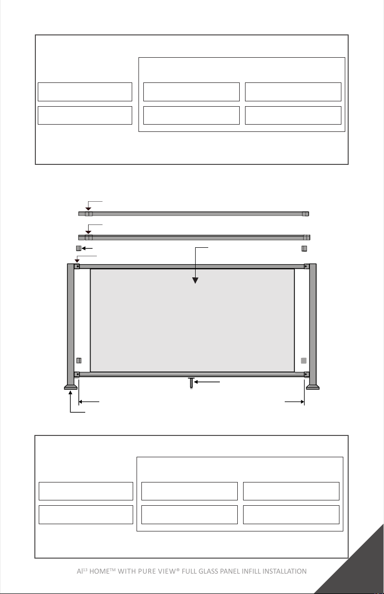
Step 3: Measure The Panel Opening Length
1. Measurethedistanceofthepanelopening.Asshownin
Fig.14.
2. Conrmthatthemeasurementsforthetopbracketsare
thesameastheboombrackets.
Note:
• Measure from the back wall of the bracket to the back
wall of the bracket on other post. As shown in Fig. 15.
CUTTING DOWN BOTTOM AND TOP RAILS
Step 1: Measure & Mark Rails Where Cuts Will Be Made
1. Takemeasurementsfoundonpage11,step3ofBracket
Installaonandmarktheselocaonswithapencilonthe
topandboomrail.
Fig. 14 Fig. 15
Measure the panel opening
Checkmeasurementwithtop
DO NOT
measure from
post
Measure
from back
of bracket
12
Al13 HOMETM WITH PURE VIEW® FULL GLASS PANEL INFILL INSTALLATION
Fig. 16
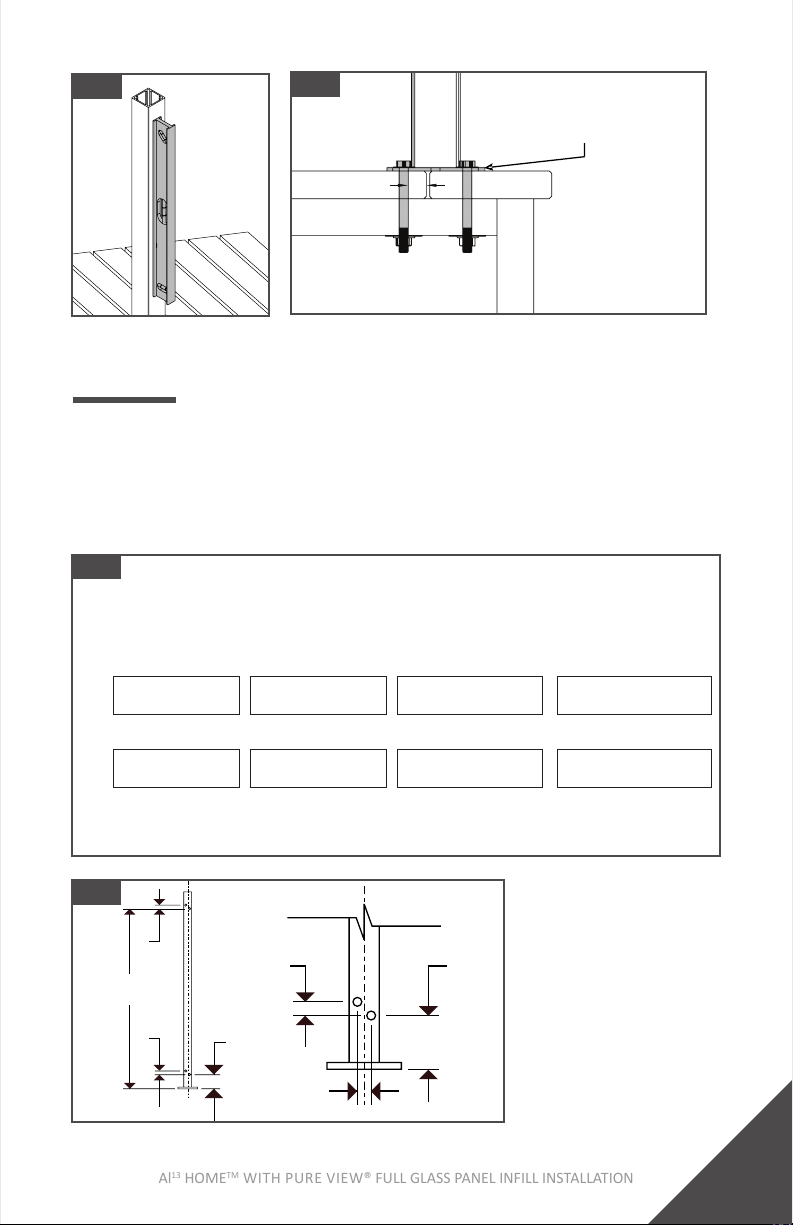
Step 2: Cut & Clean Rails
1. Cutrailsusingasawwithanetoothcarbidecung
blade.
2. Useletosmoothcutedges.
3. Removeanymetalshavingsanddustwithabrushorrag.
4. Makesuresurfacestobepaintedareclean.
4”[102mm]max
spacing on each side
Step 3: Apply Spray Paint To Cut Areas
1. Usingapieceofcardboardasamask,applythe1st coat of
Fortresszincbasedtouch-uppaint.
2. Allowtodrybeforeapplyingsecondcoat.
3. Applythe2ndcoatofFortresszincbasedtouch-uppaint.
4. Allowtodryandinstall.
Tip:
• Beforecungrails,conrmFullGlassPanelspacing.The
spacebetweenglassandpostshouldnotexceed4”
[102mm]oneachside.AsshowninFig.16.
• Totalpanelopeninglengthshouldbeglasswidthplus8”
[203mm]max.
Fig. 17 Fig. 18 Fig. 19
Al13 HOMETM WITH PURE VIEW® FULL GLASS PANEL INFILL INSTALLATION
13
Al13 HOMETM WITH PURE VIEW® FULL GLASS PANEL INFILL INSTALLATION
FULL GLASS PANEL INSTALLATION
Step 1: Install I-Support On Boom Rail
1. Measureandlocatethecenteroftheboomrail.Using
theI-Supportasaguide,markthecenterofthe2screw
holes.AsshowninFig.21.
2. Usinga3/16”[5mm]drillbit,drillthoughtheoutsidewall.
3. InstalltheI-SupportwiththeprovidedPhillipsHeadthread
cungscrews.AsshowninFig.22.
Note:
• BesuretoinstallI-Supportonsideofrailfacingdeck.
Fig. 20
2X
Fig. 21
3/16”
[5mm]
Hole
Fig. 22 Phillips
Head
Thread
Cung
Screws
Step 2: Install Boom Rail
1. Installcutboomrailintothelowerinstalledbrackets.
2. Pre-drillBracket Cup holesforscrewsusinga3/16”[5mm]
drillbit.
3. SecurerailtoBracketCupswithprovidedT-25Drive
Thread-CungScrews.Uselowspeedsengondrill.

14
Al13 HOMETM WITH PURE VIEW® FULL GLASS PANEL INFILL INSTALLATION
Fig. 23
Straight
Bracket
Cup
Al13HOMEVercalCable/
PureViewI-Support
Straight
Bracket
Cup
Fig. 24
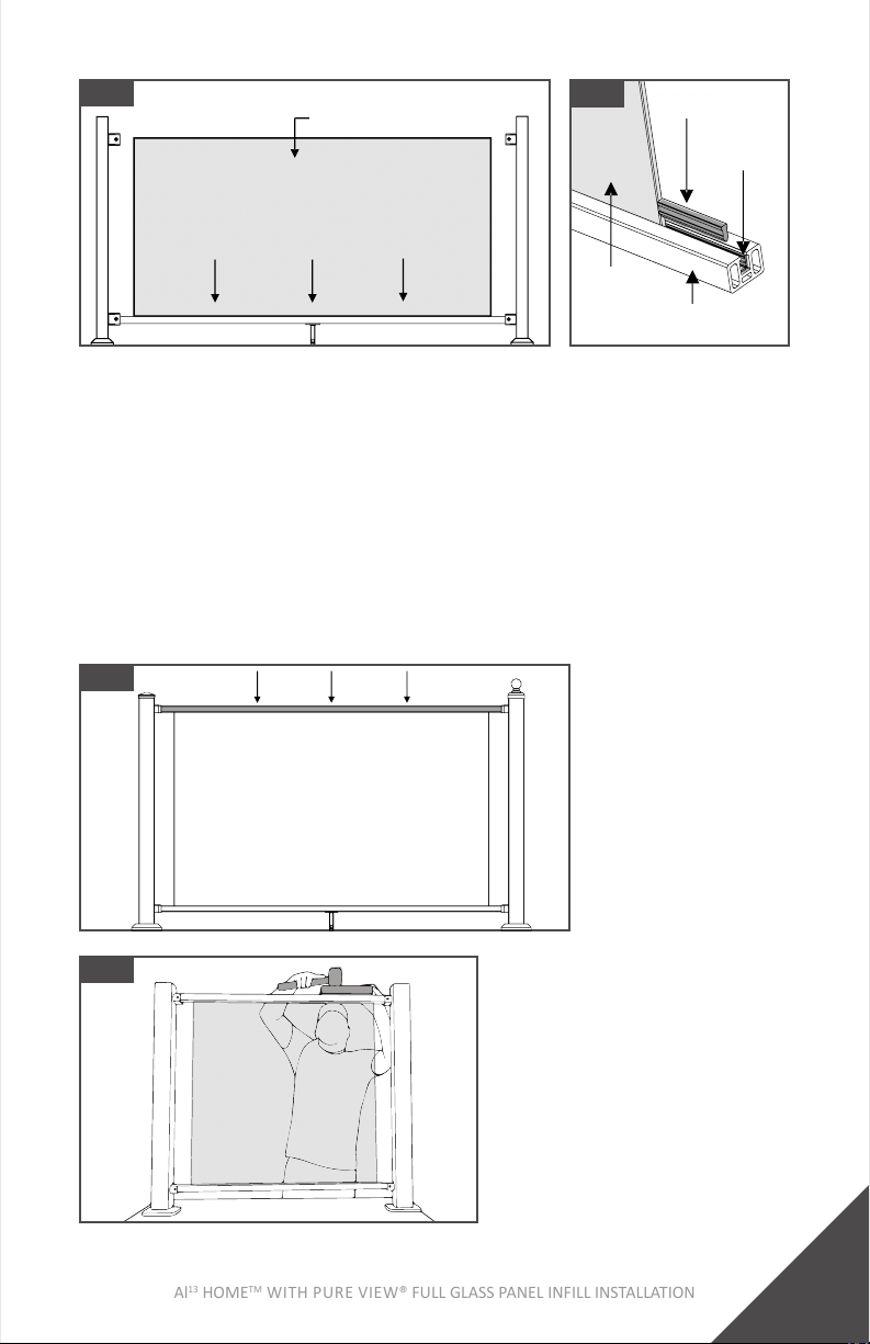
Step 3: Install Full Glass Into Boom Rail
1. Carefullyposionfullglasssheetintothecenterofthe
boomrail.AsshowninFig.26.
2. Insertspacersoneithersideoftheglassintheboomrail.
Spacerwillbeushwiththesideoftheglass.Asshownin
Fig.27.
Tip:
• Besuretowearsafetygloves&glasseswhenhandling
glass.
Set
Screw
Tip:
• It is recommended to apply a small amount of liquid soap
totheblackgasketopeningsinthetopandboomrails
beforeinstallingFullGlass.AsshowninFig.25.TheLiquid
Soaphelpstheglassseleinplace.
Fig. 25
Al13 HOMETM WITH PURE VIEW® FULL GLASS PANEL INFILL INSTALLATION
15
Al13 HOMETM WITH PURE VIEW® FULL GLASS PANEL INFILL INSTALLATION
Fig. 26
PureViewFullGlass
Fig. 27
Glass
Spacer
Step 4: Install Top Rail
1. CarefullyslipTopRailoverthetopoftheglassintothetop
BracketCups.
2. Usearubbermalletandawoodblocktodrivethetoprail
ontotheglass.AsshowninFig.29.
3. Pre-drillBracket Cup holesforscrewsusinga3/16”[5mm]
drillbit.
4. SecuretoprailtoBracketCupswithprovidedT-25Drive
Thread-CungScrews.Uselowspeedsengondrill.
BoomRail
Gasket
Fig. 28 TopRail
Fig. 29

16
Al13 HOMETM WITH PURE VIEW® FULL GLASS PANEL INFILL INSTALLATION
Step 5: Install Top Rail (Alternave)
1. CarefullyslipTopRailoverthetopoftheglassintothetop
BracketCups.
2. CarefullyslipRatchetStraps over top rail and underneath
boomrail.
3. SlowlyclampeachStrapunlglassisfullyseatedintop
rail.AsshowninFig.30.
4. Pre-drillBracket Cup holesforscrewsusinga3/16”[5mm]
drillbit.
5. SecuretoprailtoBracketCupswithprovidedT-25Drive
Thread-CungScrews.Uselowspeedsengondrill.
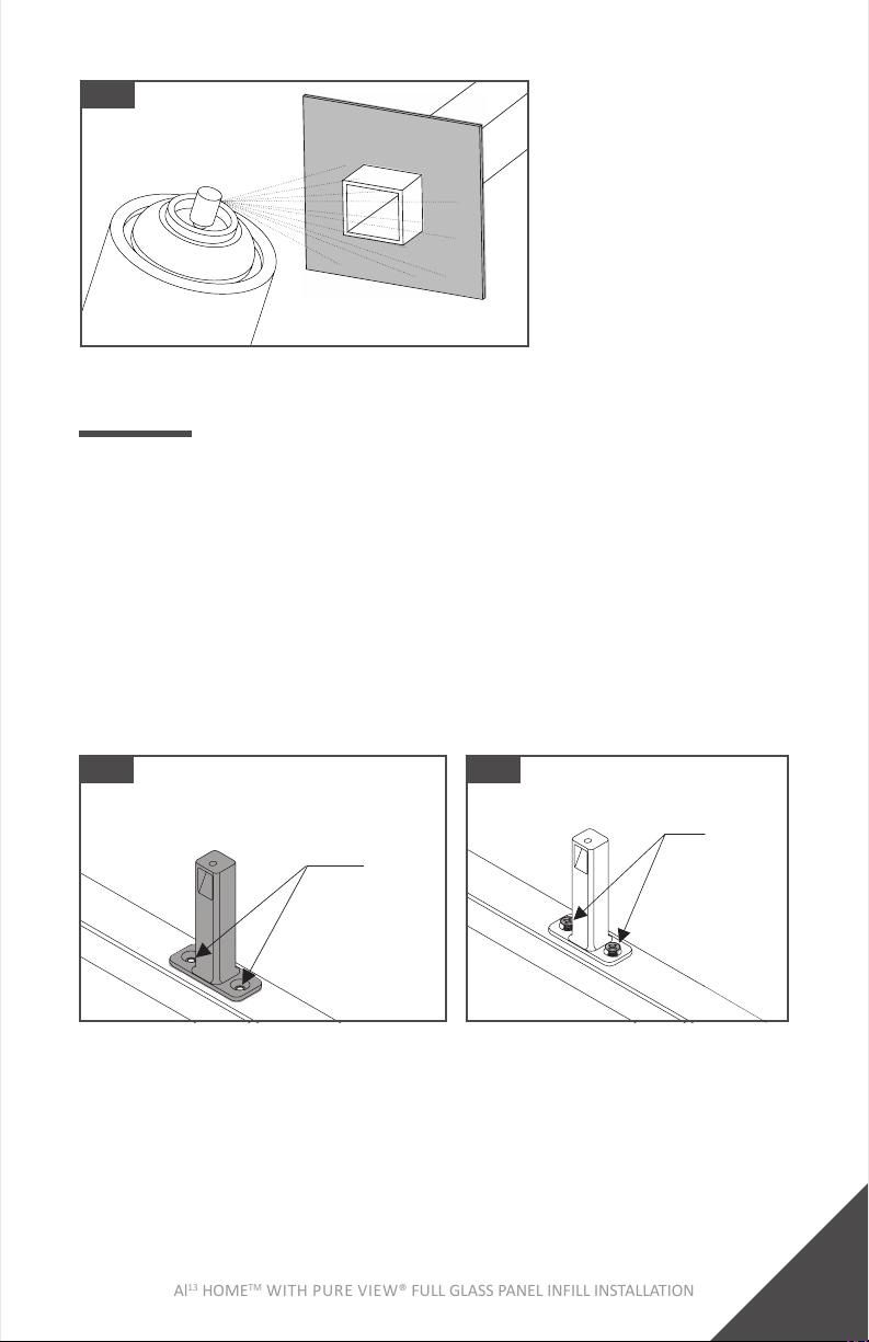
Step 6: Aach I-Support To Deck
1. FastenI-SupporttodecksurfacewiththesuppliedPhillips
HeadWoodScrew.
Tip:
• Pre-drillwitha1/16”[5mm]drillbit.
Fig. 30
Fig. 31
PureView
FullGlass
RatchetStraps

Al13 HOMETM WITH PURE VIEW® FULL GLASS PANEL INFILL INSTALLATION
17
Al13 HOMETM WITH PURE VIEW® FULL GLASS PANEL INFILL INSTALLATION
PROUD POST: ROUND ACCENT TOP RAIL (ATR)
Step 1: Round ATR Spacers
1. AachSpacersusingprovidedself-drillingscrewswitha
5/16”[8mm]nutdriver,twoscrewsperspacer.Asshown
inFig.33.
• TheAccentTopRailKitcomeswith6spacersinthe69.89”
[1775mm]kit.
• Thespacersshouldbeequallyspacedalongthelengthof
therail,withnomorethen14”[356mm]spacing
betweenthem.AsshowninFig.32.
• Theendspacersshouldbeplacedasclosetotheend
bracketsaspossible.
Note:
• DO NOT removebackingofdoublesidedtapeunlyouare
readytopermanentlyaachtheATR.
Fig. 32
DoubleSided
Tape
Fig. 33
14”[356mm]
Max
SpacerAached
NextToBracket

18
Al13 HOMETM WITH PURE VIEW® FULL GLASS PANEL INFILL INSTALLATION
Step 2: Round ATR Line & End
1. Measurethedistancefromtheinsideedgeofthe2posts.
2. CuttheATRtomeasuredlength.
3. WhentestngtheATR,placeitontopofthespacers.
DO NOTpresstheATRdownoverthespacers.Removing
theATRfromthespacerscandamagetheATRandspacers.
AsshowninFig.35.
4. Removethebackingofallofthedouble-sidedtapeonthe
ATRspacers.
5. ARubberMalletmightneedtobeusedtoinstall.Ifusinga
RubberMallet,useaclothtoprotectATRfromdamage.
Fig. 34
PROUD POST: FLAT ACCENT TOP RAIL (ATR)
Step 1: Flat ATR Spacers
1. MeasuredistancebetweenbracketsandcutATRSpacerto
length.TheSpacercanbe1/4”[6mm]shorterthanthe
distancebetweenbrackets.
Fig. 35
ATRSHOULD NOTGoPast
ThisPointWhenTestFing
Al13 HOMETM WITH PURE VIEW® FULL GLASS PANEL INFILL INSTALLATION
19
Al13 HOMETM WITH PURE VIEW® FULL GLASS PANEL INFILL INSTALLATION
2. Ifoneofthescrewholeswascutoduringthesizingof
theATRSpacer,usea5/8”[16mm]drillbittoaddan
otherhole1”[25mm]fromtheendoftheATRSpacer.
3. AachtheATRSpacerusingtheprovidedself-drilling
screwswitha5/16”[8mm]nutdriver.
4. Allscrewholesmusthaveascrewinstalled.
Note:
• Flat ATR uses a full length ATR spacer.
• DO NOT removebackingofdoublesidedtapeunlyou
arereadytopermanentlyaachtheATR.
Fig. 36
Step 2: Flat ATR Line And End
• ReferenceProudPostRoundATRLine&Endinstrucons
onpage18.
DoubleSided
Tape
Fig. 37

20
Al13 HOMETM WITH PURE VIEW® FULL GLASS PANEL INFILL INSTALLATION
OVER THE POST: ROUND ACCENT TOP RAIL (ATR)
Step 1: Round ATR Spacers
1. Aachspacersusingprovidedself-drillingscrewswitha
5/16”[8mm]nutdriver,twoscrewsperspacer.Asshown
inFig.39.
• TheAccentTopRailKitcomeswith6spacersinthe69-7/8”
[1775mm]kit.
• Thespacersshouldbeequallyspacedalongthelengthof
therail,withnomorethen14”[356mm]spacingbetween
them.AsshowninFig.38.
• Theendspacersshouldbeplacedasclosetotheend
bracketsaspossible.
Note:
• DO NOT removebackingofdoublesidedtapeunlyouare
readytopermanentlyaachtheATR.
DoubleSided
Tape
Fig. 39
Fig. 38 SpacerAached
NextToBracket
14”[356mm]
Max
Table of contents
Languages:
Popular Indoor Furnishing manuals by other brands

Levira
Levira WYE 10022.05 Assembly instructions

Itatiaia
Itatiaia IG2A-80 COOK 4B quick start guide

Indiana Furniture
Indiana Furniture Tri-One Training Table C-Leg Flip Assembly instruction

SEI
SEI Sabrina Accent OC033200TX Assembly instructions

BLUE OAK
BLUE OAK LP GAS owner's manual

Workrite Ergonomics
Workrite Ergonomics Sierra SEHX7890-4272OC Series Assembly/installation instructions

Tribesigns
Tribesigns little tree F1737 Assembly instructions

uhuru
uhuru SUMMIT CONSOLE 80" Assembly and Care

Otto
Otto 445771 Assembly instructions

International Concepts
International Concepts BD-80BUNKE Assembly instructions

Offices To Go
Offices To Go OTG13050B Assembly & operating instructions

Promeba
Promeba PS-176 user guide


