Digital Acoustics IP7-FX User manual

Page 1 of 4
IP7-FX
SIP Getting Started Guide
Introduction
The IP7-FX is a PoE powered (802.3af) IP Audio Module that can be configured as a SIP extension for use with a
SIP based phone system. The module can connect to an analog audio device such as a call station or speaker and
provides the following features
•Ethernet 10/100 Network Connector
•Port 2 10/100 available to connect another device to the network
•Eight-watt amplifier
•Microphone or Line In
•Speaker or Line Out
•Two input signals (Call and Sensor)
•Normally Open or Normally Closed Dry Contact Relay (250 VAC /
30VDC @ 60W / 1500 VAC Isolation)
•PoE (802.3af), 12VDC or 24VDC
•User configurable Full or Half duplex operation
•Standard 35MM DIN Rail Mount or optional Surface Mount Plate (included)
The IP7-FX can be configured using the eSIP Configuration utility or the TalkMaster Administrator console. This
Getting Started Guide covers basic hardware installation and software configuration of the IP7-FX.
Replacing an IP7-ST/STx, SS8/SE8, FD or SS20
If the IP7-FX is being used to replace an existing IP7-ST/STX, IP7-SS8/SE8, IP7-FD or an IP7-SS20, please note the
following:
•The J3-7 (Case) connector on older models was an extra ground. If replacing an older model with an IP7-
FX, any wire connected to J3-7 should be moved to J3-6.
•If replacing an IP7-ST/STx, make sure the internal ST-MIC switch (located on the DIN clip side) is set in
the same position. The IP7-FX does not support the Aiphone IE/ IF series call station. An IP7-ST/STx
must be used
•If the older IP7’s J2-6 (SPKR 8Ω+) and J2-7 (SPKR 8Ω-) is connected to an amplifier or amplified
speaker, use the IP7-FX’s J2-3 (Line Out) and J2-4 (GND) instead
•If replacing an IP7-SE8 / IP7-MSR-BRD with an IP7-FX, the IP7-MSR-BRD can be eliminated by changing
the IP7-FX’s ST-MIC internal switch to the ST position
•Other than the exceptions noted above, the J1, J2, J3, and network can be moved over to the IP7-FX

Digital Acoustics IP7-FX
Installation and SIP Configuration
Page 2 of 4
New Installations
The IP7-FX can be mounted indoors or outdoors in a weather tight enclosure.
•If PoE (Power over Ethernet) is not
available, connect the IP7-FX’s
Ethernet port to a network switch
using a standard RJ-45 cable.
Connect the IP7-FX to an external
12VDC (1.2 Amps) or 24VDC (2.5
Amps) power supply using either J1-
1 (+) and J1-2 (-) terminals or a
2.5mm barrel connector (center tip
positive)
•If PoE is available, connect the IP7-
FX’s Ethernet port to a PoE (802.3af) network switch or injector using a standard RJ-45 network cable. It
will request 15.4 watts from the power source equipment.
•The Link LED will turn solid. The Ready LED will begin flashing 4x per second
•The IP7-FX can use either a mic level or line level microphone. Connect a mic level microphone to the
J2-1 (Mic+) and J2-2 (Mic-) terminals. Optionally, connect a line level microphone using J3-4 (Line In),
J3-6 (Ground) and J3-7 (Mic Power –12V). Use 20-22 AWG twisted, shielded wire. The Microphone wire
cannot be in the same jacket as the speaker wire. The internal ST-MIC switch (located on the DIN clip
side) must be in the MIC position
•The IP7-FX can also use the speaker (connected to the J2-6 and J2-7 connectors) as a microphone (half
duplex mode only). To enable this mode, slide the internal ST-MIC switch (located on the DIN clip side) to
the ST position
•The IP7-FX can drive either an 8 Ohm speaker or an amplifier. Connect an 8 Ohm speaker to the J2-6 and
J2-7 (polarity independent) terminals using 18 AWG. To connect to an amplifier or self-amplified speaker,
connect the J2-3 (Line Out) to the amplifier’s “+” terminal and J2-4 (ground) to its “-“ terminal using 18 – 22
AWG. Follow any recommendations by the amplifier’s manufacture for balanced vs unbalanced audio
signals.
•The IP7-FX can initiate a SIP call by grounding the J2-5 (Talk) connector. Connect a button or switch to
J2-5 (Talk) and J2-4 (Ground) using 18 –22 AWG wire. When J2-5 is grounded, the IP7-FX will dial a
number stored in the IP7-FX configuration
•If the relay will be used to activate an electronic door strike, connect the J3-2 (COM) and either the J3-1
(NO) or J3-3 (NC) to the door strike. The relay can be activated during a call by entering a code on a
telephone keypad that is stored in the IP7-FX configuration
•The IP7-FX can be DIN rail or surface mounted. To install on a standard 35mm DIN rail using the
integrated DIN clip, tilt the top of the unit (J1, J2, J3 connectors facing up with Volume buttons facing
forward) back towards the DIN Rail until the IP7 DIN clip catches the top of the rail. Press in at the bottom
of the IP7 to snap into place). To surface mount, snap the included Mounting Plate in half, line the two
pieces (beveled holes facing up) with the screw holes on the bottom of the IP7-FX case and secure it using
the provided screws so that the mounting holes extend past the J1, J2 and J3 edge of the case
•Record the ID# from the label on back of the IP7-FX for use during software configuration.
•Optionally, the extra ID# label can be used for easy identification of this location
•Please refer to the IP7-FX_ReferenceManual available at https://www.digitalacoustics.com/support/ip7-
hardware-talkmaster-software-manuals/ for additional information on installation

Digital Acoustics IP7-FX
Installation and SIP Configuration
Page 3 of 4
SIP Configuration
If the eSIP Configuration utility has already been installed and the defaults have been setup, skip to the Select the
General Settings tab step.
Download and install the eSIP Configuration utility from https://www.digitalacoustics.com/support/software-firmware-
downloads/
•After the configuration utility has been installed, open it from the Windows® Start
menu by selecting Digital Acoustics IP7 →eSIP Configuration
•Click menu option Tools →Setup SIP Defaults to setup the default SIP based
Phone system
•In the Primary Registrar (also know as the Domain), enter the IP
Address or DNS and the port of the SIP based phone system
•The Primary Server (also known as the Proxy Address) is typically the
same as the Primary Registrar. If this is different than the Primary
Registrar, then the Registrar is Proxy box must be checked
•The Secondary Registrar and Secondary Server are only specified if a
backup VOIP based phone system is available in case the Primary fails
•The SIP Local Port and RTP Port specify the ports used by the IP7
when communicating with the VOIP based Phone system
•Press the OK button to save the defaults
Select the General Settings tab
•Press the Find Devices button to discover any new IP7 devices that
are connected to the network. The IP7 devices will be listed on the left
hand side of the screen
•Click on an IP7 Endpoint to be configured (match the Device ID
column to the Intercom’s previously recorded ID#)
•On the right hand side of the screen, select SIP Standalone Device from
the dropdown
•Enter a descriptive name into the Location Name field (this name is only
used by this utility. The description from the phone system will be used to
identify this endpoint during a call)
•Check the DHCP option to automatcally assign the IP Address infromation
or uncheck it to enter static IP address information

Digital Acoustics IP7-FX
Installation and SIP Configuration
Page 4 of 4
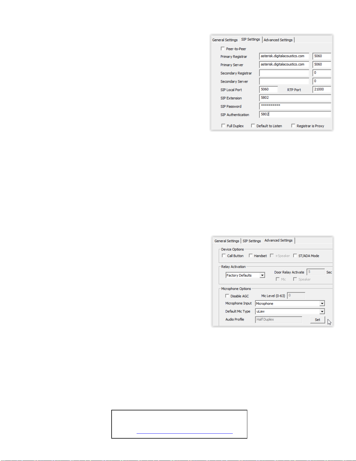
Select the SIP Settings tab
•Press the Apply Defaults button on the bottom right to copy in the
default SIP information that was previously setup
•Enter the SIP Extension, SIP Password (also known as the
Secret) that have been setup on the SIP based phone system for
this IP7 device
•In the SIP Authentication (also known as the SIP Authorization
Name), enter the User that has been associated with this extension
in the SIP based phone system. If no User has been setup, use the
same value as the SIP Extension
•Check the Full Duplex option to enable full duplex operation or
leave it blank for of half duplex
oIn a half-duplex phone call, one party has their microphone
active while the other party has their speaker active. By default,
when a call is initiated, the IP7 starts with the speaker active and
the phone operator starts their microphone active. The phone
operator can toggle the modes by pressing 0 on the phone’s
keypad. In half duplex mode, the IP7’s volume will always be
louder, and the microphone gain will always be higher
oIn full duplex mode, both parties have their speaker and microphone
active at the same time. In full duplex mode, the IP7’s volume will
always be softer, and the microphone gain will always be lower.
This is due to the algorithms used by the IP7 for echo cancellation
•Check the Outdial Extension and enter the number to be automatically dialed when the integrated Call button is
pressed
•If the integrated relay will be used to open a door during a call, specify a 1 –4 digit code in the Door Open Code to be
entered on the phone’s keypad. If the specified code has multiple digits, the phone operator will need to enter a # after
the code (using this example, phone operator would need to enter the digits 65# during the call to activate the relay). If
only a single digit is specified, the phone operator only needs to enter that digit.
Select the Advanced Settings tab
•Click the Set button next to Audio Profile and select the IP7-FX
audio profile if using full duplex. Otherwise select the Half Duplex
audio profile
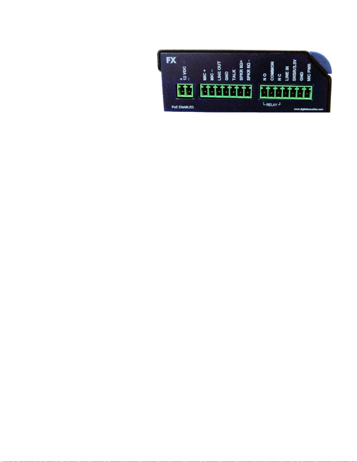
•If a microphone was connected to the Line In connectors, select Line
In from the Microphone Input dropdown box
•Click the Save Settings button. The endpoint will reboot with the
changes and register with the SIP Server within 30 seconds. The red
Call button LED on the panel will blink rapidly for 30 seconds and
then turn solid
•There are 7 volume steps that will vary based on whether a full or
half duplex audio profile has been configured. Volume can be
adjusted when a SIP call is in progress by pressing:
o#00 –Set volume down one level
o#01 –Set volume level to 1
o#02 –Set volume level to 2
o#03 –Set volume level to 3
o#04 –Set volume level to 4
o#05 –Set volume level to 5
o#06 –Set volume level to 6
o#07 –Set volume level to 7
o#08 –Set volume up one level
IP7 and Digital Acoustics® are trademarks of Digital Acoustics LLC.
Other trademarks are the property of their respective owners.
All Rights Reserved ©2019
www.digitalacoustics.com/support
Other manuals for IP7-FX
2
Table of contents
Popular Telephone manuals by other brands

Alcatel
Alcatel T26 user guide

Bell System Practices
Bell System Practices TELEHELPER Identification, Installation, Connections, Operation, and Maintenance

Connexity
Connexity M110 Quick reference guide

Zultys
Zultys ZIP 49GA quick start guide

BELGACOM
BELGACOM Forum Phone 510 user guide

Jacques
Jacques SAH-1 installation instructions