Jacques SAH-1 User manual

Installation instructions for SAH-1 SIP Phone
Telephone Base Installation
The telephone can be adapted to desktop use or mount to the wall directly or via use of a wall plate.
Installation Option –Desktop Position
1. Turn the telephone base over with the bottom side facing up. Connect the supplied Cat-5
network cable to the telephone base and route along the wire duct as shown.
CAUTION: Use only the supplied Cat-5 network cable. Cat-5 network cable is not designed
for use in any other IT devices. Misuse of Cat-5 network cable on your other IT
devices shall be prohibited. To order a replacement, contact Jacques.
2. Position the mounting bracket as shown. Insert the two small tabs of the mounting bracket
into the lower slots on the telephone base. Then press the large tab on the mounting bracket
and firmly push it into the upper groove on the telephone base.
3. Once the telephone base has been installed base as shown below, connect the coiled
handset cord to the telephone base.
51837

4. Once installed, the telephone begins a four-step initialization and system registration process.
(1) The MUTE key and IN USE lights turn on and then go off.
(2) The MUTE key flashes.
(3) The MUTE key stops flashing.
(4) The MESSAGE WAITING LED, MUTE and IN USE lights illuminate for 500ms when
initialization and system registration are successful.
NOTE: In order for the phone to initialise successfully, configuration via the devices web page
may be required. Please refer to JCN-0347 for information related to device
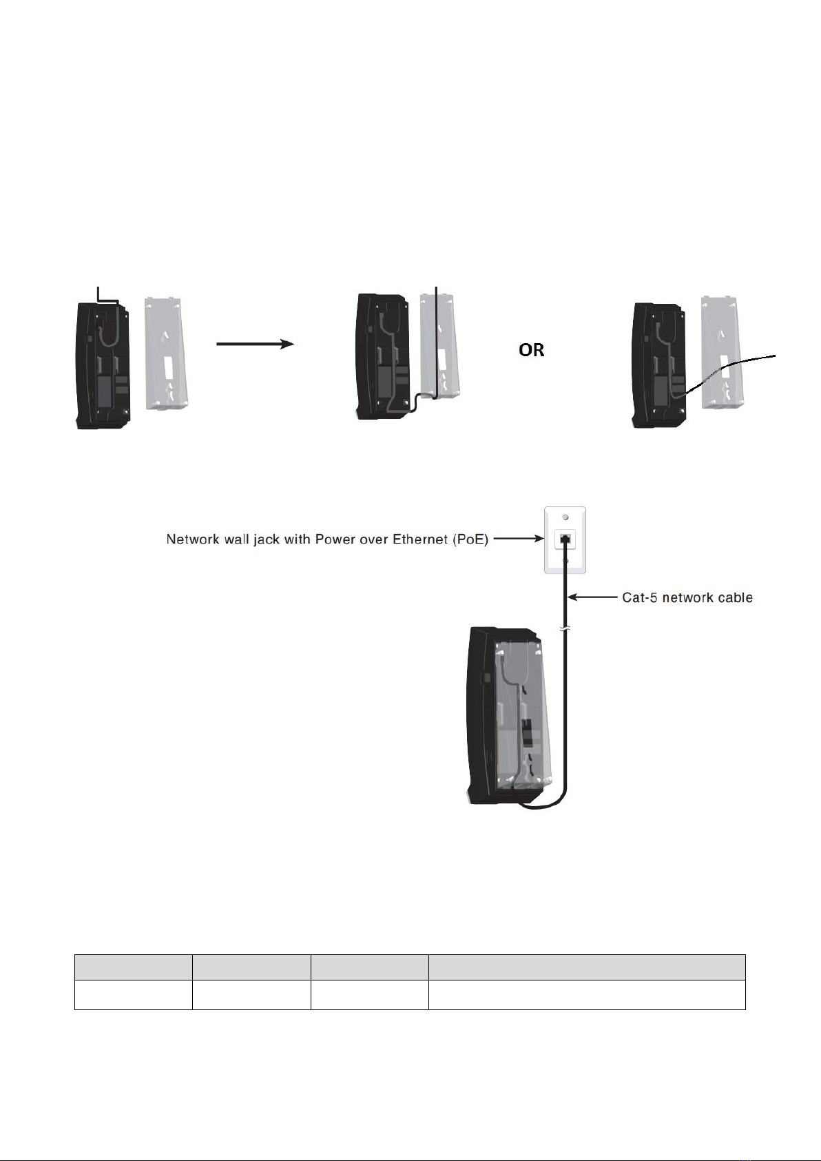
configuration. If the system registration fails, the IN USE key blinks twice every second.
To reset, disconnect the Cat-5 network cable from the network wall jack with Power over
Ethernet (PoE) and connect it back again.
Installation Option –Converting from Desktop to Wall Mount Position
To mount the telephone base on the wall:
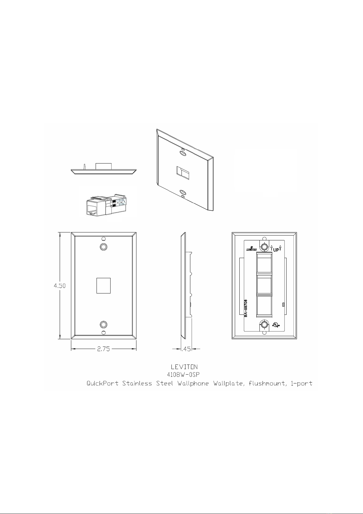
1. Ensure suitable mounting screws or wall mounting plate are installed in correctly in the
location you intend to wall mount the unit. Ensure a source of network access and PoE are
located nearby. Please refer to appendix A and B for suggested mounting methods.
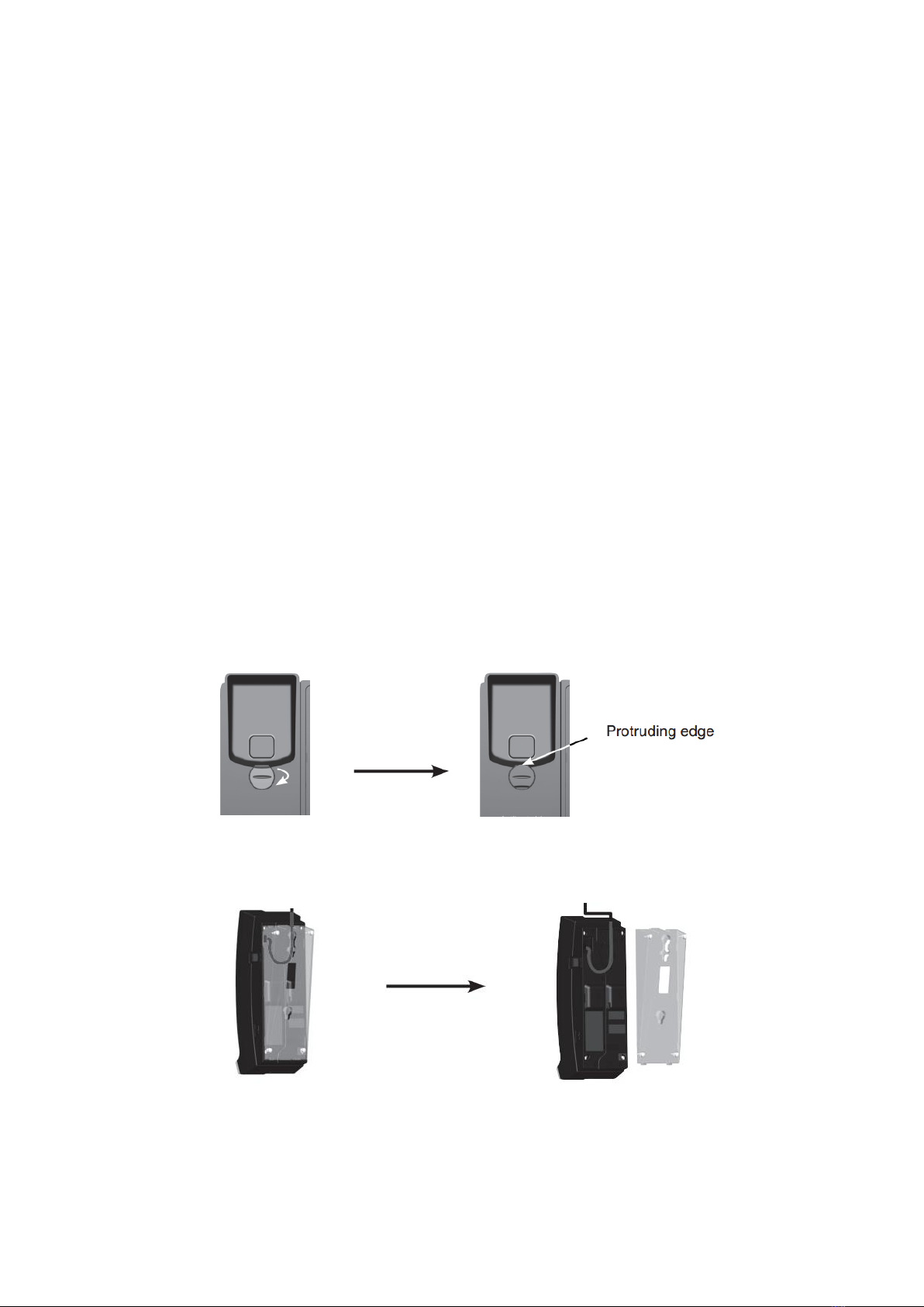
2. Put the corded handset aside. On the telephone base cradle, place a coin in the slit of the
wall mount clip and rotate a half turn (180 degrees). It locks into place with the protruding
edge pointing towards the upper edge of the telephone base. This protruding edge holds the
corded handset when the phone is mounted on the wall.
3. Unplug the Cat-5 network cable from the network wall jack. Then press the large tab on the
mounting bracket to remove it from the upper groove on the telephone base.

4. Turn the mounting bracket upside down. Remove the Cat-5 network cable from the wire duct
and then route it through the groove on the bottom part of the mounting bracket or
alternatively through the cutout located between the two mounting key hole slots. Insert the
small tabs on the mounting bracket into the upper slots on the telephone base. Then press
the large tab on the mounting bracket and firmly push it into the lower groove on the
telephone base.
5. Connect the Cat-5 network cable to the allocated network wall jack.
6. Mount the telephone base on the wall by aligning the mounting key hole slots with the
mounting studs on the wall or wall plate. Then slide the telephone base down on the mounting
studs until it locks into place. Place the handset on the telephone base cradle and connect the
coiled handset cord to the telephone base if not already done.
Revision
Date
Author
Change Description
1.0
2016-12-08
LM
Initial Release.

APPENDIX A - Wall Mounting Plate Option
Jacques recommends that you use the Leviton Wall mount plate (Leviton type number: 4108W-SP)
for mounting the S2211 SIP phone. This particular wall mounting plate is design to accommodate
Leviton’s QuickPort series of RJ45 keystone. The wall mount plate is not provided by Jacques.

APPENDIX B –Direct Wall Mounting Option
In the case of installation whereby the installer has opted not to use wall mounting plates, the
following diagram provides details for positioning mounting studs and cut-out regions for cable entry.
Jacques suggests using M4 pan head screws or similar solutions for acting as mounting studs. The
head of the mounting stud should ideally be between 8 - 9mm in width and separated from the wall by
approximately 4mm. Please ensure that the item used is designed specifically for fastening to wall
material present at the installation site. Jacques does not take any responsibility for damages
occurred as a result of the installer’s selection of mounting hardware.
Table of contents