Digital Control Systems M380 User manual

M380 Networked CO
2
Sensor/Transmitter
with Relay
User’s Manual
Digital Control Systems, Inc.
6475 SW Fallbrook Pl.
Beaverton, OR 97008 • USA
www.dcs-inc.net • 503/246-8110

M380 CO2User’s Manual
Last Rev Date: 3/07/23
Digital Control Systems, Inc. Page: 2
6475 SW Fallbrook Pl • Beaverton, OR 97008 • USA
90-0006-00
www.dcs-inc.net • 503/246-8110
Table of Contents
Feature Overview............................................................................................................................ 3
CO
2
Sensor.................................................................................................................................. 3
Relay........................................................................................................................................... 3
BACnet ....................................................................................................................................... 3
Modbus ....................................................................................................................................... 3
Network Topology...................................................................................................................... 4
NEARcom................................................................................................................................... 4
Calibration .................................................................................................................................. 4
Specifications.................................................................................................................................. 5
Installation....................................................................................................................................... 6
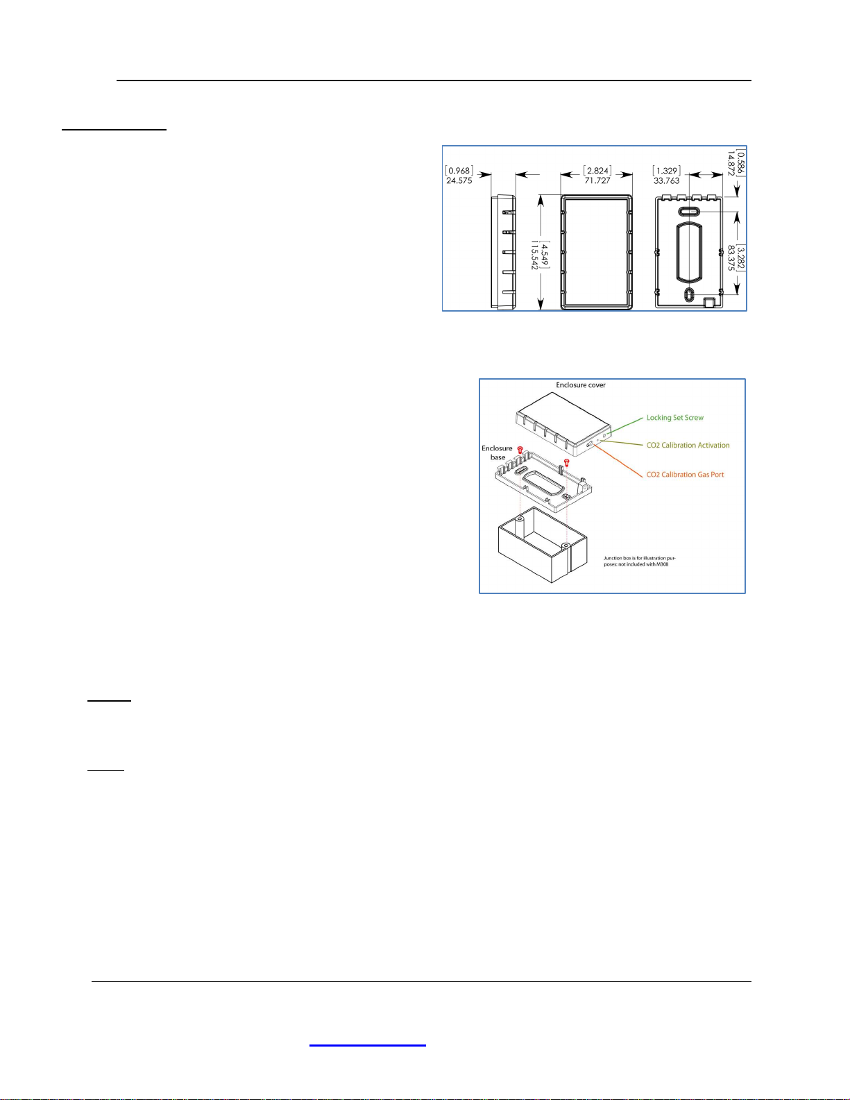
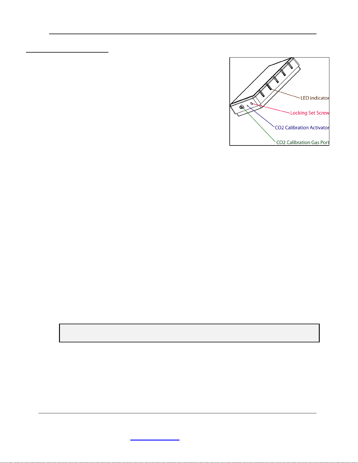
Mechanical.................................................................................................................................. 6
Wiring......................................................................................................................................... 6
Power ...................................................................................................................................... 6
Relay....................................................................................................................................... 6
Network Connection............................................................................................................... 7
Configuration.................................................................................................................................. 9
NEARcom................................................................................................................................... 9
Inspecting the M380 Settings................................................................................................ 10
Configuring the M380 Settings............................................................................................. 10
Configuration Procedure........................................................................................................... 11
Example configuration – BACnet......................................................................................... 12
Example configuration – Modbus......................................................................................... 13
Operation....................................................................................................................................... 14
Relay......................................................................................................................................... 14
CO
2
Sensor................................................................................................................................ 14
BACnet ..................................................................................................................................... 14
Modbus ..................................................................................................................................... 14
Calibration Sequence.................................................................................................................... 16
Disclaimers ................................................................................................................................... 17
Life Safety................................................................................................................................. 17
Warranty ....................................................................................................................................... 17
Appendix 1: BACnet objects and default values.......................................................................... 18
Device Object ........................................................................................................................... 18
CO2 - Analog Input Object 1.................................................................................................... 19
Relay – Binary Output Object 1 ............................................................................................... 20
Relay Setpoint - Analog Value Object 1 .................................................................................. 21
Enable Local Relay Control - Binary Value Object 1 .............................................................. 21
Appendix 2: Modbus registers..................................................................................................... 22
Appendix 3 - 3rd Party Software Components & Licenses.......................................................... 23
Revision History ........................................................................................................................... 24

M380 CO2User’s Manual
Last Rev Date: 3/07/23
Digital Control Systems, Inc. Page: 3
6475 SW Fallbrook Pl • Beaverton, OR 97008 • USA
90-0006-00
www.dcs-inc.net • 503/246-8110
Feature Overview
The M380 is a network-capable CO
2
sensor/transmitter with a single relay that can be set to
use either local concentration-based or network-controlled actuation. The M380 can
communicate using BACnet MS/TP, Modbus RTU, or Modbus ASCII, all using an RS-485
interface. The M380 is equipped with a dual beam CO
2
sensor for long-term accuracy
without the need for frequent re-calibration. Configuration of settings is accomplished using
the DCS NEARcom app with an NFC-capable smartphone for easy ‘fill in the blanks’
network setup.
CO
2
Sensor
The M380 uses a self-compensating ‘dual beam’, NDIR (NonDispersive InfraRed) CO
2
detection system which uses a second IR detector to measure and eliminate the major inherent
drift mechanisms (source amplitude degradation and sensor-wall reflectivity changes) for
greatly enhanced long-term accuracy. To achieve comparable accuracy, single beam systems
need ‘self-calibration’ algorithms that can be wildly inaccurate in changing building
occupancy profiles. The M380 can be used in any building occupancy profile with no
compromise in long-term accuracy.
Relay
The M380 has a dry-contact, 2-Amp capable pilot relay that can be controlled by two different
mechanisms; local setpoint or network control. With setpoint control, the relay is controlled
locally by the device based on the current CO
2
setpoint. Network control passes control of the
relay to the active network interface where it is modeled either as a binary output (BACnet) or
a holding register (Modbus).
BACnet
BACnet (Building Automation and Control network) is a standardized communication
protocol used for building automation created by ASHRAE (American Society of Heating,
Refrigeration, and Air-Conditioning Engineers). BACnet specifies a vendor-neutral set of
models and messages that enable equipment from multiple manufacturers to be integrated
within the same control network. BACnet can use several different physical communication
systems depending on the constraints of the system, the most common being BACnet/MSTP
and BACnet/IP. Most end devices only support one transport layer, although bridges are
available that can translate messages between different transport layers.
The M380 supports only BACnet/MSTP.
Modbus
Modbus is an industrial control protocol. It has somewhat less overhead than BACnet,
allowing fewer data types and providing less context information about modeled objects. In
Modbus all data is held in registers that can be read or written to interact with the values they
model (e.g., CO
2
reading, relay state, etc.). A single client device sends requests to servers.
Servers will not initiate communication unless they are directly addressed.
Modbus implements several modes of communication; RTU, ASCII, and TCP all using the
same data model. Modbus RTU (remote terminal unit) and Modbus ASCII both use
asynchronous serial communication protocols for their physical layers (typically RS485) and
differ mainly in how data is encoded, RTU being more efficient and ASCII being somewhat
more readable.
The M380 communicates only via RS-485.

M380 CO2User’s Manual
Last Rev Date: 3/07/23
Digital Control Systems, Inc. Page: 4
6475 SW Fallbrook Pl • Beaverton, OR 97008 • USA
90-0006-00
www.dcs-inc.net • 503/246-8110
Network Topology
The M380 uses RS-485 as its physical transport layer. Individual network elements are
connected with a single twisted-pair of conductors, often covered by a metal shield. All
network elements are wired in a ‘daisy chain’ configuration as shown in Figure 5. Only the
units at the ends of the chain have a terminating resistor connected between the two data lines.
NEARcom
NEARcom is a free app for Android and iOS phones equipped with near-field communication
(NFC). NEARcom creates a virtual front panel for the M380 on a phone, and allows the user
to view and make changes to the device’s settings.
Using the NEARcom app is simple and intuitive: the user simply launches the app and briefly
holds the phone near the front of the M380 to read the device’s current settings. After reading
the M380, the user can take the phone away from the device to view and make any desired
changes to the settings. After all setting adjustments are complete, the user briefly holds the
phone near the front of the M380 and the new settings are transferred back to the device.
Changes to the M380 using the NEARcom app can be made while the device is
unpowered (prior to installation) or while the devices is powered and operating
normally.
Refer to the Configuration section for more detailed information.
Calibration
Although the M380’s dual-beam CO
2
sensor does not need frequent calibration, it does
support a single-point calibration using 2000 ppm CO
2
(balance air or nitrogen) calibration
gas. A calibration kit is available from your HVAC instrumentation supplier or directly from
Digital Control Systems. The calibration kit contains a compressed calibration gas cylinder
(with pressure above 100 psi), a pressure regulator that fits onto the cylinder, and 1/4-inch OD
plastic tubing that is connected to the calibration port on the M380 (refer to Figure 2 for
calibration port location).
For accurate calibration, it is essential to keep a low flow rate of the calibration gas into the
sensor during the single-point calibration process: a flow rate of 100 to 120 ml/min
(milliliters/minute) is ideal. Significantly higher flow rates risk bursting the sensor’s diffusion
port filter membrane. Adjustments to the pressure regulator should be made to create the
required low-pressure, weak-flow gas stream. Refer to the Calibration Sequence section
included in this document for more details.

M380 CO2User’s Manual
Last Rev Date: 3/07/23
Digital Control Systems, Inc. Page: 5
6475 SW Fallbrook Pl • Beaverton, OR 97008 • USA
90-0006-00
www.dcs-inc.net • 503/246-8110
Specifications
Parameter Value
Communication Protocols BACnet MS/TP, Modbus RTU, Modbus ASCII
Supported Baud Rates 9600, 9200, 38400, 76800, 5200
Sensor Operating Principle Dual-beam, non-dispersive infrared (NDIR)
Gas Sampling Method Diffusion through sub-micron particle filter
Measurement Range 0-2000ppm (0-5000 ppm optional)
Repeatability ± 20 ppm CO2
Measurement Accuracy ± 30 ppm ± 2% of reading
Calibration One point: single gas calibration
Recommended Calibration
Interval 5 years
Warm-up Time Less than Minute
Power Requirements 5 - 40 VDC or 8 - 28 VAC RMS
Power Consumption Less than 3 Watts
Operating Temperature
Range 0 - 50° Celsius
Operating Humidity Range 5 - 95% RH, non-condensing
Enclosure Dimensions 4.5" x 2.8" x .0" ( 6 x 72 x 25 mm) Wall mounting
Enclosure Material White Satin Finish, ABS Plastic
UL 94 V-O Flammability Rated
Relay SPDT, Dry contact, Max rating 2A at 24VDC or 24VAC
Warranty 3-year for sensor, 7-year for electronics
Table 1: M380 Specifications.

M380 CO2User’s Manual
Last Rev Date: 3/07/23
Digital Control Systems, Inc. Page: 6
6475 SW Fallbrook Pl • Beaverton, OR 97008 • USA
90-0006-00
www.dcs-inc.net • 503/246-8110
Installation
Mechanical
The M380 conveniently mounts onto a
standard single-gang electrical box, with
wiring entering the enclosure through the
access opening in its base (refer to Figure
2). The same mounting holes can be
used to affix the M380 onto a flat vertical
surface with appropriate fasteners.
The unit is usually mounted vertically in
an electrical box; however, it will
function with slightly degraded accuracy
in any orientation.
Wiring
Feed wires through the enclosure base, then
mount the base onto a junction box or directly
to the wall. Connect wires to screw terminals
on the circuit board as shown in Figure 3; the
connectors are removable for easier wire
landing, and keyed so that they can only be
inserted into the socket in the correct
orientation.
Align the slots in the top of the enclosure cover
with the tabs on the enclosure base and snap it
closed. Back out the set screw (located on the
bottom of the cover and shown in Figure 2) to secure the enclosure cover using a 3/32” Allen
wrench.
Power
The M380 uses a full bridge rectifier allowing the power supply to be connected without
concern for polarity. Refer to the Power Requirements in Table 1 for further information.
Relay
The single-pole double-throw (SPDT) relay connection terminals are shown in Figure 3. This
is a low-voltage pilot-relay – DO NOT CONNECT TO LINE VOLTAGE.
When the relay is inactive the common (COM) terminal will be connected to the normally
closed (NC) terminal and the normally open (NO) terminal will not be connected.
When the relay is active the common terminal will be connected to the normally open
terminal and the normally closed terminal will not be connected.
Figure 2: Attaching to single-gang electrical box.
Figure 1: Case Dimensions (mm &[in]).

M380 CO2User’s Manual
Last Rev Date: 3/07/23
Digital Control Systems, Inc. Page: 7
6475 SW Fallbrook Pl • Beaverton, OR 97008 • USA
90-0006-00
www.dcs-inc.net • 503/246-8110
Network Connection
The network (BACnet or Modbus) data
lines should be connected in a daisy
chain configuration with no stubs or
branches as shown in Figure 5. The
network data interconnection is a
twisted-pair of two wires (sometimes
shielded) which are not interchangeable
and must not be confused with each
other during installation.
In most installations there will be both
incoming and outgoing data pairs which need to be connected. It is critical that both A-
conductors (one each from the incoming and outgoing connection) be connected to the
A- terminal, and both B+ conductors to the B+ terminal.
If the unit being installed is the first or
last unit on the chain (i.e. there are only
single A- & B+ wires) the end-of-line
resistor should be enabled by setting the
EOL jumper (see Figure 4) to the EOL
position with the shorting block on the
left. Only the first and last devices in
the daisy chain should have EOL
termination enabled.
The shield connection on the terminal is
provided for convenience in splicing
cable shielding together. It is not
electrically connected to the M380 and
using the connector to couple the shields is optional. The shield for the entire trunk should be
tied to ground only at a single point, typically the BAS.
Figure 4: Data line termination jumper.
LEFT - EOL termination enabled.
RIGHT - EOL termination disabled.
Figure 3: Wiring diagram showing connections.

M380 CO2User’s Manual
Last Rev Date: 3/07/23
Digital Control Systems, Inc. Page: 8
6475 SW Fallbrook Pl • Beaverton, OR 97008 • USA
90-0006-00
www.dcs-inc.net • 503/246-8110
Figure 5: BACnet Network Topology
Top: Properly routed network with no stubs and EOL termination only at the two ends of the network.
Bottom: Improperly routed network with branch and stub connections as well as improper termination
(both enabled mid-chain and disabled at the terminals)
.

M380 CO2User’s Manual
Last Rev Date: 3/07/23
Digital Control Systems, Inc. Page: 9
6475 SW Fallbrook Pl • Beaverton, OR 97008 • USA
90-0006-00
www.dcs-inc.net • 503/246-8110
Configuration
Because of the relatively complex setup required to configure a networked sensor, the
configuration is done through a graphical user interface (GUI) on either an Apple or Android
smart phone with Near Field Communication (NFC). NFC is a popular, short-range wireless
technology that allows a smart phone to communicate with an external device. Most modern
smart phones are equipped with NFC as this is commonly used to allow a phone to act as a
transit pass, or for wireless payment.
The NEARcom app uses NFC to quickly and intuitively configure the M380; this app is
freely available from either the Apple App-Store or Google Play.
https://apps.apple.com/app/id1595984749
https://play.google.com/store/apps/details?id=net.dcsinc.bacnetconfiguration
NEARcom
The free NEARcom app is used to review and configure
the M380 settings by providing a short-range link
between a smart phone and the M380. The M380
settings are transferred to the phone by holding the phone
up to the front cover (with the middle-back of the phone
near the area indicated in Figure 6). After the settings
have been transferred, the phone can be taken away so
that the current settings can be inspected and altered from
a comfortable position. After changes are made, the
phone is placed near the M380 antenna (shown in Figure
6) again to transfer the new settings to the M380.
The configuration settings can be inspected and
changed while the M380 is unpowered (prior to
installation), or while it is powered and running normally. If the M380 is powered when
changes are made there may be a short delay (less than 10s) before the changes are applied.
Refer to the following section for details on using NEARcom to inspect and adjust the M380’s
settings.
Figure 6: Approximate location of the
M380’s NFC
antenna.

M380 CO2User’s Manual
Last Rev Date: 3/07/23
Digital Control Systems, Inc. Page: 10
6475 SW Fallbrook Pl • Beaverton, OR 97008 • USA
90-0006-00
www.dcs-inc.net • 503/246-8110
Inspecting the M380 Settings
This process can be done with M380 powered or unpowered
(prior to installation). Before proceeding, download and
install the NEARcom app from the Apple App-Store or from
the Google Play Store.
1. If an Android phone is being used, ensure NFC turned on:
refer to the phone’s manual for more information.
2. Locate and launch the NEARcom app (refer to Figure 7):
the app will display “Read settings to make configuration
changes.”
3. Press the “Read” button located at the top of the app; the app will instruct the user to hold
the phone over the M380.
4. Hold the middle-back of the phone near the area indicated in Figure 6. After the transfer
is complete, the phone can be moved away from the M380, and the app will display all of
the M380’s current settings.
Configuring the M380 Settings
1. Follow the steps outlined in Inspecting the M380 Settings section above: no setting
configurations are allowed until the current device settings have been retrieved.
2. Locate the setting to be adjusted. Select a setting by touching it, then make the desired
changes: multiple settings can be changed before transferring them back to the M380.
When settings are changed, their fields will be highlighted to indicate they will be
updated during the next Write transfer.
3. Press the “Write” button located at the top of the app: the app will display a message
instructing the user to hold the phone over to the M380 to transferring the new settings.
NOTE: the “Write” button will be grayed out and inactive until a change to the settings
have been made.
4. Place the middle-back of the phone over the area indicated in Figure 6 and hold it in this
location until the prompt is removed.
NOTE: moving the phone away from the M380 too early will abort transferring the new
setting and an error message will be displayed. If this occurs, dismissed the error
message, place the phone over the M380 and hold it place until the transfer is complete.
Figure 7: NEARcom App Icon
.

M380 CO2User’s Manual
Last Rev Date: 3/07/23
Digital Control Systems, Inc. Page: 11
6475 SW Fallbrook Pl • Beaverton, OR 97008 • USA
90-0006-00
www.dcs-inc.net • 503/246-8110
Configuration Procedure
Network
Type Parameter Name Value Description
Both Baud Rate 9600, 19200, 38400,
76800, 115200 Network communication speed.
Communication
Mode BACnet, Modbus Network type selection.
BACnet
MSTP Address 0 to 127 Must be unique in the network and
less than or equal to the value of
MSTP Maximum Master.
Maximum Master 1 to 127 Must greater than or equal to MSTP
Address.
Device Instance 0 to 4194302 Must be unique in the network.
Device Name Limited to 50
characters Text field for user input of a device
name.
Device Location Limited to 50
characters Text field for user input describing
the device’s location.
Device
Description Limited to 50
characters Text field for user input of
description.
Modbus
Modbus Mode RTU, ASCII Transmission mode of message in
network.
Modbus Address 1 to 247 Must be unique on the subnet.
Modbus Parity Even, Odd, None Communication parity bit.
Table 2: Configuration parameters for BACnet and Modbus network.
Device Configuration
Parameters Value Description
Relay Control Method Remote or Setpoint
Remote: the network has control of
the M380 relay actuation.
Setpoint: the M380 has control of
relay actuation based on the value of
CO
2
Alarm Setpoint.
CO
2
Alarm Setpoint (ppm) 0 to 5000
The M380 relay will actuate when the
CO
2
concentration rises above this
setting (refer to Relay in the
Operation section for more details).
Table 3: Device configuration parameters.

M380 CO2User’s Manual
Last Rev Date: 3/07/23
Digital Control Systems, Inc. Page: 12
6475 SW Fallbrook Pl • Beaverton, OR 97008 • USA
90-0006-00
www.dcs-inc.net • 503/246-8110
Before beginning the configuration process:
1. Determine and record the parameters needed for your installation: a list of the parameters
for a BACnet or Modbus network is shown in Table 2.
2. Determine out the M380 relay will be controlled (refer to Table 3 for more information).
NOTE: All M380 BACnet parameters for any previously configured units can easily be
determined; refer to Inspecting the M380 Settings in the Configuration section of this
manual.
Example configuration – BACnet
For this example, the M380 is being configured while it is unpowered (prior to installation).
The process is the same if the M380 is powered; however, the installer should ensure the
MSTP Address and Device Instance are unique before the M380 is attached to an existing
network.
1. Launch the NEARcom app and read the current settings by pressing the Read button at
the top of the screen and holding the phone near the M380 (refer to Inspecting the M380
Settings in the Configuration section of this manual). No setting changes can be made
until this step is complete.
2. Touch Baud Rate and set this parameter the value used by the rest of the network (9600,
19200, 38400, 76800, or 115200).
3. Set the Communication Mode parameter to BACnet: this will cause all BACnet specific
parameters to be shown and all of the unused Modbus parameters are hidden.
4. Set the MSTP Address to the desired value: this address is the physical-layer address that
identifies the M380 being installed to the network and must be unique to the MSTP
network segment.
5. Set the Maximum Master parameter to the desired value; this value must be greater-than
or equal-to the MSTP Address setting. The value of Maximum Master is the highest
MSTP address to which the M380 will attempt to pass the MSTP token. This value must
be unique to the MSTP subnet that the device will use.
6. Set the Device Instance to a unique value for the entire BACnet internetwork (value
ranges from 0 to 4194302).
7. Select and enter desired text for the Device Name, Device Location, and Device
Description parameters: these parameters can be left empty or contain up to 50
characters.
8. Select desired setting for Relay Control Method (Remote or Setpoint). If using Setpoint,
enter a value the for CO
2
Alarm Setpoint parameter (refer to Table 3).

M380 CO2User’s Manual
Last Rev Date: 3/07/23
Digital Control Systems, Inc. Page: 13
6475 SW Fallbrook Pl • Beaverton, OR 97008 • USA
90-0006-00
www.dcs-inc.net • 503/246-8110
9. Transfer the new settings to the M380 by pressing the Write button at the top of the
screen, then hold the phone near M380 until the setting are completely transferred. Refer
to Configuring the M380 Settings section in this manual for more details.
NOTE: Settings are NOT changed within the M380 until this step is complete. If
desired, the new settings can be verified directly after they have been transferred to the
M380 by following steps outlined in the Inspecting the M380 Settings section of the
manual.
Example configuration – Modbus
For this example, the M380 is being configured while it is unpowered (prior to installation).
The process is the same if the M380 is powered; however, the installer should ensure the
Modbus Address is unique before the M380 is attached to an existing network.
1. Launch the NEARcom app and read the current settings by pressing the Read button at
the top of the screen and holding the phone near the M380 (refer to Inspecting the M380
Settings in the Configuration section of this manual). No setting changes can be made
until this step is complete.
2. Touch Baud Rate and set this parameter the value used by the rest of the network (9600,
19200, 38400, 76800, or 115200).
3. Set the Communication Mode parameter to Modbus: this will cause all Modbus specific
parameters to be shown and all of the BACnet specific parameters are hidden.
4. Select the Modbus Mode that is being used by the rest of the network (RTU or ASCII).
5. Set the Modbus Address (1 through 247): this address is the physical layer address and
must be unique to prevent multiple devices from attempting to respond to queries.
6. Select the Modbus Parity setting that the rest of the network is using (Even, Odd, or
None).
7. Select desired setting for Relay Control Method (Remote or Setpoint). If using Setpoint,
enter a value the for CO2 Alarm Setpoint parameter (refer to Table 3).
8. Transfer the new settings to the M380 by pressing the Write button at the top of the
screen, then hold the phone near M380 until the setting are completely transferred. Refer
to Configuring the M380 Settings section in this manual for more details.
NOTE: Settings are NOT changed within the M380 until this step is complete. If
desired, the new settings can be verified directly after they have been transferred to the
M380 by following steps outlined in the Inspecting the M380 Settings section of the
manual).

M380 CO2User’s Manual
Last Rev Date: 3/07/23
Digital Control Systems, Inc. Page: 14
6475 SW Fallbrook Pl • Beaverton, OR 97008 • USA
90-0006-00
www.dcs-inc.net • 503/246-8110
Operation
Relay
The relay can be controlled by two different mechanisms, setpoint control based on the CO
2
reading or network control(default).
When the relay is driven based on the setpoint, it will be inactive until the CO
2
concentration
rises 10 ppm above the Relay Setpoint. Once the relay is active, it will not transition to
inactive until the CO
2
concentration falls 10 ppm below the Relay Setpoint.
Under network control the relay state is determined solely by the network and is not
responsive to local CO
2
concentration. The mechanism of network relay control varies based
on which communication protocol is being used; if BACnet is enabled, the M380 controls the
relay based on the binary output object (BO1) using a priority array. If Modbus is enabled,
the relay is driven based on the “Relay state” register (4004).
CO
2
Sensor
There is a 10s delay at startup before readings are available, during this time the CO
2
will read
0 ppm. If setpoint control is enabled, the relay will be inactive during startup to allow time
for the CO
2
sensor to initialize. After this startup delay, the CO
2
reading is updated once ever
second.
BACnet
A complete list of the objects available on the M380 is available starting in Appendix 1 of this
manual.
The M380 will initiate a single i-am message after power-up to enable faster network
discovery, but otherwise will not initiate any network traffic (except MSTP level token
passing and polling for masters) without being queried.
If optional hardware, such as the relay, is absent then the Reliability propery for the
corresponding object will indicate this.
None of the objects support event state reporting and Event_State for all object will always
read Normal (0).
Modbus
The M380 uses either Modbus RTU or ASCII and supports even, odd, and no parity. The
default settings are Modbus RTU with even parity.
Each frame is formatted based on settings as shown below in Table 4.
The Modbus register table is available in Appendix 2, Table 5 of this manual. All registers are
modeled as holding registers. If a register is listed as read-only then any attempts to write to
the register will receive an error response.
Registers can be read with function code 3 (read holding register) and written with function
code 6 (write single register). Attempts to write to a read-only register will receive an error
response with exception code 4.
The mode, parity, device address, and baud rate are set using the configuration application.

M380 CO2User’s Manual
Last Rev Date: 3/07/23
Digital Control Systems, Inc. Page: 15
6475 SW Fallbrook Pl • Beaverton, OR 97008 • USA
90-0006-00
www.dcs-inc.net • 503/246-8110
Mode
setting
Parity
setting
Start
bits
Data
bits
Parity
bits
Stop
bits
RTU
Even 8
Odd 8
None 8 0 2
ASCII
Even 7
Odd 7
None 7 0 2
Table 4: Modbus Data Formatting

M380 CO2User’s Manual
Last Rev Date: 3/07/23
Digital Control Systems, Inc. Page: 16
6475 SW Fallbrook Pl • Beaverton, OR 97008 • USA
90-0006-00
www.dcs-inc.net • 503/246-8110
Calibration Sequence
During calibration the BACnet CO
2
Analog Input object’s
reliability will be set to ‘no output’ for the duration of the
calibration process, upon completion of the calibration it
will revert to ‘no fault’. During the calibration, the relay
will be in an inactive state even if the CO
2
is above the
setpoint.
Calibration requires a calibration kit with calibration grade
2000 ppm CO
2
balance air or nitrogen gas, available from
DCS.
Refer to Figure 8 while performing the calibration sequence
below. If an error is made during the process, remove and
reconnect power and restart if desired.
No changes are made until the calibration is confirmed during step 5 and any changes are
reversible if the calibration process is repeated.
1. Temporarily remove the dust cover from the calibration gas port on the bottom of the
enclosure cover.
2. Pass the 1/4” OD calibration gas tube into the Calibration Gas Port and slide onto the
fitting inside. Enable calibration gas flow of 100 to 120 ml/min (significantly higher
flow rates risk bursting the sensor’s diffusion port filter membrane).
3. Allow calibration gas to flow for one minute, then use a 1/16” Allen wrench (or
equivalent) to depress the CO
2
Calibration Activator switch for 5 seconds until the LED
blinks yellow.
4. After 5 minutes the LED will blink green: the calibration process is completed, but must
be confirmed before it applied.
5. Press and hold the calibration button to accept and save the calibration. The LED will
turn solid green, indicating that calibration is complete. If the calibration process is not
confirmed within 5 minutes the unit will abandon the calibration and return to normal
operation.
6. Remove calibration gas tube from case and ensure that gas is still flowing.
Note: If gas is not flowing, the M380 has been mis-calibrated: replace the calibration gas
with a new cylinder and repeat the process starting at step 2.
7. Disable gas flow and remove gas tubing from the calibration port.
8. Replace the dust cover on the gas calibration port.
Figure 8: Calibration Landmarks

M380 CO2User’s Manual
Last Rev Date: 3/07/23
Digital Control Systems, Inc. Page: 17
6475 SW Fallbrook Pl • Beaverton, OR 97008 • USA
90-0006-00
www.dcs-inc.net • 503/246-8110
Disclaimers
Life Safety
This M380 is not designed, certified, sold or authorized for use in
applications where failure of this device could be reasonably expected to
result in personal injury or death.
Warranty
Digital Control Systems warrants to Buyer that for the duration stated in Table 1 from the date
of shipment of Products to the Buyer that Products will substantially conform to the product
specifications agreed to by Digital Control Systems. This warranty is not transferable.
This warranty does not cover:
Defects due to misuse, abuse, or improper or inadequate care, service or repair of
Products;
Defects due to modification of Products, or due to their alteration or repair by anyone
other than Digital Control Systems;
Problems that arise from lack of compatibility between Digital Control Systems' Products
and other components used with those Products or the design of the product into which
Products are incorporated. Buyer is solely responsible for determining whether
Products are appropriate for Buyer's purpose, and for ensuring that any product into
which Products are incorporated, other components used with Digital Control Systems'
Products, and the purposes for which Digital Control Systems' Products are used are
appropriate and compatible with those Products.
Unless Digital Control Systems agrees otherwise, to obtain service under this warranty, Buyer
must pack any nonconforming Product carefully, and ship it, postpaid or freight prepaid, to
Digital Control Systems, Inc. at 6475 SW Fallbrook Pl, Beaverton, OR 97008 before the
expiration of the warranty period. Buyer must include a brief description of the
nonconformity. Any actions for breach of this warranty must be brought within one year of
the expiration of this warranty.
If Digital Control Systems determines that a returned Product does not conform to this
warranty it will, at Digital Control Systems’ sole discretion, either repair or replace that
Product, and will ship the Product back to Buyer free of charge. At Digital Control Systems'
option, Digital Control Systems may choose to refund to Buyer the purchase price for a
nonconforming Product instead of repairing or replacing it.

M380 CO2User’s Manual
Last Rev Date: 3/07/23
Digital Control Systems, Inc. Page: 18
6475 SW Fallbrook Pl • Beaverton, OR 97008 • USA
90-0006-00
www.dcs-inc.net • 503/246-8110
ppendix 1: B Cnet objects and default values
Device Object
Property Default ccess
permissions
Object_Identifier (device, 483000) Read / Write
Object_Name M380-CO2 Read / Write
Object_Type 8 : Object Device Read
System_Status 0 : Operational Read
Vendor_Name Digital Control Systems Read
Vendor_Identifier 483 Read
Model_Name M380-CO2 Read
Firmware_Revision d99b2ea Read
Application_Software_Version .0.3 (iOS) / .0. (Android) Read
Location “”: empty string Read / Write
Description CO2 sensor Read / Write
Protocol_Version Read
Protocol_Revision 4 Read
Protocol_Services_Supported ReadProperty, WriteProperty,
DeviceCommunicationControl, Who-
Has, Who-Is
Read
Protocol_Object_Types_Supported analog-input, analog-value, binary-
output, binary-value, device
Read
Object_List {(device, 483000), (analog-input, ),
(binary-output, ), (analog-value, ),
(binary-value, )}
Read
Max_APDU_Length_Accepted 480 Read
Segmentation_Supported 3 : None Read
APDU_Timeout 0000 Read
Number_Of_APDU_Retries 0 Read
Max_Master 27 Read / Write
Max_Info_Frames Read
Device_Address_Binding {} Read

M380 CO2User’s Manual
Last Rev Date: 3/07/23
Digital Control Systems, Inc. Page: 19
6475 SW Fallbrook Pl • Beaverton, OR 97008 • USA
90-0006-00
www.dcs-inc.net • 503/246-8110
Property Default ccess
permissions
Database_Revision Read
Property_List {system-status, vendor-name, vendor-
identifier, model-name, firmware-
revision, application-software-version,
protocol-version, protocol-revision,
protocol-services-supported, protocol-
object-types-supported, object-list,
max-apdu-length-accepted,
segmentation-supported, apdu-timeout,
number-of-apdu-retries, max-master,
max-info-frames, location, description,
device-address-binding, database-
revision}
Read
CO
2
- Analog Input Object 1
Property Default ccess permissions
Object_Identifier (analog-input, ) Read
Object_Name Carbon Dioxide Read
Object_Type 0 : Object Analog Input Read
Present_Value Current value from sensor Write (only when
Out_Of_Service is True) / Read
Status_Flags {F,F,F,F} Read
Event_State 0 : Normal Read
Reliability 0 : No Fault Detected Read
Out_Of_Service False Write / Read
Units 96 : Parts Per Million Read
Property_List {present-value, status-flags, event-state, reliability,
out-of-service, units}
Read

M380 CO2User’s Manual
Last Rev Date: 3/07/23
Digital Control Systems, Inc. Page: 20
6475 SW Fallbrook Pl • Beaverton, OR 97008 • USA
90-0006-00
www.dcs-inc.net • 503/246-8110
Relay – Binary Output Object 1
Property Default Access permissions
Object_Identifier (binary-output, ) Read
Object_Name Relay Read
Object_Type 4 : Object Binary Output Read
Present_Value False Read / Write
Status_Flags {F,F,F,F} Read
Event_State 0 : Normal Read
Reliability 0 : No Fault Detected Read
Out_Of_Service False Read / Write
Polarity 0 : Normal Read
Inactive_Text Inactive Read
Active_Text Active Read
Priority_Array {Null, Null, Null, Null, Null, Null, Null, Null, Null, Null, Null,
Null, Null, Null, Null, Null}
Read
Relinquish_Default False Read / Write
Property_List {present-value, status-flags, event-state, reliability, out-of-
service, polarity, inactive-text, active-text, priority-array,
relinquish-default}
Read
Table of contents
Other Digital Control Systems Accessories manuals