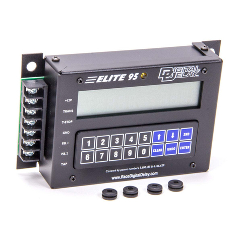
DIGITAL DELAY Mega 60 User manual

1
2036 Fillmore Street
Davenport, Ia. 52804
563-324-1046
www.racedigitaldelay.com
Mega 60 and Mega 85 w/ 4 Stage Timer
WARRANTY AND DISCLAIMER
DIGITAL DELAY INC. WARRANTS THE PRODUCTS IT
MANUFACTURES AGAINST DEFECTS IN MATERIALS AND WORKMANSHIP
FOR A PERIOD LIMITED TO 1 YEAR FROM THE DATE OF SHIPMENT,
PROVIDED THE PRODUCTS HAVE BEEN STORED, HANDLED, INSTALLED,
AND USED UNDER PROPER CONDITIONS.
The company’s liability under this limited warranty shall extend only to the
repair or replacement of a defective product, at the company’s option. DIGITAL DELAY
INC. disclaims all liability for any affirmation, promise, or representation with respect to
the products.
The customer agrees to hold DIGITAL DELAY INCORPORATED harmless
from, defend, and indemnify DIGITAL DELAY INC. against damages, claims, and
expenses arising out of subsequent sales of or use of DIGITAL DELAY INC. products, or
products containing components manufactured by DIGITAL DELAY INC. and based
upon personal injuries, deaths, property damage, lost profits, and other matters which
BUYER, its employees, or sub-contractors are or may be to any extent liable, including
without limitation, penalties imposed by the Consumer Product Safety Act (P.L. 92-573)
and liability imposed upon any person pursuant to the Magnuson-Moss Warranty Act (P.L.
93-637), as now in effect or as amended hereafter.
No warranties expressed or implied, are created with respect to the company’s
products except those expressly contained herein. The customer acknowledges the
disclaimers and limitations contained and rely on no other warranties or affirmations.

2
2036 Fillmore Street
Davenport, Ia. 52804
563-324-1046
www.racedigitaldelay.com
Mega 60 and Mega 85 w/ 4 Stage Timer Instructions
Digital Delay, Inc., the company that invented and patented the Crossover, designed and manufactured the
Mega 60 & Mega 85 w/ 4 Stage Timer simply to be the best and one of the most advanced multi-function box on
the market. The Mega 60 has one output and the Mega 85 w/4 Stage Timer has two separate outputs, they both
have two separate push-button inputs. This combination of inputs and outputs allows the Mega 60 & Mega 85 w/ 4
Stage Timer to be tailored to fit a variety of roles.
Some of the special functions of the Mega 60 & Mega 85 w/ 4 Stage Timer are, the ability to Tap either up
or down, and to select one or two push-buttons to start the delay times. The MEGA 85 w/ 4 Stage Timer also has a
throttle output that can be used as a programmable starting line enhancer or a 4-stage timer. Another special feature
includes a Driver’s Reaction Tester that allows a driver using the push buttons mounted in the vehicle to test his or
her reaction time under different circumstances. They both include scrolling keys for small number changes to be
done more rapidly.
Contents:
Warranty and Disclaimer..............................................................…. Page 1
Features, and Specifications..........................................................… Page 3
The Terminal Strip............................................................................ Page 3
The Keypad..................................................................................… Page 4
Setting Dial-Ins and Delay Times.................................................… Page 5
Setting and Displaying the Tap Up/Down.....................................… Page 5
How Late.......................................................................................… Page 5
Understanding the Drivers Reaction Tester...................................… Page 5
Setting Push-button Mode and Interrupt Time..............................… Page 6
Understanding and Connecting a By-pass push-button ...............… Page 6
Setting Stage Times......................................................................… Page 7
Setting & using Starting Line Enhancer Time (S.L.E.)...............…. Page 8
Mounting and Wiring the Unit......................................................… Page 9

3
Features and Specifications
Features:
• Microprocessor controlled timing
• Discrete I/O (input - output) construction
• Retains all numbers even with power disconnected from unit
• Large illuminated display for easy reading of information day or night
• Self-test mode on all display functions
• Dust & splash-proof backlit keypad with detent (positive feel)
• Hit the tree twice with one or two separate button
• Instant timing cycle reset
• Programmable push-button interrupt time
• Programmable Tap Up/Down feature for the delay (In pushbutton mode 1 or 3)
• Programmable Starting Line Enhancer (MEGA 85 w/ 4 Stage Timer only)
• Built-in drivers reaction tester
Specifications:
•Input Voltage Range: 10 to 18 Volts DC (16 Volt compatible)
•Operating Temperature Range: 0 to 150 degrees F.
•Push-button Current: .1 AMPS at 12 VDC
• Two Separate Inputs
•P.B.1
• P.B. 2 or Tap P.B.
The Terminal Strip
+12VDC Terminal: Connect the +12VDC terminal to a switched +12 Volt source with enough amperage
capable of driving all outputs at the same time.
Transbrake Terminal: Connect the Transbrake terminal to the Transbrake solenoid.
Connect the low side of the 2-Step here, if used.
Ground Terminal: Connect the Ground terminal to the Neg. terminal on the battery or to good steel
ground, not aluminum.
PB-1 Terminal: In Push-button Mode 3 the push-button connected to PB-1 terminal is used
to control the primary delay and the secondary delay in sequence. In Push-button Mode 1 & 2
the push-button connected to PB-1 terminal is used to control the primary delay only.
PB-2 Terminal: In Push-button Mode 2 the push-button connected to PB-2 terminal is used to control the secondary
delay only. In Push-button Mode 1 & 3 this terminal can be used for a Tap pushbutton connection.
After a Transbrake push-button has been released, every time the Tap push-button is depressed a programmable
amount of time is either added to, or subtracted from, the first delay time started until the transbrake is released.
Throttle Stop Terminal: Connect throttle stop wire to this terminal. This can be used as a
starting line enhancer or down track throttle stop controller. This is only on the MEGA 85 w/ 4 Stage Timer.

4
The Keypad
The keypad is made up of numerical and function keys that are used to control the information that is either entered
into the unit or shown on the displays. The numerical keys 0-9 are used in conjunction with the function keys to enter new
information. While the numerical keys 1-7 are used to control what information is shown on the display and the clear key is
used to clear numbers for new values, The up and down arrow keys are used for scrolling in changing number values. The
2ND key is used to switch the scrolling arrows on the screen from one side of the screen to the other. The UNDO key will add
the leading zeros on the screen. The UNDO key is used to back up one digit at a time to enter a new digit or if display 1 or 2 is
blank it will restore the original value.
Function Keys:
The function keys are used when changing either value. This allows a new setting or value to be entered using the
numerical keys.
Example:
1) Select the Dial-Ins by pressing the 1 key for Dial-Ins to be displayed, 2 key for Delay Times.
2) The screen you selected will be displayed with arrows on the side of the screen most commonly used first.
The arrows show what side of the screen is being used; to change sides press the 2ND key to move the arrow
signs from display 1 to display 2. Then press the clear key to clear that side of the screen.
3) Use the numerical keys to enter Your Dial-In, once the desired number has been entered, Press the ENTER
key and the number will be stored in memory. As the numbers are entered they will appear on the display.
4) If you want to use the scrolling arrow keys, after you have selected the correct screen you want to change,
push the 2ND key to move the arrow signs from display 1 to display 2, then push the up or down arrow to
cause the number to increase or decrease in a scrolling motion. If the arrow sign is on the side of the screen
you want, you only need to push an arrow key to scroll. To select what side of screen you want to scroll push
the 2ND key until the arrows are on the side of the screen you wish to scroll, then push the up or down arrow
until the correct number appears.
Note: If an error is made while entering, press the UNDO key to erase the last digit.
This can be repeated as many times as necessary until the display is blank.
Pressing the UNDO key one more time restores the original number.
Numerical Keys 1-7
The numerical Keys 1-7 are used to select what information is shown on the display. For example, if the Dial-Ins are
wanted and the Delay times are being displayed, the 1 key would be pressed to display the Dial-Ins. The press of the 2
key would bring up Delay times.
Displays using 1-7 Change with Clear key Change with Clear key
1 YourDial-in TheirDial-in
2
Delay1 Delay2
3
HowLate Tap(up or down)
4
P.B. mode SLE(MEGA 85 w/4 stage timer)
5(MEGA 85 w/4 stage timer) Stage 1. Stage2
6
(MEGA 85 w/4 stage timer) Stage 3 Stage4
7
DisplayTest Mode DriversReaction Tester

5
Setting Dial-In Times
To set a new Dial-In time, press the 1 key, then check the location of arrows on the screen, press the 2ND key to
move the arrows to the desired side of the screen you want to change. Press the CLEAR key and the selected display side will
go blank indicating the unit is ready to accept the new time. Enter a new time using the numerical keys. If a mistake is made
while entering the number, pressing the HELP key will erase the last digit entered. This can be repeated as many times as
necessary until the display is blank. Pressing the HELP key while the screen is blank will restore the original number. Once
the new number has been entered press the ENTER key to store in memory.
Setting Delay Times
To set a new Delay time into either Delay 1 or 2, press the 2 key. Then follow the same procedure
for entering a new number as instructed in setting new Dial-In times.
Setting and Displaying the Delay
Tap Up/Down (Sub-Add) Information
To display the Tap Up/Down information, press the 3 key. The Sub/Add information is shown to the right of the
screen. The left most digit shows the number of times the Tap Up/Down push-button was pressed. The two right hand digits
show the programmable time (0 to 99 thousands of a second) to be subtracted from or added to the delay time every time the
Tap Up/Down push-button is pressed. If a minus sign is present in front of the two digits, a subtraction from the delay time is
done, a blank indicates adding to delay times. To change the number, press the CLEAR key, and then enter the new number
(0-.099). To switch between the Sub or Add modes press the up or down arrow key, a minus sign represents tap down a blank
means tap up. The tap value goes to the thousands so 10 on the screen represent 1 hundredth in value. The Tap Up/Down will
only affect the first delay time started. The tap mode can only be used in PB mode 1 or 3, if in PB Mode 2 the tap is turned off,
shown on the screen by 4 dashes.
Understanding the How Late
To display the How Late information, press the 3 key, the How Late information is shown to the left side of the
screen. If the Transbrake is released on Delay-2 (4-Digit) the left most digit will display a “2”, if not, it will be a “1”. The
remaining digits display the How Late time. For example if the number displayed is “2.012” and your reaction time was .510
on the time slip, add the How Late time to the .510 for a total reaction time of .522 on the crossover delay.
NOTE: Both How Late and Tap Up/Down information are stored in memory until either a new number replaces the old one
or the 2ND key is pressed, this will clear both to all zeros.
Understanding the Driver’s Reaction Tester
This new feature in delay boxes allows a driver using the buttons mounted in the vehicle to test their reaction time.
This can also be used to test different kinds of buttons and locations that buttons are mounted in the vehicle for the quickest
release possible.
To select the Driver’s Reaction Tester, press the 7 key, everything on the screen will turn on, this can also be used to
check for proper screen operation. Once in Reaction Test Mode, if a push button connected to either PB. -1 or PB. -2 is
pressed and held down, the screen will go blank. After 2 seconds all eights will be shown on the screen, at which time the
driver releases the push button being held. The display will now show the amount of time from when the eights were
displayed, to when the push button was released, this is the driver’s reaction time. If the driver lets go of the button too soon,
before the display turns on, dashes will be shown on the screen to indicate a red light. If the driver does not let go of the
button within .75 seconds after the eights are displayed, the display will show reaction time of all nines to indicate a missed
light. To exit the Driver’s Reaction Test Mode press any key on the keypad. If neither P.B.-1 or P.B.-2 button is pressed; the
unit will automatically exit the Driver’s Reaction Test Mode after 30 seconds. Each time a push-button is pressed the 30-
second time period resets.
NOTE: When in the Driver’s Reaction Test Mode, the Transbrake solenoid will not be activated when a push button is
pressed.
This is to prevent any damage to the solenoid from over heating

6
Setting Push-button Mode and the
Push-button Interrupt Time
To set the Push-button Mode, press the 4 key, the Push-button Mode is shown on the left screen. The left most digit
shows “1”, “ 2” or “3” to indicate which Push-button Mode the unit is in, when in Push-button Mode 3, the P.B. 1on terminal
strip starts both the primary and secondary delays, this is done by pressing and then releasing the pushbutton on the first
desired yellow light to start delay one. Then repressing the same pushbutton and releasing on the second desired yellow light is
done to start delay 2. Care should be taken not to flinch in pushbutton mode 3 because the box will think you released, and the
car will roll out of the beams causing a red light even if you are pressing the pushbutton. When in Push-button Mode 2, one or
both push buttons can be used in any sequence, the First P.B. starts the primary and Second P.B. starts the secondary delay.
When in Push-button mode 1 the pushbutton wired to pushbutton 1 on the terminal strip will only be used to hit the tree once.
The two right digits show the programmable amount of time (00 to 99 seconds) that after the Transbrake releases, Button 1 and
Button 2 push-button inputs are disabled. To change pushbutton mode or the Interrupt Time first arrows to that screen side,
followed by pressing the arrow keys will change the pushbutton mode. To change the Push-button interrupt time press the
CLEAR key, then enter the desired number value. For example “1 10” would indicate 1 Push-button Mode with a 10 second
Interrupt Time. If no Push-button Interrupt Time is wanted enter “00”.
PUSHBUTTON MODE 1: Means one button for one hit at tree.
PUSHBUTTON MODE 2: Means two push buttons for two hits at tree.
PUSHBUTTON MODE 3: Means one pushbutton for two hits at tree.
Note: Only in pushbutton mode 1 or 3 can the push button 2 terminal be used as the tap button input.
Understanding and Connecting
a By-pass push-button
A by-pass push-button is used to engage the Transbrake solenoid without starting a timing cycle. This can be helpful
if the vehicle needs the Transbrake engaged to back up. If a by-pass push-button is desired, connect one side of a push-button
to the Transbrake terminal and the other side of the push-button to +12 Volts.
Applying 12 Volts to any of the outputs will not damage the unit.
Connecting or shorting any output terminal directly to ground will cause damage to the unit. This damage will
not be covered by the warranty. It is strongly recommended that a 15 Amp fuse be put in each of the wires coming
from the output terminals.

7
Setting Stage One and Two Times
To set a new stage time, press the 5 key to display the current stage times. Then check for the location of arrows on
the screen, press the 2ND key to move the arrows to the desired side of screen you what to change. Press the CLEAR key and
the selected display side will go blank indicating the unit is ready to accept the new time. Enter a new time using the
numerical keys. If a mistake is made while entering the number, depressing the HELP key will erase the last digit entered.
This can be repeated as many times as necessary until the display is blank. Pressing the HELP key while the screen is blank
will restore the original number. Once the new number has been entered press the ENTER key to store in memory.
To change whether the output on the terminal strip is putting out 12 volts or taking 12 volts away. Press the 5 key
for stage 1 timer, then press and hold the zero key for four seconds to change output. OFF on the left screen, ON on the
right screen, represents 12 volts off going to 12 volts on, ON OFF represents the opposite. Most air throttles need 12 volts to
close; most electric throttles need 12 volts to stay open.
Setting Stage Three and Four Times
To set a new stage 3 or 4, press the 6 key, then follow the same procedure for entering a new number
as instructed in setting new stage 1 or 2 times.
Explanation of the 4-Stage Timer
This is to help the racer understand the 4-Stage Timer when controlling a throttle stop. The 4-Stage Timer can also be
used to control other timed devices, nitrous, or timing retards.
Stage 1 represents when the throttle stop turns on. Stage 2 represents the amount of time (duration) the throttle stop
will stay on. Stage 3 represents when the throttle stop will turn on the second time during the run. Stage 4 represents the
amount of time (or duration) the throttle stays on the second time. Both Stage 1 and Stage 3 start counting from the release of
the Transbrake. Stage 2 starts counting after the amount of time set in Stage 1 is completed. Stage 4 starts counting after the
amount of time set in Stage 3 is completed.
Possible 8.90 S/C pass
Timer 1 = 1.000
Timer 2 = 2.000
Timer 3 = 08.00
Timer 4 = 00.50

8
Setting & Using the
Starting Line Enhancer
Press the 4 key, to bring up the Starting Line Enhancer on the right side of the screen. If 1 thru 5 is displayed the
Starting Line Enhancer is turned on, if a 6 displayed, the Starting Line Enhancer will be turned off. To set the Starting Line
Enhancer mode, with arrows displayed on the right side of the screen, press the arrow keys until the desired number is
displayed. If the Starting Line Enhancer is turned on, the number shown to the right screen represents the mode the Starting
Line Enhancer is in.
To change whether the output on the terminal strip is putting out 12 volts or taking 12 volts away press the 5 key for
stage 1 timer, then press the zero key to change output. OFF on left screen, ON on right screen represents, 12 volts off going to
12 volts on, ON OFF represents the opposite. Most air throttles need 12 volts to close; most electric throttles need 12 volts to
stay open.
The Starting Line Enhancer will close the throttle under two different conditions. First if the Tap push-button is
pressed before a Transbrake pushbutton is pressed (in pushbutton modes 1 and 3 only), and second when the Transbrake Push-
Button is pressed the throttle will close.
Using mode 1 will release the SLE 8 tenths of a second before the transbrake releases.
Using mode 2 will release the SLE when the transbrake releases.
Using mode 3 will release the SLE when the transbrake push-button is released.
Using mode 4 will release the SLE when the transbrake push-button is engaged. (This is mainly used in pro light racing)
Using mode 5 will release the SLE one second before the transbrake releases.
Using mode 6 will turn off the SLE.
Explanation of the Starting Line Enhancer
This is to help the racer understand how the Starting Line Enhancer works. When turned on, the Starting Line
Enhancer will close the throttle, under two different conditions, first if the Tap push-button is pressed before a Transbrake
pushbutton is pressed (in pushbutton modes 1 and 3 only) and second when the Transbrake Push Button is pressed the throttle
will close. After the throttle has been closed the Starting Line Enhancer will open the throttle at the programmed amount of
time before the Transbrake solenoid is released.
Crossover Delay = 01.35
Starting Line Enhancer = 00.40
Timer 1 = 1.000
Timer 2 = 2.000
Timer 3 = 08.00
Timer 4 = 00.50

9
Mounting the Unit
For complete viewing of the large LCD, care should be taken when mounting the unit to make sure that the display is
angled towards the driver’s eyes. Before mounting the unit, place box in the desired location and check the legibility of
the display in both day and night conditions. As shown below, the lower the box is placed below eye level, the more the
angle amount needs to increase for viewing.
Wiring the Unit
This manual suits for next models
1
Table of contents
Other DIGITAL DELAY Control Unit manuals
Popular Control Unit manuals by other brands
Advantech
Advantech SOM-5894 user manual

National Instruments
National Instruments NI 9871 Getting started guide

FLOWROX
FLOWROX SKF DN700 Installation, operation and maintenance instructions
Alpha Technologies
Alpha Technologies Cordex HP Installation and operation manual
Dometic
Dometic Q3 Operation manual
Staubli
Staubli CombiTac direqt CTD-NET Assembly instructions
