Digital Design EVOLUTION SC User manual

EVOLUTION SC
INK JET PRINTERS
INSTALLATION AND OPERATION MANUAL
digital design inc.
67 Sand Park Road
Cedar Grove, NJ 07009
(973) 857-9500
www.evolutioninkjet.com
This manual is for use in operating and maintaining the EVOLUTION SC Ink Jet
Printer. For basic start-up instructions, please refer to PART 1 Installation
Procedures.
All rights reserved. No part of this document may be reproduced, stored on a
retrieval system, or transmitted in any form, or by any means electronic,
mechanical, photocopying, recording or otherwise, without the prior permission of
Digital Design Inc.
Digital Design Inc. has a policy of continual product improvement. The Company
therefore reserves the right to modify the information contained in this manual
without prior notice.
ALL PRINT CARTRIDGES SUPPLIED BY DIGITAL DESIGN INC.
ARE FACTORY TESTED AND USE INKS SPECIALLY
FORMULATED TO PRODUCE AN OPTIMUM AND CONSISTANT
CODE. USING OTHER THAN AUTHORIZED CARTRIDGES MAY
CAUSE UNDESIRABLE RESULTS.
EVOLUTION SC IS A FULL FEATURED MODEL WITH VARIABLE
FIELD PROGRAMMING CAPABILITIES.
1 EVOLUTION SC SYSTEM MANUAL Issue 1.1 15 November 2006

TABLE OF CONTENTS
PART 1: INSTALLATION AND OPERATIONS................................. 1
INSTALLING THE EVOLUTION SC PRINTING System .................................................................. 1
MOUNTING ON PRODUCTION LINE ..................................................................................... 1
GROUNDING STRAP INSTALLATION ................................................................................... 2
INPUT POWER CONNECTION AND MODIFICATION........................................................... 2
INSTALLING THE PRINT CARTRIDGE .................................................................................. 3
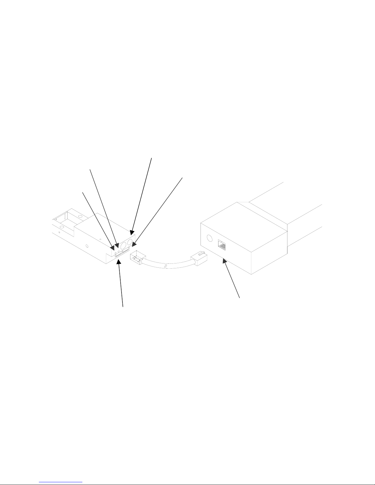
CONNECTING THE CONTROLLER TO THE PRINT HEAD...................................................... 4
CONFIGURING THE PRINTER .................................................................................................. 5
SYSTEM RESET...................................................................................................................... 5
SOFT RESET: ...................................................................................................................... 5
HARD RESET:...................................................................................................................... 6
MULTIPLE PRINT HEADS .......................................................................................................... 7
EVOLUTION SC QUICK START....................................................................................................... 8
CHANGING LANGUAGE PROMPTS ...................................................................................... 8
ENABLING PRINT MODE........................................................................................................ 8
HEAD SELECT MODE............................................................................................................. 8
ENTERING A MESSAGE......................................................................................................... 9
STORING A MESSAGE......................................................................................................... 10
LOADING A MESSAGE......................................................................................................... 11
EVOLUTION SC QUICK SETUP .................................................................................................... 12
PART 2: OPERATION PROCEDURES............................................. 1
OVERVIEW.................................................................................................................................. 1
CONTROLLER AND LCD........................................................................................................ 1
KEYPAD KEY DESCRIPTIONS........................................................................................... 2
TURNING ON THE PRINT STATION FOR THE FIRST TIME ............................................ 3
CHECKING SYSTEM INFORMATION................................................................................. 3
CHECKING LOADED FONTS.............................................................................................. 3
CHANGING SYSTEM DATE AND DAY OF WEEK CODES ............................................... 4
CHANGING SYSTEM TIME AND DATE ROLL OVER TIME .............................................. 5
PROGRAMMING ......................................................................................................................... 7
DEFINITIONS........................................................................................................................... 7
PRINTING MODE AND STOPPED “COMMAND” MODE ....................................................... 7
MENU STRUCTURE ................................................................................................................... 8
F1 MENU.................................................................................................................................. 8
F1 MENU.................................................................................................................................. 9
1 = CHARACTER SPACING: ............................................................................................... 9
2 = EXT. ENCODER:............................................................................................................ 9
3 = DATE OFFSET:............................................................................................................ 10
F2 MENU................................................................................................................................ 11
1 - DIRECTION:..................................................................................................................11
2 - PRINT INVERSE:.......................................................................................................... 11
3 – NOT AVAILABLE:......................................................................................................... 11
4 - AUTO REPEAT: ............................................................................................................ 11
F3 MENU................................................................................................................................ 12
1 – product count: ............................................................................................................... 12
2 – SHIFT CODE: ............................................................................................................... 13
3 – DATE FORMAT:........................................................................................................... 14
4 – TIME FORMAT:............................................................................................................ 16
F4 MENU................................................................................................................................ 17
1 - LANGUAGE:.................................................................................................................. 17
2 - INK SUPPLY: ................................................................................................................ 17
3 – SET UNIT I.D.:..............................................................................................................18
4 – NOT AVAILABLE:......................................................................................................... 18
SETTING PRINT DELAY AND LINE SPEED............................................................................ 19
2 EVOLUTION SC SYSTEM MANUAL Issue 1.1 15 November 2006

SETTING LINE SPEED.......................................................................................................... 19
SETTING PRINT DELAY ....................................................................................................... 20
SETTING HEAD ALIGNMENT............................................................................................... 20
INPUT, EDIT OR DELETE MESSAGES ................................................................................... 21
MESSAGE STORAGE............................................................................................................... 28
STORING A MESSAGE......................................................................................................... 28
RECALLING A STORED MESSAGE..................................................................................... 28
PART 3: MAINTENANCE PROCEDURES....................................... 1
SHORT PERIODS OF SHUTDOWN........................................................................................... 1
LONG PERIODS OF SHUTDOWN ............................................................................................. 2
PRINT CARTRIDGE MAINTENANCE......................................................................................... 3
PRINT CARRIAGE MAINTENANCE ........................................................................................... 5
EXPLODED VIEW OF THE C20991 PRINT CARRIAGE ........................................................... 5
PART 4: TROUBLESHOOTING AND REPAIRS ............................. 1
FAULTS ....................................................................................................................................... 1
PART 5: PARTS LIST AND OPTIONS............................................. 1
PART 6: COMMUNICATIONS PROTOCOL .................................... 1
DESCRIPTION............................................................................................................................. 2
DATA WORD DEFINITION...................................................................................................... 2
BAUD RATE............................................................................................................................. 2
DEFINITIONS........................................................................................................................... 2
CABLING FOR EVLINK ENVIRONMENT ............................................................................... 2
HARDWARE INTERFACE....................................................................................................... 3
PHYSICAL CONNECTIONS RS485 print carriage.................................................................. 3
PROTOCOL FORMAT:............................................................................................................ 3
EVOLUTION PRINTABLE CHARACTER SET........................................................................ 3
SOFTWARE PROTOCOL ........................................................................................................... 4
ERROR CODES .......................................................................................................................... 4
COMMANDS:............................................................................................................................... 6
PART 7: OPTION JUMPER DESCRIPTIONS................................. 23
VSEL J4 ..................................................................................................................................... 23
ENSEL J5................................................................................................................................... 23
PRSEL J6................................................................................................................................... 23
JUMPER LOCATION.................................................................................................................24
OPTION CABLING DESCRIPTIONS ........................................................................................ 25
PART 8: PRINTER SPECIFICATIONS.............................................. 1
PRINT CHARACTERISTICS ....................................................................................................... 1
CONTROLLER............................................................................................................................. 1
PRINT CARRIAGE ...................................................................................................................... 1
ENVIRONMENTAL CONDITIONS .............................................................................................. 1
GENERAL.................................................................................................................................... 1
DEFAULT SETTINGS.................................................................................................................. 2
3 EVOLUTION SC SYSTEM MANUAL Issue 1.1 15 November 2006

EVOLUTION CONTROLLER
NOTE:
THE EVOLUTION
GRAPHIC CONTROLLER
WILL CONTROL THE
EVOLUTION 1 (EV1)
EVOLUTION 2 (EV2)
EVOLUTION SC (EVSC)
THE UPPER LEFT
CORNER OF THE DISPLAY
INDICATES THE SPECIFIC
PRINTER CONNECTED TO
THE HAND HELD
CONTROLLER
PRINT HEAD
CABLE PLUG
EVOLUTION
CONTROLLER
KEYBOARD
GRAPHIC
(WSYWIG)
LCD DISPLAY
EVSC STOPPED
HD 1<- - SPEED= 120
EVOLUTION SC
EVOLUTION CODERS
4 EVOLUTION SC SYSTEM MANUAL Issue 1.1 15 November 2006

PART 1: INSTALLATION AND OPERATIONS
INSTALLING THE EVOLUTION SC PRINTING SYSTEM
Caution should be taken while installing the EVOLUTION SC printing system on your
equipment. Digital Design Inc. has taken every precaution to ensure a safe and
accurate instruction set to guide the installer through the installation process.
Follow the operational guidelines in the installation procedures.
VERIFY THAT YOUR EQUIPMENT IS IN PROPER OPERATING
CONDITION.
LOCATE A CONVENIENT POSITION ON YOUR EQUIPMENT.
EVOLUTION SC REQUIRES 4-1/2" OF SPACE ON THE
PRODUCTION LINE.
FOLLOW THE INSTALLATION PROCEDURES.
READ CAREFULLY ALL INSTALLATION PROCEDURES BEFORE
PROCEEDING.
INSTALL THE PRINTING SYSTEM ON YOUR EQUIPMENT.
THERE IS NO EXTRA HARDWARE REQUIRED OTHER THEN
THAT SUPPLIED IN THE INSTALLATION KIT.
MOUNTING ON PRODUCTION LINE
Locate the supplied mounting template
and affix in a convenient location on the
production line. Spot and drill both
mounting holes for a 5/16” bolt. NOTE:
the user may also thread the side of the
conveyer using a 5/16” tap.
Fasten the mounting bracket to the
conveyer using the supplied mounting
hardware and ensuring that the supplied
ground strap is located securely beneath
either of the two mounting bolts, and that
conductivity to earth ground is less than 1 ohm. This ensures a proper path for
static discharge, should the need arise.
1 EVOLUTION SC SYSTEM MANUAL Issue 1.1 15 November 2006

GROUNDING STRAP INSTALLATION
INSTALL STRAP
UNDER 5/16”
SCREW. E
CONDUCTIVITY TO
EARTH GROUND IS
LESS THAN 1 OHM
NSURE
INPUT POWER CONNECTION AND MODIFICATION
Insert the power plug to the available power source. The supplied power supply
will is universal and will auto detect 100/240 VAC 50-60hZ.
No other adjustments are necessary.
2 EVOLUTION SC SYSTEM MANUAL Issue 1.1 15 November 2006

INSTALLING THE PRINT CARTRIDGE
Remove the protective film from the face of the print head and retain the film.
This protective film may be re-applied to store partially used cartridges. If it is
necessary to remove the print head and store for a long period of time, it is best
to re-apply the plastic film, and place the cartridge in a closeable plastic bag.
The print cartridge is installed into the print head by inserting at a slight angle and
depressing the rear of the cartridge until it snaps into place. To remove the
cartridge gently lift the rear tab on the
NOTE: EACH PRINT CARTRIDGE HAS BEEN TESTED
AT THE FACTORY AND CONTAINS SPECIALLY
FORMULATED INKS. USING ANY OTHER PRINT
CARTRIDGE WILL HAVE UNDESIRABLE RESULTS.
PRINTHEAD SEATED CORRECTLY
INSERT PRINTHEAD INTO
HOLDER FROM THIS ANGLE
AND PRESS DOWNWARD UNTIL
SEATED
3 EVOLUTION SC SYSTEM MANUAL Issue 1.1 15 November 2006

CONNECTING THE CONTROLLER TO THE PRINT HEAD
Connect the Controller to the print carriage using the supplied 3 FT (.9 mm)
interconnect cable C21008-3 supplied with the Printing System. The cable is a
standard RJ50 (10 conductor). Longer cables are available as required.
Connect either end of the cable to the Carriage Assembly and securely lock in
place. NOTE: THE CONNECTOR MUST BE PLUGGED INTO THE INPUT RJ50
CONNECTOR LOCATED BELOW THE POWER CONNECTOR AND MARKED
WITH AN ARROW POINTING TO THE CONNECTOR. A click will be heard
when the connector is in the appropriate position. Connect the free end to the
Controller Assembly and ensure connector is securely seated.
RED PRINT
ENABLE LED
GREEN
CYCLE LED
PRINT CARRIAGE RJ50
OUTPUT CONNECTOR
POWER INPUT
+12VDC @1.5A
CONTROLLER RJ50
CONNECTOR
PRINT CARRIAGE RJ50
INPUT CONNECTOR
CAUTION:
NOTE ORIENTATION OF THE CONNECTORS. DO NOT FORCE
CONNECTORS INTO POSITION SECURELY LATCH (CLICK) INTO
POSITION.
CONTROLLER MUST PLUG INTO THE PRINT CARRIAGE RJ50 INPUT
CONNECTOR FOR PROPER OPERATION. THE PRINT CARRIAGE RJ50
OUTPUT CONNECTOR IS USED EITHER FOR CONNECTION TO THE NEXT
PRINTER ON A NETWORK OR FOR EXTERNAL PRODUCT OR EXTERNAL
ENCODER INPUT.
THE POWER INPUT CONNECTOR MUST BE SECURELY INSERTED INTO
THE PRINT CARRIAGE. UPON PROPER INSERTION BOTH THE RED AND
GREEN LED’S WILL FLASH INDICATING PROPER CONNECTION.
4 EVOLUTION SC SYSTEM MANUAL Issue 1.1 15 November 2006

CONFIGURING THE PRINTER
To verify the current operating software press the STOP PRINT
key.
Press the V key
CONTROLLER 1.06
EVSC 1.03_++++
PRINTER SN XXXXXX
ANY KEY TO EXIT
The fist line indicates the version of the controller software
The second line is the software of the printer
The third line indicates the serial number of the printer
SYSTEM RESET
SOFT RESET:
A Soft Reset may be performed by first removing the power from the system and
while holding the R key depressed re-apply the power. Refer to the section on
Soft Reset.
ERASE STORED
MESSAGES
YES OR NO Y/N
Pressing the R key while applying power to the
unit will display the reset command mode
CAUTION: A response of Y will delete all stored
messages.
RESET PRINT HEAD
YES OR NO Y/N
The next screen to appear prompts the user to
determine if a print head is to be restored to its
default value.
CAUTION: ALL PRINT HEADS CONNECTED
TO THE CONTROLLER WILL BE RESET TO
FACTORY DEFAULT CONDITIONS. THIS
INCLUDES RESETING EACH UNIT ADDRESS
TO 1. TO PREVENT THIS REMOVE ALL
INTERCONNECTED PRINT HEADS EXCEPT
FOR THE UNIT TO BE RESET FROM THE
DATA LINK.
ALL HEADS
WILL BE RESET
CONTINUE = X KEY
ANY OTHER EXITS
5 EVOLUTION SC SYSTEM MANUAL Issue 1.1 15 November 2006

HARD RESET:
In the event it is necessary to perform a hard reset, disconnect the power cable,
insert a standard paperclip into the hole located on the top of the cabinet, and
while holding the paper clip in place (a light click will be felt) re-apply the power
connector.
This operation will reset the print carriage assembly to the factory default settings
and clear any current message.
Note: upgrading the system to a newer version of software will automatically
perform this operation.
6 EVOLUTION SC SYSTEM MANUAL Issue 1.1 15 November 2006

MULTIPLE PRINT HEADS
EVOLUTION printing systems have the ability to reside on a network. The network
may contain from 1 to 32 print carriages connected via RJ50 cables. These
cables are available in varying lengths depending on the application.
Each mounting bracket can support up to 4 print carriages and would typically
interconnect with a 6” RJ50 data cable.
NOTE: Special care must be taken to connect the output of the first print carriage
to the input of the next print carriage.
When connecting multiple print carriages place no more than 2 stations on a side
of the mounting bracket as shown.
PRINT CARRIAGE
ADDRESS 1
TO
CONTROLLER
OR COMPUTER
DATA LINK
PRINT CARRIAGE
ADDRESS 4
7 EVOLUTION SC SYSTEM MANUAL Issue 1.1 15 November 2006

EVOLUTION SC QUICK START
Connect the printer carriage to the appropriate
power source.
EVSC STOPPED
HD 1< - - SPEED=120
EVOLUTION SC
Connect the controller to the carriage assembly.
The controller derives power from the carriage.
On startup the LCD will display as pictured.
CHANGING LANGUAGE PROMPTS
< - - SELECT - - >
ENGLISH Press the F4 key and select for
LANGUAGE. Use the keys to select the
desired language and press the to select the
language.
ENABLING PRINT MODE
EVSC PRINTING
HD 1< - - SPEED=120
EVOLUTION SC
Press the GREEN PRINT key to start printing
HEAD SELECT MODE
EVSC STOPPED
HD 1< - - SPEED=120
EVOLUTION SC
The hand held controller can program up to 32 print
carriages on an RS485 data link. The factory default
sets each print carriage to ADDRESS 1. Selection
of another print head other than ADDRESS 1, press
the key. Use the keys to select the
alternate print carriage number and press the
key. The print carriage whose address was selected
will respond with the current message and
appropriate parameters.
< - - SELECT - - >
WHICH HEAD = 1
EVOLUTION SC
As an added convenience using the will auto
scan to find the next available head connected to
the environment
NO RESPONSE
ANY KEY TO EXIT
Accessing an address not associated with any print
carriage will result in a no response message.
8 EVOLUTION SC SYSTEM MANUAL Issue 1.1 15 November 2006

ENTERING A MESSAGE
Press the GREEN PRINT key
EVSC STOPPED
HD 1< - - - SPEED=120
EVOLUTION SC
The LCD display will change from PRINTING to
STOPPED.
MESSAGE ENTRY
- - - - FONT – 1 S12
EVOLUTION SC
Press the GREEN EDIT key
MESSAGE ENTRY
- - - - FONT - 1 S12
Press the BLUE F3 key to delete the entire
message
MESSAGE ENTRY
- - - - FONT – 1 S 12
EXP 12/10/04
Press the BLUE FONT key to select the
desired font size and enter the text EXP 12/10/04
Press the ENTER key to end the MESSAGE
EDIT mode
Press the GREEN print enable key to enter
the print mode
EVSC PRINTING
HD 1< - - - SPEED=120
EXP 12/10/04
9 EVOLUTION SC SYSTEM MANUAL Issue 1.1 15 November 2006

STORING A MESSAGE
EVSC STOPPED
HD 1< - - - SPEED=120
EXP 12/10/04
Press the GREEN STOP PRINT KEY
Note: There are a maximum of 100
messages stored.
MESSAGE # 1 EVSC
Press the RED MESSAGE STORE key
The LCD display will display the message storage
screen
Use the or to select the desired storage
location
MESSAGE # 1 EVSC
MESSAGE STORED
EXP 12/10/04
Press the RED MESSAGE STORE KEY a
second time and the current message appears in
the selected location and is stored.
EVSC STOPPED
HD 1< - - - SPEED=120
EXP 12/10/04
Press the ENTER key to return to the
command prompt.
10 EVOLUTION SC SYSTEM MANUAL Issue 1.1 15 November 2006

LOADING A MESSAGE
Press the GREEN STOP PRINT KEY
EVSC STOPPED
HD 1< - - - SPEED=120
EVOLUTION SC
Note: There are a maximum of 100
messages stored.
Press the RED MESSAGE STORE key
NOTE: The top line indicates that this message
is for an EVSC – Evolution Small Character
printer.
MESSAGE # 1 EVSC
PLEASE WAIT
MESSAGE # 1 EVSC
EXP 12/10/04
Use the or keys to select the desired
message
EVSC STOPPED
HD 1< - - - SPEED=120
EXP 12/10/04
Press the ENTER key
EVSC PRINTING
HD 1< - - - SPEED=120
EXP 12/10/04
Press the GREEN print enable key to enter
the print mode
11 EVOLUTION SC SYSTEM MANUAL Issue 1.1 15 November 2006

EVOLUTION SC QUICK SETUP
Install a new cartridge. Press the following keys in order:
To reset the ink level detector press
REMAINING INK
100 %
C NEW CARTRIDGE
OTHER KEY EXIT
Each time a new print cartridge is installed the system automatically profiles the
correct operating parameters for the new cartridge. These parameters set the
required voltage and on time to produce consistent results without user
intervention..
NOTE: USING OTHER THAN AUTHORIZED CARTRIDGES MAY CAUSE
UNDESIRABLE RESULTS.
Press the GREEN print enable key to enter the print mode
To set the LINE SPEED, press to put the system in the Printing mode.
Set character width by
To set the PRINT DELAY press: to put the system in the Printing mode.
Set print delay by
. NOTE: Each increment or decrement changes the delay by the pre-defined
amount.
You may continue to experiment with line speed and print delay until the desired
code registration on the product is achieved.
12 EVOLUTION SC SYSTEM MANUAL Issue 1.1 15 November 2006

PART 2: OPERATION PROCEDURES
OVERVIEW
CONTROLLER AND LCD
The keypad on the print
station, pictured here,
contains 64 keys. The LCD
will display various messages
to assist in programming on
the upper half of the display.
The lower half of the display
will show up to two lines of
the entered print message.
EVOLUTION CODERS
P h RED MESSAGE STORE
STOPPED
HD 1 - ->SPEED= 120
EVOLUTION SC
The system operates is 3
basic modes. They are: Print
Mode, Command Mode, and
Message Entry Mode. In
Print Mode the majority of the
keys on the keypad are
disabled to avoid inadvertent
changes. When in Print Mode
the Top line of the LCD will
display PRINTING.
The Command Mode is used
to change the functions of the
printer. When in the
Command Mode the display
will show STOPPED on the
top line. The Message Entry
Mode is used to create or
modify printable codes, when
in this mode the top line of the
display will show MESSAGE
ENTRY.
The 4 keys on the top row are
the function keys F1 through
F4. They each consist of
submenus for modifying
various printer functions.
Their specific menus are
detailed later in this section.
The next two rows of keys
with icon legends directly
control specific parameters of
the printer as follows.
1 EVOLUTION SC SYSTEM MANUAL Issue 1.1 15 November 2006

KEYPAD KEY DESCRIPTIONS
.
This is the manual cycle key. When in the Stopped mode, pressing this
key causes the printer to print one code
This is the Print key. Use it to place the unit in the Print mode
This is the Purge key. Use it to purge ink for maintenance purposes. The
unit must be in the Command mode to use this key.
This is the Head Select key. Use it to select the address of the head to be
communicated with. In edit mode it enters the DAY of WEEK
Use this arrow to decrease values, and use it to move the cursor in the
message line while editing the message.
Use this arrow to increase values and use it to move the cursor in the
message line while editing the message.
Use this arrow to move the cursor between the message lines while in
Edit mode and building a message.
Use this arrow to move the cursor between the message lines while in
Edit mode and building a message.
This key is the Message Storage key. Use it to store and to recall
individual codes.
This is the Delete key. Use it to backspace to delete a character when
mistyped as well as to exit from certain menus.
This is the Message Entry key. Use this key to enter the Message Entry
mode, to input a code or to edit a code.
This is the Date key. Use this key to enter the Date in Message Entry
Mode. Change Date in STOPPED mode.
This is the Time key. Use this key to enter the Time in Message Entry
Mode. Change Time in STOPPED mode.
This is the Sequence Number key. Use this key to enter the Sequence
Number in Message Entry Mode. Command mode sets count parameters
This is the Enter or Return key. When pressed, the unit will accept input
and exit certain menus.
This is the Print Delay key.
In Message Entry Mode this is the DATE OFFSET FUNCTION
This is the Line Speed key.
In Message Entry Mode this is the SHIFT CODE FUNCTION
This key selects the Font size in the EDIT mode.
In the COMMAND mode pressing this key displays the current fonts
loaded in the print head.
S1 Pressing this key while in the Message Entry mode accesses special
characters
S2 This key is reserved for special customer Logos
2 EVOLUTION SC SYSTEM MANUAL Issue 1.1 15 November 2006

TURNING ON THE PRINT STATION FOR THE FIRST TIME
To turn the print station on insert the power jack
into the DC power connector.
There is no on/off switch.
The first time the print station is turned on, as
received from the factory, the LCD will look like
the illustration on the left. Each line gives
important information regarding the system:
EVSC STOPPED
HD1- - >SPEED=120
EVOLUTION SC
The Top line indicates the PRINT SYSTEM TYPE and the operating mode of the
unit: “STOPPED” when in Command mode, “ PRINTING” when in Print mode,
and “MESSAGE ENTRY when in message entry.
The 2nd line shows the print head currently selected, the direction of travel for the
product and the programmed SPEED.
The lower half two lines of the display shows the message entered for printing.
This may represent one or two lines of code.
CHECKING SYSTEM INFORMATION
Verify system information by pressing the V key
on the hand held controller keyboard. The LCD
screen will display the software, firmware, serial
number and options enabled. Enabled options
are indicated on the second line as a series of +
characters where the first + indicates option
pack 1, the second + indicates option pack 1.5 and the last + indicates option
pack 2.
CONTROLLER 1.06
EVSC 1.03_++++
PRINTER SN284955
ANY KEY TO EXIT
CHECKING LOADED FONTS
Press the FONT key in the COMMAND
mode to check what fonts are currently loaded
in the print head.
NOTE: The Evolution small character has 5
font styles:
12x9 1 line of text
EVSC ACTIVE FONTS
2 LINE DDI S_5
1 LINE DDI S_7
1 LINE DDI B_7
1 LINE DDI S_12
1 LINE DDI B_12
ANY KEY TO EXIT
12x9 bold 1 line of text
7x5 1 line of text
7x5 bold 1 line of text
5x5 2 lines of text
3 EVOLUTION SC SYSTEM MANUAL Issue 1.1 15 November 2006

CHANGING SYSTEM DATE AND DAY OF WEEK CODES
PRESENT SETTING
ANY CHANGES Y/N
01/04/00
When the unit is in the STOPPED mode
pressing the DATE key allows the user to
change the system date. If there are no
changes press the N key to return to the
STOPPED mode.
Press the Y key to change the date.
PRESENT SETTING
ANY CHANGES Y/N
01/04/00
ENTER MONTH-
The system will prompt the user first for the
Month (enter 2 digits), then the Day (2 digits)
and finally the year (2 digits).
PRESENT SETTING
ANY CHANGES Y/N
01/04/00
ENTER DAY-
PRESENT SETTING
ANY CHANGES Y/N
01/04/00
ENTER YEAR-
After the date is entered the system requests
the actual date day of week. This parameter is
usually set to 1 for Sunday, 2 for Monday etc.
< - - SELECT - - >
DAY OF WEEK- 1
DAY FORMAT
1= NUMERIC
2= LETTERS
The day of the week can be entered into a
message as either a number 1-7 or as a letter
A-G. The day of the week is entered into a
message by pressing the key.
After the data is entered the system displays
the currently entered date and pressing the N
key returns the user to the STOPPED mode,
or press Y to the correct the date.
PRESENT SETTING
ANY CHANGES Y/N
04/23/05
4 EVOLUTION SC SYSTEM MANUAL Issue 1.1 15 November 2006
Table of contents
Other Digital Design Printer manuals