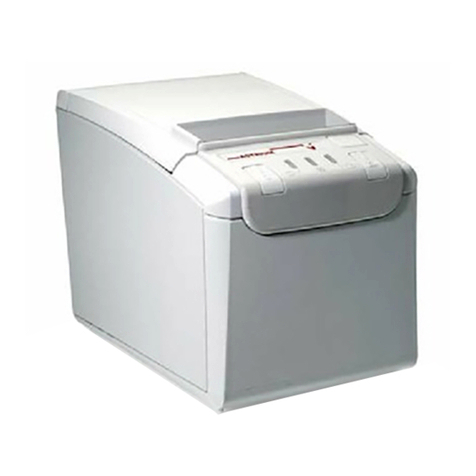
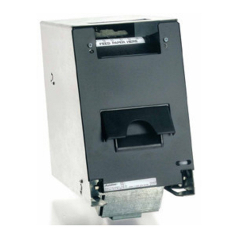
Axiohm A721 User manual

A721 Multifunction Printer:
Setup Guide
7221-D110

A721 Multifunction Printer:
Setup Guide
7221-D110
Axiohm IPB
Ithaca, New York

ii August 1998
Disclaimer
Information in this document is subject to change without notice. Therefore,
before using this document, consult your Axiohm sales representative for
information that is applicable and current. Axiohm reserves the right to improve
products as new technology, components, software, and firmware become
available.
No part of this document may be reproduced or transmitted in any form or by
any means, electronic or mechanical, for any purpose without the express written
permission of Axiohm.
Copyright
Copyright © 1997, 1998 by AXIOHM
Ithaca, New York USA
All rights reserved
Printed in USA
Confidential, Unpublished
Property of AXIOHM
Trademarks
AXIOHM is the registered trademark of AXIOHM. Other trademarks and
registered trademarks are the property of their respective holders.

A721 Setup Guide Contents
August 1998 iii
Important Information to the User
In order to ensure compliance with the Product Safety, FCC and CE marking
requirements, you must use the power supply, power cord, and interface cable
which were shipped with this product or which meet the following parameters:
Power Supply
UL Listed (QQGQ), Class 2 power supply with SELV (Secondary Extra Low
Voltage), non-energy hazard output, limited energy source, input rated 100-240
Vac, 1.5/0.8 A, 50/60 Hz, output rated 24 Vdc, 2.3 A.
Use of this product with a power supply other than the Axiohm power supply
will require you to test this power supply and Axiohm printer for FCC and CE
mark certification.
Interface Cable
A shielded (360 degree) interface cable must be used with this product. The
shield must be connected to the frame or earth ground connection or earth
ground reference at EACH end of the cable.
Use of a cable other than described here will require that you test this cable with
the Axiohm printer and your system for FCC and CE mark certification.
Power Cord
A UL listed, detachable power cord must be used for this product. For
applications where the power supply module may be mounted on the floor, a
power cord with Type SJT marking must be used. For applications outside the
US, power cords which meet the particular country’s certification and
application requirements should be used.
Use of a power cord other than described here may result in a violation of safety
certifications which are in force in the country of use.
Industry Canada (IC)
Radio Frequency Interference Statement
This Class A digital apparatus meets all requirements of the Canadian
Interference-Causing Equipment Regulations.
Cet appareil numérique de la classe A respecte toutes les exigences du
Règlement sur le matériel brouilleur du Canada.

iv August 1998
Federal Communications Commission (FCC)
Radio Frequency Interference Statement
Warning
Changes or modifications to this unit not expressly approved by the party
responsible for compliance could void the user’s authority to operate the
equipment.
Note
This equipment has been tested and found to comply with the limits for a Class
A digital device, pursuant to Part 15 of the FCC Rules. These limits are designed
to provide reasonable protection against harmful interference when the
equipment is operated in a commercial environment. This equipment generates,
uses, and can radiate radio frequency energy and, if not installed and used in
accordance with the instruction manual, may cause harmful interference to radio
communications. Operation of this equipment in a residential area is likely to
cause harmful interference in which case the user will be required to correct the
interference at his own expense.
Communication Cables
Shielded communication cables must be used with this unit to ensure compliance
with the Class A FCC limits.
Information to User
This equipment must be installed and used in strict accordance with the
manufacturer's instructions. However, there is no guarantee that interference to
radio communications will not occur in a particular commercial installation. If
this equipment does cause interference, which can be determined by turning the
equipment off and on, the user is encouraged to contact Axiohm immediately.
The Axiohm company is not responsible for any radio or television interference
caused by unauthorized modification of this equipment or the substitution or
attachment of connecting cables and equipment other than those specified by
Axiohm. The correction of interferences caused by such unauthorized
modification, substitution or attachment will be the responsibility of the user.

A721 Setup Guide Contents
August 1998 v
Contents
Contents v
Chapter 1: Unpacking the Printer 1
What Is in the Box? 1
Removing the Packing Material 1
Repacking the Printer 2
Chapter 2: Setting Up the Printer 3
Setting Switches 4
Setting RS-232C Communication Parameters 5
Setting Parallel Communication Parameters 6
Switch Entry Mode 7
Connecting the Cables 19
Loading Paper 20
Loading Receipt Paper 20
Loading Receipt/Journal Paper 22
Installing the Ribbon Cassette 24
Testing the Printer 25
Running the Print Test 25
Sample of Test Printout 26
Adjusting the Printhead Gap 27

Contents A721 Setup Guide
vi August 1988

A721 Setup Guide Chapter 1: Unpacking the Printer
August 1998 1
Chapter 1: Unpacking the Printer
Follow these instructions to unpack the printer. Save all the packing materials for
re-packing the printer if needed.
What Is in the Box?
The following items are packed in the shipping box:
•Printer enclosed in a plastic bag and foam pack
•Test printout (inside receipt bucket)
•Foam restraint for the slip table
•Foam restraint for the carriage (under front cover)
•Power supply with cable connecting to printer with strain relief and
power supply cord connecting to power outlet (in box—only if ordered
with the printer)
•Receipt paper roll (if ordered) and ribbon cassette (in box)
Caution: Do not remove the mylar shield on the ribbon cassette or the
ribbon cassette will be ruined. The shield protects against smudging.
•Installation report card
Removing the Packing Material
1. When the printer is removed from the packing materials, open the rear
cover by pulling up on the front left corner.
2. Remove the test printout and installation report card from inside the
receipt bucket.
3. Remove the foam restraint for the slip table between the slip table and
cabinet.
4. Open the cassette cover and remove the foam restraint from the
carriage.

Chapter 1: Unpacking the Printer A721 Setup Guide
August 1998
2
5. Remove the ribbon cassette, receipt roll, power supply, and cables from
the box.
6. Save all packing materials for future storing, moving, or shipping.
Caution: Be sure that both of the foam restraints have been removed before
operating the printer.
Cassette
Cover
Foam
Restraint
Foam
Carriage
Restraint
Rear
Cover 1
Lower
Cantilever
Cover
Slip
Table 3
4Carriage
Lower Cantilever
Cover
(Cassette Cover
removed for clarity)
Repacking the Printer
1. Open the cassette cover and remove the ribbon cassette.
2. Move the carriage to the right and place the foam restraint for the
carriage between the left side of the printer and the carriage.
3. Place the foam restraint for the slip table between the slip table and the
cabinet.
4. Place the printer in the plastic bag and foam pack.
5. Place the packed printer in the box and secure with packing tape.
6. Contact your Axiohm authorized service organization for information
on where to send the printer.
Be prepared to answer questions concerning shipping and billing.

A721 Setup Guide Chapter 2: Setting Up the Printer
August 1998 3
Chapter 2: Setting Up the Printer
The A721 printer may be placed on a level surface on or near the host computer.
Make sure there is enough room to open the cover to change the paper and
ribbon cassette. The illustration shows the actual dimensions of the printer, but
leave several inches around the printer for connecting and accessing the cables.
This printer was designed to operate in the environment outlined in the
“Environmental Requirements” section of Appendix A in the A721
Multifunction Printer Owner’s Guide. Operation outside these ranges as defined
may lead to degradation of the printer functionality and reliability, and may
result in higher than specified service call rates. In environments which contain a
high level of contaminants, dirt, airborne debris or particles, preventative
maintenance will be required.
Note: The MICR check reader feature has been factory adjusted for a normal
operating environment with a host computer. However, additional devices, such
as CRT monitors or large metal surfaces near the printer, can affect the printer's
magnetic field, causing intermittent reading errors when the MICR check reader
is in operation.
This condition can be easily diagnosed by checking the noise level of the MICR
check reader. See chapter 2 in the A721 Multifunction Printer Owner’s Guide
for more information.
165 mm
(6.5 in.) 259 mm
(10.2 in.)
165 mm
(6.5 in.)
w/Journal 147.3 mm
(5.8 in.)
Receipt Only

Chapter 2: Setting Up the Printer A721 Setup Guide
August 1998
4
Setting Switches
Off
Switch 1 is shown
in the ON position
On
DIP Switch
12345678
The DIP switches are located at the rear of the printer as shown in the
illustration. They are used to set the communication parameters as outlined in the
following table. These parameters must match those of the host computer in
order for the host computer and the printer to communicate.
Note: The switches are also used for setting other functions and tests. Be careful
when setting the switches that you do not accidentally change the settings for the
other functions. For more information, see “Level 1 Diagnostics” in the A721
Multifunction Printer Owner’s Guide.

A721 Setup Guide Chapter 2: Setting Up the Printer
August 1998 5
Setting RS-232C Communication Parameters
The communication parameters must match those of the host computer in order
for the host computer and the printer to communicate.
Use a straightened paper clip or other pointed object to set the switches.
1. Turn the printer to the back to access the DIP switches.
2. Set the switches to the settings you want, using the options in the
following table.
Caution: Do not set switch 1 to On. Setting switch 1 to On puts the printer in
the Level 1 diagnostics (setup mode) where other functions and tests can be
changed. Set switch 1 to Off when setting switches for the communication
settings. This puts the printer in the Online mode so it can communicate with the
host computer.
DIP Switch Settings for RS-232C Parameters
Switch Settings Description
1OFF
ON On-line Mode. Use to set RS-232C options (default)
Offline. Level 1 Diagnostics (setup mode)
2OFF
ON DTR/DSR Protocol (default)
XON/XOFF Protocol
3OFF
ON Without Parity (default)
With Parity
4* OFF
ON Odd Parity
Even Parity
5, 6 5
OFF
ON
OFF
ON
6
OFF
OFF
ON
ON
19,200 Baud
9600 Baud (default)
4800 Baud
1200 Baud
*Switch 4 is not used if the parity is disabled (switch 3 OFF). Switches 7, 8 are
not used.

Chapter 2: Setting Up the Printer A721 Setup Guide
August 1998
6
Setting Parallel Communication Parameters
Use a straightened paper clip or other pointed object to set the switches.
1. Set all of the DIP switches to OFF to put the printer online and ready
for parallel communication.
Caution: Do not set switch 1 to On. Setting switch 1 to On puts the printer in
the Level 1 diagnostics (setup mode) where other functions and tests can be
changed. Set switch 1 to Off when setting switches for the communication
settings. This puts the printer in the Online mode so it can communicate with the
host computer.
Switch1Switch2Switch3Switch4Switch5Switch6Switch7Switch8
OFF OFF OFF OFF OFF OFF OFF OFF

A721 Setup Guide Chapter 2: Setting Up the Printer
August 1998 7
Switch Entry Mode
Use Switch Entry mode to set the printer emulation or the internal switch pack
values in NVRAM.
Note: For an alternate method to set the emulation and switch settings, see
“Chapter 10: Flash Download Commands” in the A721 Multifunction Printer
Owner’s Guide.
The A721 printer can emulate the following printers and emulations:
•Epson ESC/POS (370/5) printer
Note: This emulation is included in the A721 ESC/POS commands.
•Ithaca Peripherals Proprinter emulation
•Axiohm 5021 printer
•DH 4700 printer
The A721 printer has one set of DIP switches, while some of the emulated
printers have two or more sets. You can enter values for the extra switch packs
into “internal switch packs” stored in NVRAM.
All procedures completed in Switch Entry mode include two steps:
•First, tell the printer what you want to do—either choose an emulation
or choose an internal switch pack value. (For example, choose the
Ithaca Peripherals Proprinter emulation or internal switch pack 2.)
•Second, enter the value for the operation—either the specific printer
emulation or the values for the internal switch pack.
Both steps are completed by setting the DIP switches. During the first step, the
Slip In LED is on. During the second step, the Slip In LED is off.
Once you’ve finished setting options in Switch Entry mode, turn off the printer
and set the DIP switches back to the settings for the appropriate communication
protocol. The options you set in Switch Entry mode are stored in “internal
switch packs” in NVRAM until you change them.
Use the print test to print the name of the emulation which is currently active and
the settings of the NVRAM switch packs. See “Running the Print Test” later in
this chapter for information about running the test.

Chapter 2: Setting Up the Printer A721 Setup Guide
August 1998
8
Choose a Printer Emulation
Caution: The DIP switches are set at the factory to predetermined settings.
Change the settings carefully to avoid changing other functions. Run the print
test to see what emulation the printer is set for. For more information, see
“Running the Print Test” later in this chapter.
1. Turn the printer off.
2. Turn the printer to the back to access the DIP switches and write down
the current switch settings.
3. To put the printer into Switch Entry mode, set the DIP switches to the
following settings:
Switch
12345678
ON ON OFF OFF OFF OFF OFF OFF
4. Turn the printer back on.
The printer is now in Switch Entry Mode as indicated by the green
Online LED and the red Paper Status LED flashing. The green Slip In
LED may be on or off, depending on your input at the time.
5. To indicate to the printer that you are choosing a printer emulation, set
all of the DIP switches to Off.
6. Press the Paper Feed button.
The green Slip In LED turns off.
7. Set the DIP switches to the settings for the printer you want to emulate:
See the table on the next page.

A721 Setup Guide Chapter 2: Setting Up the Printer
August 1998 9
Switch
Emulation 12345678
A721
ESC/POS* OFF OFF OFF OFF OFF OFF OFF OFF
IPI Proprinter
Emulation OFF OFF OFF OFF OFF OFF ON OFF
Axiohm 5021 OFF OFF OFF OFF OFF OFF OFF ON
DH 4700 OFF OFF OFF OFF OFF OFF ON ON
*The A721 ESC/POS includes Epson ESC/POS (in order to emulate the
Epson 370/5 printer).
8. Press the Paper Feed button.
The green Slip In LED turns on. The printer emulation you selected is
stored in NVRAM.
9. Turn the printer off and reset the DIP switches to what they were when
you started.
For normal operation settings, see “Setting RS-232C Communication
Parameters” earlier in this chapter.
10. Turn the printer back on.
Use the print test to print the name of the emulation which is currently active and
the settings of the NVRAM switch packs. See “Running the Print Test” later in
this chapter for information about running the tests.
Set Internal Switch Pack Values in NVRAM
Once you’ve chosen the emulation (in the previous section), you can specify
various printer functions by setting the switches on “internal switch packs.”
Caution: The DIP switches are set at the factory to predetermined settings.
Change the settings carefully to avoid changing other functions.
1. Turn the printer off.
2. Turn the printer to the back to access the DIP switches and write down
the current switch settings.

Chapter 2: Setting Up the Printer A721 Setup Guide
August 1998
10
3. To put the printer into Switch Entry mode, set the DIP switches to the
following settings:
Switch
12345678
ON ON OFF OFF OFF OFF OFF OFF
4. Turn the printer back on.
The printer is now in Switch Entry Mode as indicated by the green
Online LED and the red Paper Status LED flashing. The green Slip In
LED may be on or off, depending on your input at the time.
5. Set the DIP switches according to the following table to select the
internal switch pack you want to use.
See the tables in the following four sections to determine the switch
pack you need for the emulation you have already chosen:
•“A721 ESC/POS Internal Switch Pack Settings”
•“Ithaca Peripherals Proprinter Internal Switch Pack Settings”
•“Axiohm 5021 Internal Switch Pack Settings”
•“DH 4700 Internal Switch Pack Settings”
Switch
SwitchPack12345678
1 OFF OFF OFF OFF OFF OFF OFF ON
2 OFF OFF OFF OFF OFF OFF ON OFF
3 OFF OFF OFF OFF OFF OFF ON ON
4 OFF OFF OFF OFF OFF ON OFF OFF
6. Press the Paper Feed button.
The green Slip In LED turns off.
7. Set the DIP switches to the settings on the switch pack and for the
emulation you have already chosen.
Use the tables in the following four sections (as listed under number
five above).

A721 Setup Guide Chapter 2: Setting Up the Printer
August 1998 11
8. Press the Paper Feed button.
The green Slip In LED turns on. The internal switch pack and switch
settings you chose are stored in NVRAM.
You can print out a listing of the settings you’ve chosen using the
Diagnostic Print Tests. For more information, see “Running the Print
Test” later in this chapter.
9. Turn the printer off and reset the DIP switches to what they were when
you started.
For normal operation settings, see “Setting RS-232C Communication
Parameters” earlier in this chapter.
10. Turn the printer back on.
Repeat this procedure to select settings on a different switch pack.
Use the print test to print the name of the emulation which is currently active and
the settings of the NVRAM switch packs. See “Running the Print Test” later in
this chapter for information about running the tests.
A721 ESC/POS Internal Switch Pack Settings (Includes Epson ESC/POS)
A721 ESC/POS: Internal Switch Pack 1
Switch Settings Description
1OFF
ON Print “?” for data error.
Ignore data error.
2OFF
ON 4K byte communication data buffer.
40 byte data buffer.
3-8 Unused.
A721 ESC/POS: Internal Switch Pack 2
Switch Settings Description
1OFF
ON No display module connected (default).
No display module connected (same as ON).
2 Unused.
3OFF
ON Busy on buffer full or offline (default).
Busy on buffer full.
4-8 Unused.

Chapter 2: Setting Up the Printer A721 Setup Guide
August 1998
12
A721 ESC/POS: Internal Switch Pack 3, Switch 1
Switch Settings Description
1OFF
ON
Set default Epson line spacing to 7.2 lines per inch
(paper saving mode).
Set default line spacing to 6 lines per inch.
A721 ESC/POS: Internal Switch Pack 3, Switches 2 and 3
Switch 2 Switch
3Description
OFF OFF Epson 40/33 character print zone (2.506 inches wide).
OFF ON Epson 42/35 character print zone (2.506 inches wide).
ON OFF Axiohm 42/35 character print zone (3.024 inches wide).
ON ON Axiohm 51/42 character print zone (3.024 inches wide).
A721 ESC/POS: Internal Switch Pack 3, Switches 4 and 5
Switch Settings Description
4OFF
ON
Set the standard mode slip/validation right margin to 0.53
inches (Epson Compatible). This only applies if switch 2
is OFF (2.506 inch print zone).
Center the print zone for standard mode. Right margin set
to 0.113 for 3.024 inch print zone or to 0.372 for 2.506
inch print zone.
5OFF
ON
Set the page mode slip/validation right margin to
0.53 inches (Epson compatible).
Center the print zone for page mode. Right margin set to
0.372 inches.

A721 Setup Guide Chapter 2: Setting Up the Printer
August 1998 13
A721 ESC/POS: Internal Switch Pack 3, Switches 6 and 7
Switch 6 Switch 7 Description
OFF OFF Selects 14 lines (7.2 lines per inch) available when
validation is selected.
OFF ON Selects 10 lines (7.2 lines per inch) available when
validation is selected.
ON OFF Selects 6 lines (7.2 lines per inch) available when
validation is selected.
ON ON Selects 4 lines (7.2 lines per inch) available when
validation is selected.
A721 ESC/POS: Internal Switch Pack 3, Switch 8
Switch Settings Description
8 Unused.
Ithaca Peripherals Proprinter Internal Switch Pack Settings
Ithaca Peripherals Proprinter Emulation: Internal Switch Pack 1, Switches 1, 2, 3, and 6
Switch Settings Description
1OFF
ON
If slip is detected, both slip feed and receipt/journal
feed advance.
If slip is detected, only the slip feed advances.
Note: If slip is not detected, then only the
receipt/journal feed advances.
2 Unused.
3OFF
ON No automatic line feed.
Printer automatically inserts line feed.
6OFF
ON 10 Characters/Inch character pitch permitted.
10 Characters/Inch character pitch not permitted.
Other manuals for A721
1
Table of contents
Other Axiohm Printer manuals

Axiohm
Axiohm CMBC-XMBC User manual

Axiohm
Axiohm A220 User manual

Axiohm
Axiohm A795 User manual

Axiohm
Axiohm APM-90 User manual

Axiohm
Axiohm A795 User manual

Axiohm
Axiohm A714 User manual

Axiohm
Axiohm 7156 User manual

Axiohm
Axiohm 7193 User manual

Axiohm
Axiohm TELESTO User manual

Axiohm
Axiohm A794 User manual

Axiohm
Axiohm A794 User manual

Axiohm
Axiohm PCPR Printer User manual

Axiohm
Axiohm TPOSS001 User manual

Axiohm
Axiohm A758 User manual

Axiohm
Axiohm Astrium User manual

Axiohm
Axiohm SKGG5xxx Series User manual

Axiohm
Axiohm A758 User manual

Axiohm
Axiohm TPOS PRINTER SERIES User manual

Axiohm
Axiohm A794-D100 User manual

Axiohm
Axiohm A794 User manual