Digital Dynamics LIONEL TRAINmaster LCRU User manual

INSTALLATION INSTRUCTIONS
for the
Locomotive Command
Receiver Unit
For Single or Dual AC Motor Locomotives
*
© Digital Dynamics
Danbury, CT 06810
203 778-3599
Rev. G 01/02

LCRU Installation Manual
Digital Dynamics
1
TABLE OF CONTENTS
INTRODUCTION..................................................................................................................2
INSTALLATION INSTRUCTIONS........................................................................................2
Tools Required..................................................................................................................................................................2
What’s Supplied................................................................................................................................................................2
Preparation and Circuit Board InstallationPreparation and Circuit Board Installation 33
Installation with Railsounds 2.5........................................................................................................................................3
Diesel or Other Plastic Body Locomotives.......................................................................................................................3
Method A......................................................................................................................................................................3
Method B......................................................................................................................................................................4
Die-Cast Steam Locomotives............................................................................................................................................5
Installing the PROG/RUN SwitchInstalling the PROG/RUN Switch 55
WiringWiring 66
LCRU and Engine Type....................................................................................................................................................6
Diesels and Similar Type Engines ....................................................................................................................................6
Motors...........................................................................................................................................................................7
Engines Equipped With Two Position E-Units.............................................................................................................7
Connecting Power Leads ..............................................................................................................................................8
Diecast Steam Engines......................................................................................................................................................8
Smoke Unit Considerations ..........................................................................................................................................9
HeadlightsHeadlights 99
Electromagnetic Coil CouplersElectromagnetic Coil Couplers 1010
Installing the AntennaInstalling the Antenna 1010
Plastic Body Locomotives ..............................................................................................................................................10
Die-Cast Locomotives.....................................................................................................................................................11
Testing Your InstallationTesting Your Installation 1111
Programming the Engine IDProgramming the Engine ID 1212
Sound SystemsSound Systems 1212
Conventional Mode OperationConventional Mode Operation 1212
TroubleshootingTroubleshooting 1212
Wiring DiagramsWiring Diagrams 1313
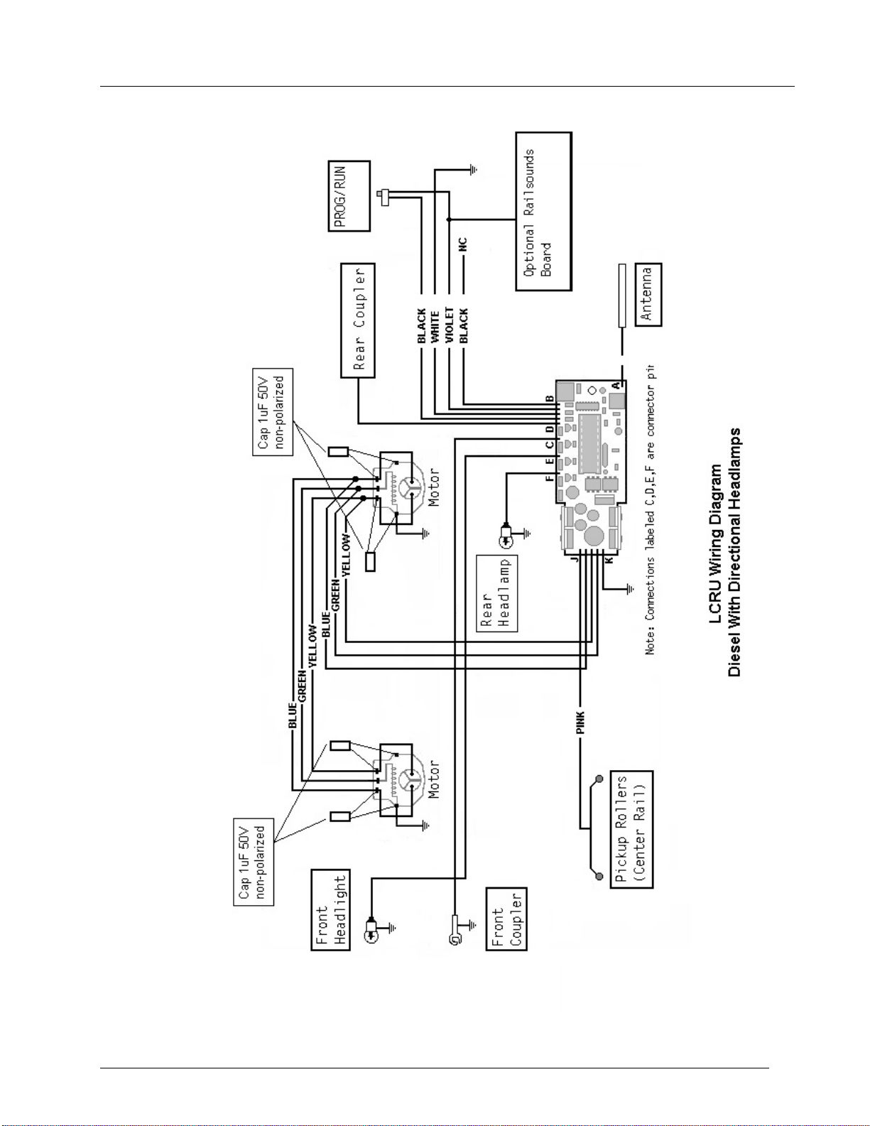
Fig. 5 Diesel With Directional Lighting.........................................................................................................................14
Fig. 6 Diesel With Strobe/MARs Light .........................................................................................................................15
Fig. 7 Steam With Smoke Unit......................................................................................................................................16
Limited WarrantyLimited Warranty 1717
RepairsRepairs 1717

LCRU Installation Manual
Digital Dynamics
2
IntroductionIntroduction
Please take the time to read and thoroughly understand the instructions in this manual. While
it is unlikely that any damage may occur to your engine, improper installation of the Lionel
LCRU may cause permanent damage to its circuit components.
A minimum amount of soldering skill is required to perform this installation correctly. If you
feel that you do not possess the proper soldering equipment or the expertise, you should refer
installation to your dealer or to Digital Dynamics.
If you think that the wiring of your particular engine is different from what is described in
this manual, do not attempt installation unless you have some experience with AC motor circuits.
Instead, contact Digital Dynamics for assistance.
Installation InstructionsInstallation Instructions
The Lionel LCRU can be installed into almost any Postwar or modern era Lionel locomotive with
little or no difficulty. While these instructions describe specific installation examples, they
should serve as guidelines for installation into any locomotive provided there is sufficient
mechanical clearance to do so. The wiring examples shown here are very similar, if not
identical, to those of other Lionel locomotives not specifically mentioned in this
documentation.
* * * Important Note! * * *
The Lionel LCRU is designed exclusively for AC motor locomotives. It cannot be used with DC
motor locomotives such as those produced by MTH, K-Line, Weaver, or Williams. If you are unsure
which type of motor you have, contact Digital Dynamics for assistance.
Tools Required
§Low power soldering iron
§Rosin core solder
§Small wire cutters
§Small long-nosed pliers
§Wire strippers
§Small flat blade screwdriver
§Small Phillips screwdriver
§Razor Blade or Exacto Knife
What’s Supplied
§LCRU circuit board
§Plug-in Antenna
§Four (4) plug-in hookup wires
§Four (4) 1uF non-polarized capacitors
§Four (4) solder washers
§Plastic Ty-Wraps
§Wire Nuts
§Three (3) Double Sided Foam Adhesive Tape Strips
§One #4 x 1/4" sheet metal screw

LCRU Installation Manual
Digital Dynamics
3
Preparation and Circuit Board InstallationPreparation and Circuit Board Installation
Installation with Railsounds 2.5Installation with Railsounds 2.5
If you are installing the LCRU in conjunction with a Railsounds 2.5 board, please review the
mounting instructions included with the Railsounds kit. After you have completed the mechanical
installation of the two boards, return to the next section of this manual for instructions on
how to complete the electrical connections.
Diesel or Other Plastic Body LocomotivesDiesel or Other Plastic Body Locomotives
Remove the body from the locomotive and place it aside where it cannot be damaged. Remove all
headlamp bulbs from the chassis so they are not broken during the installation. Place the
chassis on a clean, level work surface.
In the following steps, all wires are to be removed by unsoldering them from their connections.
Do not cut any wires unless you are instructed to do so.
1. Remove the three wires that connect the E-unit to the motor(s) by unsoldering them at the
motor. Usually, these wires are colored blue, green, and yellow. Make a note of the
connections before you remove them. In dual motor units, there will be an additional set of
blue, green, and yellow wires that connect from the first to the second motor. In some
instances, the wires may all be black. Avoid removing these wires.
2. Disconnect the E-unit connections to the pickup rollers. Depending upon the model of
locomotive, there may be one or two of these wires. In either case, they are usually
colored red and come directly from the truck mounted pickup roller and are soldered to a
common point on the E-unit.
3. Unsolder the wire that leads to the headlamp socket from the E-unit. This wire is usually
black and may be soldered to the same point as the pickup roller wires.
4. If you are installing the LCRU into a modern locomotive, skip the next steps and go on to
the next section.
5. Remove the red wire connecting the E-unit to the horn relay.
6. Loosen the single screw on the side of the E-unit and remove it from the chassis.
7. At the horn relay, unsolder the black wire connected to the horn.
8. Remove the two screws located at the base of the Relay Bracket.
9. Lift the Relay Bracket from the chassis. Be sure to save the insulator, screws, and
shoulder washers should you ever desire to restore the engine to its original configuration.
The variety of engine types produced by Lionel over the years eliminate the possibility of
describing a single mounting procedure that will apply to every case. Examine the layout of
your engine carefully and read the following section before deciding on the best mounting method
for the circuit board.
Method A
This method works best when there is a sufficiently large, flat area on the chassis to which the
board can be easily attached with adhesive foam tape. This method should work with most engines
having a stamped sheet metal chassis. It is also the preferred method for mounting the board
within the fuel tank of a die cast chassis such as the F3.
1. Remove the backing from two of the foam tape strips, and attach them side by side to the
bottom of the LCRU circuit board as shown in the picture below.
2. Using a razor blade or Exacto knife, trim approximately 1/4" from the remaining piece of
tape, and apply it to the back of the board. Do not discard the small left over piece of
tape. Do not touch the face of the tape once the backing has been removed.
3. Make sure that the intended circuit board mounting area is clean and oil-free. Clean the
surface with alcohol before attaching the circuit board.

LCRU Installation Manual
Digital Dynamics
4
4. Locate the circuit board over any free horizontal chassis surface. Orient the board so that
its wires are closest to the motor. Carefully press down on the circuit board to engage the
foam tape to the chassis.
5. Inspect the underside of the circuit board to be sure that there are no parts of the circuit
in contact with the metal chassis.
Figure 1
Method B
The LCRU has provisions for conventional mechanical fastening to an engine chassis. In some
cases, it may be possible to take advantage of existing chassis features to firmly mount the
LCRU. Generally, a Lionel stamped sheet metal chassis has an E-unit bracket that consists of a
tab bent up from the chassis. Engines such as the FM Trainmaster, EP-5, GP-7/9, and others have
this feature.
1. Place the LCRU board on its side, and align one of the three (3) holes on the bottom of the
heatsink with the slot in the E-unit bracket.
2. Place a strip of adhesive foam tape along the bottom edge of the LCRU board. The bottom
edge is opposite the side that has the four posts for making connections to the headlamps
and electrocouplers.
3. Referring to the photograph below, attach the heatsink to the bracket using the supplied #4
1/4" sheet metal screw. Be absolutely certain that the screw does not make contact with the
circuit board after it has been tightened against the E-unit bracket. Damage to circuit
boards shorted out in this manner will void the warranty.

LCRU Installation Manual
Digital Dynamics
5
Figure 2 - Heatsink Mounting Method in a Post War EP-5
Die-Cast Steam LocomotivesDie-Cast Steam Locomotives
In many, but not all cases, there is insufficient space within a steam locomotive to install the
LCRU, so installation within the tender is the only alternative. Depending upon the tender, you
may need to remove the air whistle assembly in order to free a large enough space. Note that
the LCRU IS NOT capable of operating a Post War air whistle without additional circuitry, so
it's removal should be of little consequence.
Electrical connections between the locomotive and tender are made via a special 8-pin connector
set available from Digital Dynamics.
Installing the PROG/RUN SwitchInstalling the PROG/RUN Switch
The PROG/RUN switch should be positioned in a convenient location where it can easily be changed
if required. Examine the switch before installing it. There are three solder posts on the
switch, but only two wires are soldered to it. When the switch slide is directly over the two
wired terminals, the switch is in the RUN position. Conversely, when the switch is over the
unused contact, it is in the PROG position.
1. Use the small remaining piece of foam tape to attach the switch to the chassis. Remove the
paper backing from the tape, and place the tape on the side of the switch.
2. Press the switch firmly against the chassis. If possible, locate the switch where it may be
accessed by opening a battery cover, and orient it so that the RUN position faces the front
of the locomotive.
3. If your engine has a proper sized switch cut-out in the chassis, you can mount the switch
there as well. You will need to provide the proper mounting hardware to do this.
Avoid unnecessary handling of the switch, as the wires that are soldered to it may break off if
they are flexed excessively
LCRU Installation Manual
Digital Dynamics
6
WiringWiring
LCRU and Engine TypeLCRU and Engine Type
The LCRU is programmed via two pigtail wires, BLK and WHT, for different options with different
locomotive types. Refer to the table below and to the wiring diagrams for these options and how
to enable them.
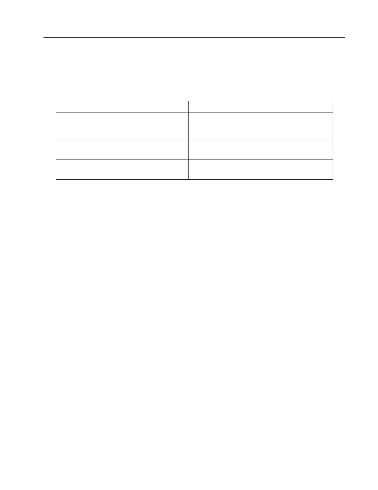
MODE WHT WIRE BLK WIRE REMARKS
STEAM w/ SMOKE GND GND Single Headlamp. Rear
Headlamp output drives
smoke unit.
DIESEL w/ DIRECTIONAL
HEADLAMPS GND No Connect Headlamps light in
direction of engine.
DIESEL w/ STROBE Connect to BLK Connect to WHT Rear Headlamp output
becomes strobe/MARS lamp.
Table 1. LCRU Programming
Note that later versions of the LCRU, specifically LCRU2 and R2LC, are programmed via CAB-1 for
operation with specific engine types and options. The LCRU will not respond to any of these
factory reset codes, and can be programmed only via the method described above.

LCRU Installation Manual
Digital Dynamics
7
Diesels and Similar Type EnginesDiesels and Similar Type Engines
Motors
With the LCRU board firmly in place, wiring of the motor(s) is a simple task. Read the
instructions carefully and proceed. Refer to the appropriate wiring diagram for clarification.
1. This step applies to engines with vertically oriented motors only. Remove one of the screws
that hold the motor assembly together. Slide one of the supplied solder washers over the
screw and replace it in the motor. Orient the arm of the terminal so that it is parallel to
the locomotive chassis. Before tightening the screw all the way, be sure that the solder
washer will not interfere with the locomotive body when it is installed.
2. If your engine is equipped with the old style horizontal motors, you cannot use the solder
washers since they are too large. Instead, loosen the motor screws, wrap the capacitor
leads around the screw, and re-tighten the screw.
3. Repeat this procedure for the other motor screw. Then, if you are connecting a dual motor
locomotive, repeat the entire procedure for the remaining motor.
4. Connect a non-polarized 1uF capacitor from one of the motor brush terminals to the adjacent
solder washer you just installed. Do not solder at this point, but wrap the capacitor leads
around the terminals once, using a small pair of long-nosed pliers. Repeat his procedure
for the other brush terminal, and the second motor, if so equipped.
5. Locate the three (3) LCRU motor leads. These are colored Blue, Green, and Yellow.
6. Dress the three leads to the motor. Avoid running the leads where they may interfere with
free movement of the truck assembly.
7. Solder the Green lead to the motor field terminal. This is usually the center terminal on
the motor. For dual motor locomotives, solder the field wire together with the field wire
from the other motor.
8. Solder the Yellow lead to the motor brush terminal along with the motor capacitor lead, and
the yellow lead from the second motor, if any.
9. Solder the remaining Blue motor lead to the remaining motor brush terminal along with the
other motor capacitor lead, and the remaining field lead from the second motor, if any.
10. Identify the Black AC return (GND) wire coming from the board. This wire is adjacent to the
Green motor wire.
11. Twist the Black return wire together with the appropriate LCRU programming wire. Refer to
Table 1 and to the diesel wiring diagrams in order to determine which connection should be
made for your board type and engine.
12. Connect these two wires to a solid chassis ground. It is extremely important that a good
electrical ground is obtained, or else erratic operation may result. If possible, solder
the ground leads directly to the motor, keeping the leads as short as possible. Be sure
that any paint or grease is removed from the area where the ground wire is attached.
13. Apply solder to all of the motor solder washer connections that remain.
Engines Equipped With Two Position E-Units
Some of the older, more common Lionel engines, particularly those designated as O-27 types, come
equipped with a two position E-unit instead of the more complex three position type. These
engines use a double-wound field coil in place of the complicated three position E-unit
mechanism to reverse motor direction. Wiring the LCRU to this type of motor is done as follows:
1. Solder the Yellow LCRU lead to one of the motor brush terminals.
2. Solder the Blue lead to the remaining motor brush terminal.
LCRU Installation Manual
Digital Dynamics
8
3. Identify the two field windings on the motor. One of the coils is wound in green colored
wire, while the other is an orange color. Select one of the coils, it makes no difference
which, and connect it to the GRN LCRU wire. The other coil is not connected and its end
should be wrapped with electrical tape.
Connecting Power Leads
Depending upon the locomotive, it will have either one or two power collectors, a dual roller
collector mounted on the front truck, or a single roller type mounted on both the front and rear
trucks. In either case, the connection procedure is the same, but must be repeated for
locomotives equipped with two single roller collectors.
1. Locate the wire(s) coming from the power pickup roller(s).
2. Using a pair of cutters, clip off a small amount of the exposed wire to remove all old
solder from the strands.
3. Strip the insulation back so that you have approximately 3/8” of clean, exposed wire.
Using one of the supplied wire nuts, twist together the wire(s) coming from the pickup roller(s)
together with the Pink power lead from the LCRU circuit board. Remember to keep the wires as
short as possible without their interfering with truck movement.
Diecast Steam EnginesDiecast Steam Engines
Electrical connections from the tender mounted LCRU to the engine are made through an eight-pin
connector assembly available from Digital Dynamics.
1. Remove the shell from the tender and place it aside where it cannot be damaged. Place the
chassis on a clean, level work surface.
2. Disconnect the wires from the whistle relay to the whistle motor.
3. Remove the wires connecting the whistle motor to the pickup rollers.
4. Remove the whistle motor by unfastening the nuts from underneath the chassis.
5. Remove the two screws located at the base of the Relay Bracket.
6. Clean any grease, oil, or loose rust from the chassis surface.
7. Attach the LCRU to the tender chassis using the supplied foam adhesive tape. Apply the tape
to the LCRU in the same pattern shown in the previous section.
8. Feed the wires from the 8-pin MALE connector through an opening in the engine side of the
tender. The MALE connector is the one with the seven equal length wires attached. Most
Lionel tenders have an opening to allow air to enter the air whistle.
9. Make all LCRU connections for headlamp, smoke unit, motor, power and chassis ground to the
wires of the connector assembly. Use the wire nuts enclosed with the kit to make the
connections.
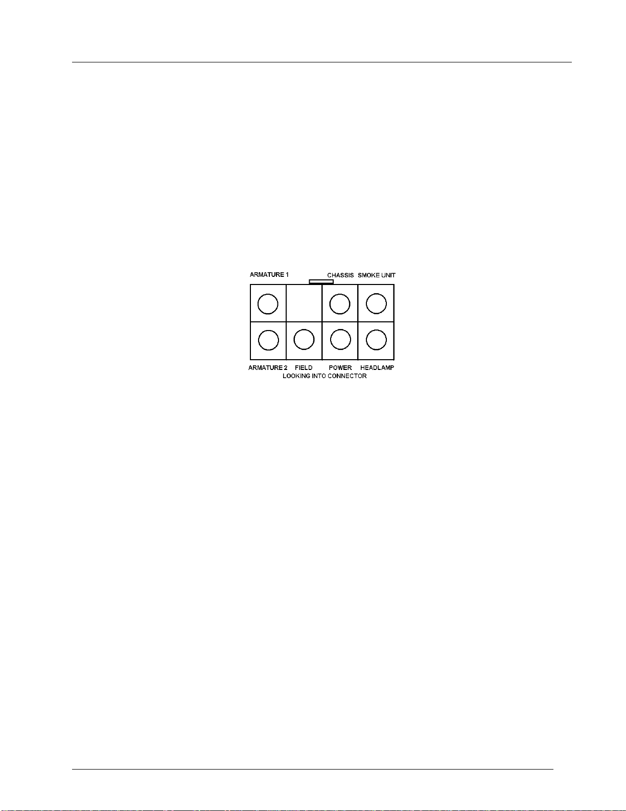
10. Connect the Black programming wire located adjacent to the wires leading to the PROG/RUN
switch, to chassis ground. Refer to the diagram below, and the Steam Wiring Diagram located
in the back of this manual for reference.
Figure 3. Steam Connector - Tender Side
LCRU Installation Manual
Digital Dynamics
9
11. If the tender is equipped with an electrocoupler, connect it to the LCRU using one of the
supplied connector wires and a wire nut.
12. After completion of the tender wiring, remove the engine boiler from the chassis.
13. Remove the wiring from the E-unit to the motors by unsoldering the connections at the motor.
14. Unsolder the E-unit connections to the headlamp, smoke unit, and pickup rollers.
15. Remove the E-unit.
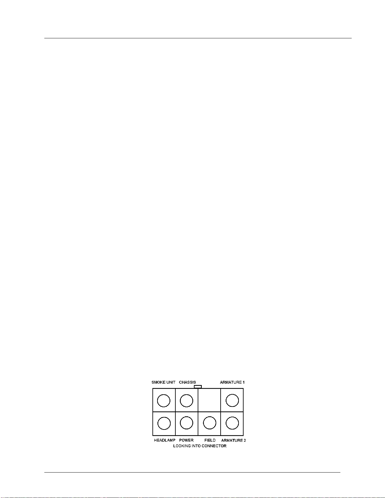
16. Layout the 8-pin connector assembly over the engine chassis, noting the wires and their
respective destinations. Note that the motor connections have the shortest wires, and the
connections to the headlamp and smoke unit have the longest wires. Make sure there is
enough slack in the cable to make connection to the tender.
17. Solder all connections to the motor, headlamp, smoke unit, pickup rollers and chassis. You
may need to make the chassis connection at the motor if there is no other available solder
point. Refer to the connector diagram below, and the Steam Wiring Diagram located in the
back of the manual.
Figure 4. Steam Connector - Engine Side
Smoke Unit Considerations
You may need to replace your older Postwar smoke unit with a newer liquid smoke type if you wish
to connect it to the LCRU. The LCRU is capable of supplying only 400mA, and if the resistance
of the smoke unit is too low, it will burn out the smoke unit driver.
Postwar type smoke units designed for use with smoke pellets consist of a few turns of nichrome
wire on a ceramic element. Usually, the resistance of these elements is very low. Measure the
resistance with an ohmmeter. If it is less than 30 ohms, you should replace it with a modern
type designed for use with liquid smoke before connecting it to the LCRU.
HeadlightsHeadlights
Lionel engines are equipped with a variety of headlamp types. The most popular styles found in
Postwar locomotives are the bayonet mount and the screw type. Modern-era engines are equipped
with several different styles, including lamp sockets having two wires instead of one. For this
type, the extra lead should be grounded to the chassis.
1. Locate the front headlamp wire. Using a pair of wire cutters, make a fresh cut on the end
of the wire to remove any solder, and strip away approximately 3/8" insulation.
2. Using a wire nut, connect the end of the headlamp wire to one of the supplied push-on
terminal connecting wires. You may want to shorten the wires before making a permanent
connection. Repeat this procedure for the backup lamp or strobe lamp if one is present on
the engine.
3. Locate the terminal posts on the side of the LCRU board. These are identified by the
letters D, C, E, F.
4. Re-install the bulb, making sure that it tightly engages the contact.

LCRU Installation Manual
Digital Dynamics
10
* * * Very Important * * *
The Trainmastersystem uses a constant 18V track voltage, The LCRU will supply the bulbs
in your engine with half the track voltage, or 9V in full command mode. However, the
lighting circuits of rolling stock will receive a full 18V, since their bulbs are usually
connected directly to track power. You will need to replace these bulbs before operating
them in the TrainmasterCommand Control environment. Alternatively, you can add a series
diode to your lighting circuits to lower the average voltage. Use a type 1N4001 diode
available at Radio Shack (p/n 276-1101).
Electromagnetic Coil CouplersElectromagnetic Coil Couplers
If your locomotive is equipped with electromagnetic coil couplers, you will want to connect them
to the LCRU for remote control operation. It is very easy to determine whether or not your
locomotive is equipped with this type of coupler. Look for a slide shoe on the underside of the
locomotive truck assembly. On most Postwar locomotives, this shoe is found in the center of the
front truck, in between the power pickup rollers. Note that the LCRU is not capable of
operating magnetic style couplers found on later Postwar equipment.
Electro-coupler kits are available from Digital Dynamics, Lionel and several parts dealers.
1. Disassemble the front truck pilot and coupler arm assembly.
2. Disconnect the wire leading from the pickup shoe to the front coupler. Unsolder it at both
ends.
3. Thread one of the unused hook-up wires through the chassis and truck assembly in the same
manner as the wire you just removed. Again, refer to the LCRU wiring diagram to determine
the correct connection.
4. Be absolutely certain that the wire is long enough to accommodate movement of the truck and
coupler before trimming it to length.
5. Repeat this procedure for the rear coupler using the appropriate wire.
Installing the AntennaInstalling the Antenna
Antenna installation and location is critical to making sure your engine functions reliably
under the TrainMaster system. The antenna must be located where it can best pick up the signal
radiating from the track. As a general rule, antenna location is fairly forgiving in plastic
bodied engines, as the plastic does not interfere with the radio signal. However, die-cast
locomotives will limit or completely block the signal from the antenna.
Plastic Body LocomotivesPlastic Body Locomotives
1. Remove the antenna from the parts kit. The antenna is the adhesive backed copper strip with
a wire soldered to it.
2. Place the locomotive body upside down on a soft surface such as an old towel, or a piece of
carpet.
3. Remove the adhesive backing from the copper strip.
4. Starting at the rear of the loco body, place the copper strip antenna lengthwise along the
inside center of the roof.
5. Extend the antenna wire for as long a distance as possible inside the locomotive, then loop
it back to where it will connect to the LCRU circuit board.
6. Under no circumstances should the antenna be attached to a metal chassis. Doing this will
short-circuit signal reception.
7. Place the locomotive body along side the chassis and plug the antenna into the Antenna
input, labeled 'A' at the corner of the LCRU circuit board. Refer to the wiring diagram for
the location of this connection.

LCRU Installation Manual
Digital Dynamics
11
8. Place the body on top of the chassis. Do not insert the screws until after tests are
completed.
Die-Cast LocomotivesDie-Cast Locomotives
Metal engine and/or tender bodies present a special problem for the TrainMastersystem, since
the radio signal cannot reach the circuit if the circuit and antenna are enclosed within.
If your tender has a plastic body, you may attach the antenna to the inside of the plastic shell
anywhere it is convenient. The orientation of the antenna should be parallel with the track
direction.
If you have a diecast tender shell, you will need to electrically isolate it from the chassis.
1. Using black electrical tape, cover the chassis at every location that comes in contact with
the tender shell. Usually, you need only wrap a continuous piece of tape around the sides
of the chassis with part of the tape overlapping on top. When the tender shell is
installed, the tape should not be visible.
2. Place the shell on the chassis, and use an ohmmeter to test for continuity. If you do not
have access to an ohmmeter, carefully inspect the chassis and tender shell for any areas
that may be in contact with each other. Correct as necessary.
3. Attach the antenna to the inside of the diecast shell. Place it over an area where there is
no paint. You may need to scrape away paint to make good electrical contact between the
antenna and the tender shell. Alternatively, you can remove the copper strip from the
antenna wire, and attach the exposed wire to any available hardware such as a nut, bolt, or
screw within the tender shell.
4. Fasten the tender shell to the chassis using nylon screws. These are available at most
hardware stores. After tightening the screws, make sure that there is still no electrical
continuity between the shell and chassis.
Testing Your InstallationTesting Your Installation
Before applying power to the locomotive, carefully inspect all solder connections for short
circuits and loose connections. Make sure all wire nuts are tight. Pay particular attention to
the underside of the circuit board, ensuring that it is not in contact with any metal parts of
the engine chassis. Also, it is important that any unused wires do not come in contact with any
part of the circuit or any exposed metal parts. Either cut-off unused wires, or wrap their ends
with electrical tape in order to prevent short circuits.
1. Remove all other locomotives from the track, and make sure that all power is OFF.
2. Make sure your Trainmastersystem is properly connected. Refer to the instructions that
came with your Lionel Trainmastersystem if you are not sure about the connections.
3. Verify that your system is operational by observing the indicators on the Command Base as
buttons are pressed on the CAB-1.
4. Place the locomotive on the track.
5. Hold the locomotive firmly while you apply power to the track. This will prevent possible
damage to your locomotive in the event of a malfunction due to improper installation.
6. Turn on power. Observe that the engine headlamp is lit and not flickering.
7. Make sure that none of the circuit components, including the wiring, are hot to the touch,
and that no smoke or burning odor is present. Otherwise, shut down power immediately.
8. Using the CAB-1 controller, press [ENG][1], then slowly turn the red button clockwise. If
the installation was performed properly, the engine will begin to move forward.
9. Use the Troubleshooting section to help you determine the problem if the engine does not
respond as it should.

LCRU Installation Manual
Digital Dynamics
12
Programming the Engine IDProgramming the Engine ID
The LCRU comes with its engine ID set to number ‘1’. If you want to change the engine ID,
follow this procedure.
1. Make sure the Command Base or PowerMaster is connected to the track. The PowerMaster
CMD/CONV switch must be set to the CMD position.
2. Set the engine PROG/RUN switch to PROG.
3. Place the engine on the track and apply power.
4. On the CAB-1, press [ENG] then the number (1 - 99) for the locomotive.
5. Press [SET]. The engine ID is saved forever, or until you decide to change it.
6. Remove power from the track and place the switch back into the ‘RUN’ position.
Sound SystemsSound Systems
The Lionel LCRU is designed to work exclusively with Lionel Railsoundsand SignalSounds.
There is no facility to connect any other type of sound system. Various Railsounds boards are
available from Digital Dynamics and come with complete instructions to connect to the LCRU.
Please call or write for further information. SignalSoundsboards for both steam and diesel
are also available on a limited basis.
Conventional Mode OperationConventional Mode Operation
In the absence of the command environment, an LCRU equipped engine will operate like one
equipped with a conventional E-unit, cycling from Neutral to Forward to Neutral to Reverse each
time power is momentarily interrupted. Cycling of locomotive direction can be overridden by
placing the Engine ID programming switch in the ’PROG’ position. This will lock the engine
direction into Forward. You must replace the switch back to the ‘RUN’ position if you wish to
run the engine in Command mode.
To test the engine in Conventional Mode:
1. Remove power from the Command Base by unplugging the wall transformer. Or, if you have a
Powermaster based system, set the PowerMaster switch to the CONV position.
2. Place the engine on the track.
3. Slowly increase the track voltage. The engine should begin to move in response to the
transformer setting.
4. Cycle the engine through FWD-NEUTRAL-REVERSE using the direction button, or by briefly
cycling power to the track. The engine should operate just like on equipped with a
mechanical E-unit, except that the lighting will be directional.
5. If the engine fails to respond in Conventional Mode, make sure the TrainMaster signal is not
present on an adjacent track, or anywhere else nearby. The only way to ensure this is to
completely remove power to the Command Base.
TroubleshootingTroubleshooting
When correctly installed, your TrainMasterLCRU will give years of reliable service. However,
improper installation may give less than optimum performance. First check all wires for solid,
reliable connections, then be absolutely certain that there are no short circuits, or bare wires
coming in contact with each other or the locomotive chassis. After this is done, use the
accompanying wiring chart to diagnose and any correct installation problems. If your specific
problem is not listed, or the suggested solution does not work for you, contact Digital Dynamics
for assistance.

LCRU Installation Manual
Digital Dynamics
13
Locomotive Starts Up in Conventional Mode Or Does
Not Respond to CAB-1 Commands
Check that the Trainmaster
System is operating properly using a
known working engine. Verify that the proper Engine ID is being
used at the CAB-1 Controller. Remember that the default engine ID
# is set to ‘1’. See the instructions under the heading “Poor
Signal Reception’.
Reset the Engine ID.
Locomotive Direction Is Out Of Sync With Headlamps
Either the headlamp wiring is reversed, or the motor armature
wires (BLU or YEL) are reversed. If the default start-up
direction in command mode is reverse, then the motor(s) are
incorrectly wired. Reverse the BLU and YEL motor leads.
Otherwise, simply reverse the front and rear headlamp wiring
(applies to dual headlamp locos only).
Locomotive Runs In One Direction Only
One of the motor armature wires has been reversed with the field
wire. Another possibility is that your Lionel locomotive was
equipped with a 2-position E-unit, which is wired differently than
the traditional scheme. Contact Digital Dynamics for
instructions.
Locomotive stops for no apparent reason
There are two possible causes for this, poor signal reception or
excessive electrical noise. See following.
Poor Signal Reception
The LCRU microprocessor is programmed in such a way that if it
loses contact with the Trainmaster
radio signal, even for a
fraction of a second, it will immediately halt the engine. This
safety precaution was included to prevent your train from
suffering damage should it run out of control. Make sure that your
Command Base is connected to the track properly and is receiving
AC power from its wall transformer.
Verify that the Command Base is receiving commands from your CAB-1
remote. The indicators on the CAB-1 will change from RED to GREEN
as it receives a signal from the CAB-1 indicating that buttons are
pressed.
Ensure that the locomotive antenna is properly connected to the
circuit board, and that the antenna wire is oriented correctly
inside the locomotive body. For optimum reception of the radio
control signal, the antenna should be directed parallel to the
rails.
Excessive Electrical Noise
If the problem seems to be speed related, i.e. the locomotive
seems to stop frequently when run at moderate to high speeds, but
operates correctly at low speeds, then the problem is most likely
due to excessive motor noise and/or arcing of the pickup rollers.
Older dual-motor locomotives, particularly those with horizontal
style motors, are more prone to generating excessive electrical
noise than are single motor locomotives. There are some measures
that can be taken to reduce noise, including replacement of the
motor brushes with the newer style bonded wire brushes, available
from Lionel, from Lionel Service Centers, or from any of the many
suppliers of train repair parts.
Other measures you can take to reduce electrical noise include
thoroughly cleaning your track and engine pickup rollers, cleaning
and resurfacing the motor brushes and armature, and replacing the
pickup rollers if they show signs of excessive wear. If
necessary, bend the pickup roller arm so that it exerts maximum
pressure on the track
Electrocouplers Open Randomly or Headlamps Flicker
Trim excessive lead lengths wherever possible and dress the wires
controlling lamps and couplers as far away as possible from motor
and power pickup leads, and form a twisted wire pair with the
power lead and ground lead wherever possible. Insert a 1/4W
resistor in series with the LCRU board and the headlamp and/or
electrocoupler. Use a value of 5.6 Ohms to 10 Ohms, whichever
works best.
LCRU Installation Manual
Digital Dynamics
14
Fig. 5 Diesel With Directional Lighting

LCRU Installation Manual
Digital Dynamics
15
Fig. 6 Diesel With Strobe/MARs Light

LCRU Installation Manual
Digital Dynamics
16
Fig. 7 Steam With Smoke Unit

LCRU Installation Manual
Digital Dynamics
17
Limited WarrantyLimited Warranty
Digital Dynamics warrants to the original consumer purchaser that this product will be free of
defects in materials and workmanship for a period of one year from the date of original
purchase. This warranty does not cover service, repair, or replacement to correct any damage
caused by improper installation, improper connection, external electrical fault, accident,
disaster, misuse, abuse, or modifications to the product. All other express or implied
warranties, including the implied warranty of merchantability and fitness for a particular
purpose, are hereby disclaimed.
If this product is not in good working order as warranted, the sole and exclusive remedy shall
be repair or replacement. In no event shall Digital Dynamics, or any dealer, distributor, or
authorized installation and/or repair service provider be liable for any damages in excess of
the purchase price of the product. This limitation applies to damages of any kind, including
but not limited to, direct or indirect damages, lost profits, lost savings or other special,
incidental, exemplary or consequential damages whether for breach of contract, tort or
otherwise, or whether arising out of the use of or inability to use the product, even if Digital
Dynamics, or any dealer, distributor, or service provider has been advised of the possibility of
such damages or any claim by any other party. Some states do not allow the exclusion or
limitation of incidental or consequential damages so the above limitation or exclusion may not
apply to you.
During this one year warranty period, the product will either be repaired or replaced (at our
option) without charge to the purchaser, when returned either to the dealer with proof of the
date of purchase or directly to Digital Dynamics when returned prepaid and insured with proof of
date of purchase.
Some states do not allow limitations on how long an implied warranty lasts, so such limitations
may not apply to you. This warranty gives you specific legal rights, and you may also have
other rights which vary from state to state.
RepairsRepairs
Each and every LCRU has been thoroughly tested before it is shipped. The likelihood that it is
not working when it reaches you is very small. However, if after troubleshooting it yourself
you cannot get it to work properly, you should return it along with your engine to Digital
Dynamics postage paid. Do not remove the board from the engine, and include a note indicating
the problem. Enclose a check for $20 to cover troubleshooting and return shipping. If you want
the parcel insured beyond $100, enclose an additional $5.
Should your LCRU ever need repair, you should return it postpaid directly to Digital Dynamics.
If your LCRU is in warranty, it will be repaired and returned to you free of charge. Units out
of Warranty will be repaired for a service charge of $20. Do not send the entire locomotive
unless you are instructed to do so. Please call or email for return authorization before
returning anything.
To obtain return authorization call (203) 778-3599, 11 AM to 7 PM (EST), or by email to
Trainmaster, and Railsounds, are trademarks of Lionel, LLC
MTHis a trademark of MTH Electric Trains, Inc.
Table of contents


