Digital Electronics GP-2401 Series User manual

GP-2401/2501/2601 Series
User Manual
Digital Electronics Corporation

1
Thank you for purchasing the Pro-face GP-2401/2501/2601 Series programmable
operator interface (hereafter referred to as the "GP unit").
This GP unit, with its expanded functionality and improved overall performance,
is an upgrade of Pro-face's previous GP series panels. GP-2401/2501/2601 Series
units allow you to use the CF Card without attaching separately sold expansion
units.
Please read this manual carefully as it explains, step by step, how to use the GP
correctly and safely.
Also, in this manual's examples, the Mitsubishi MELSEC-AnA Series PLC is
referred, whenever possible, as a point-to-point connection.
<Note>
1) It is forbidden to copy the contents of this manual, in whole or in part, except
for the user’s personal use, without the express permission of Digital Electron-
ics Corporation of Japan.
2) The information provided in this manual is subject to change without notice.
3) This manual has been written with care and attention to detail; however, should
you find any errors or omissions, please contact Digital Electronics Corporation
and inform them of your findings.
4) Please be aware that Digital Electronics Corporation shall not be held liable by
the user for any damages, losses, or third party claims arising from any uses of
this product.
All Company/Manufacturer names used in this manual are the registered trade-
marks of those companies.
© 2003 Digital Electronics Corporation
Preface

Preface
GP-2401/2501/2601 Series User Manual
2
Table of Contents
Preface........................................................................................................................ 1
Essential Safety Precautions ................................................................................... 6
General Safety Precautions ................................................................................... 10
GP-2401/2501/2601 Series Models....................................................................... 12
Package Contents ................................................................................................... 12
UL/c-UL (CSA) Application Notes ...................................................................... 13
CE Marking Notes................................................................................................ 14
Revision Version ..................................................................................................... 15
Documentation Conventions .................................................................................. 16
CHAPTER 1 INTRODUCTION
1.1 Prior to Operating the GP............................................................................1-1
1.2 System Design...............................................................................................1-2
1.2.1 GP-2401/2501/2601 Series System Design .......................................1-2
1.3 Accessories....................................................................................................1-5
CHAPTER 2 SPECIFICATIONS
2.1 General Specifications .................................................................................2-1
2.1.1 Electrical..............................................................................................2-1
2.1.2 Environmental ......................................................................................2-2
2.1.3 Structural .............................................................................................2-3
2.2 FunctionalSpecifications .............................................................................2-4
2.2.1 Display.................................................................................................2-4
2.2.2 Memory...............................................................................................2-5
2.2.3 Touch Panel • Clock............................................................................2-5
2.2.4 Interfaces............................................................................................2-6
2.3 Interface Specifications................................................................................2-7
2.3.1 SerialInterfaces...................................................................................2-7
2.3.2 PrinterInterface...................................................................................2-8
2.3.3 AUXInput/Output I/F.........................................................................2-9
2.4 Part Names and Functions ......................................................................... 2-11

GP-2401/2501/2601 Series User Manual 3
Preface
2.5 Dimensions ..................................................................................................2-13
2.5.1 GP-2401Series External Dimensions ...............................................2-13
2.5.2 GP-2501Series External Dimensions ...............................................2-14
2.5.3 GP-2601Series External Dimensions ...............................................2-15
2.5.4 PanelCutDimensions........................................................................2-16
2.5.5 InstallationFasteners .........................................................................2-16
CHAPTER 3 INSTALLATION AND WIRING
3.1 Installation.....................................................................................................3-1
3.1.1 InstallationProcedures ........................................................................3-1
3.2 WiringPrecautions........................................................................................3-6
3.2.1 Connecting the Power Cord................................................................3-6
3.2.2 Connecting the Power Supply ............................................................3-8
3.2.3 Grounding............................................................................................3-9
3.2.4 I/OSignalLinePlacement ...................................................................3-9
3.3 Tool Connector ............................................................................................3-10
3.4 CF Card Installation and Removal ........................................................... 3-11
3.4.1 CF card Handling ..............................................................................3-13
3.5 Attaching the Screw Lock Terminal Block ..............................................3-14
CHAPTER 4 DATA TRANSFER
4.1 Serial Data Transfer.....................................................................................4-1
4.2 Ethernet Data Transfer................................................................................4-4
4.3 CF Memory Loader Tool .............................................................................4-5
4.3.1 Data Upload and Download................................................................4-6
CHAPTER 5 OFFLINE MODE
5.1 Entering OFFLINE Mode...........................................................................5-1
5.1.1 After Plugging in the Power Cord........................................................5-1
5.1.2 From the Menu Bar .............................................................................5-2
5.2 OFFLINE Mode Main Menu......................................................................5-3
5.3 INITIALIZATION ........................................................................................5-4
5.4 SELF-DIAGNOSIS.......................................................................................5-6
CHAPTER 6 INITIALIZING THE GP
6.1 Initialization Screen ......................................................................................6-1
6.2 InitializationItems ........................................................................................6-2

Preface
GP-2401/2501/2601 Series User Manual
4
6.3 SYSTEM ENVIRONMENT SETUP..........................................................6-3
6.3.1 SYSTEM SETUP ...............................................................................6-3
6.3.2 SYSTEM AREA SETUP....................................................................6-4
6.3.3 GLOBAL WINDOW SETUP ............................................................6-6
6.3.4 CHARACTER STRING DATA SETUP.............................................6-7
6.4 SET UP I/O ..................................................................................................6-10
6.4.1 SET UP SIO .....................................................................................6-10
6.4.2 SET UP PRINTER............................................................................6-12
6.4.3 SET UP TOUCH PANEL.................................................................6-15
6.4.4 COMMUNICATION SETUP..........................................................6-18
6.4.5 SoundSettings...................................................................................6-19
6.4.6 EXPANSION SERIAL COMMUNICATION SETUP ...................6-20
6.4.7 EXPANSION SERIAL ENVIRONMENT SETUP.........................6-21
6.4.8 SETUP CAPTURE OPERATION....................................................6-21
6.4.9 DISPLAY DEVICE SETTINGS ......................................................6-22
6.4.10 FUNCTION SETUP ........................................................................6-22
6.4.11 COMMUNICATION PORT SETUP...............................................6-23
6.5 PLC SETUP ................................................................................................6-24
6.5.1 SET UP OPERATION SURROUNDINGS(1:1/n:1) .......................6-24
6.5.2 STATIONSETUP(n:1) .....................................................................6-25
6.5.3 CUSTOMIZE SETUP (n:1)..............................................................6-27
6.6 INITIALIZE INTERNAL MEMORY ...................................................6-29
6.6.1 INITIALIZE GP MEMORY.............................................................6-29
6.6.2 INITIALIZE CF CARD....................................................................6-29
6.6.3 CSV DATA INDEX..........................................................................6-30
6.7 SET UP TIME .............................................................................................6-31
6.8 SET UP SCREEN .......................................................................................6-32
CHAPTER 7 RUN MODE AND ERRORS
7.1 RUN Mode...................................................................................................7-1
7.1.1 After Connecting the Power Cord.......................................................7-1
7.1.2 Via OFFLINE Mode...........................................................................7-2
7.2 SELF-DIAGNOSIS....................................................................................... 7-3
7.2.1 SELF-DIAGNOSIS ITEM LIST........................................................7-3
7.2.2 SELF-DIAGNOSIS - Details..........................................................7-4

GP-2401/2501/2601 Series User Manual 5
Preface
7.3 Troubleshooting.............................................................................................7-8
7.3.1 Possible Types of Trouble ...................................................................7-8
7.3.2 NoDisplay ..........................................................................................7-9
7.3.3 NoGP/HostCommunication.............................................................7-12
7.3.4 Touch Panel Does Not Respond .......................................................7-14
7.3.5 Buzzer Sounds when GP power is turned ON ..................................7-15
7.3.6 Clock Settings Cannot be Entered ....................................................7-16
7.3.7 Error Screens ....................................................................................7-16
7.4 Error Messages ..........................................................................................7-17
7.4.1 Error Message List ............................................................................7-17
7.5 Error Message Details .............................................................................7-19
7.5.1 SYSTEM ERRORS ..........................................................................7-19
7.5.2 ILLEGAL ADDRESS IN SCREEN DATA......................................7-21
7.5.3 PLC COM. ERROR .........................................................................7-22
7.5.4 CLOCK SET UP ERROR................................................................7-23
7.5.5 SCREEN TAG LIMIT EXCEEDED (max. of 384)..........................7-23
7.5.6 OBJ. PLC HAS NOT BEEN SETUP ..............................................7-23
7.5.7 D-Script and Global D-Script Errors ................................................7-24
7.5.8 Extended SIO Script Error................................................................7-25
7.5.9 Serial I/F Change Error .....................................................................7-25
CHAPTER 8 MAINTENANCE
8.1 Regular Cleaning ..........................................................................................8-1
8.1.1 CleaningtheDisplay ............................................................................8-1
8.1.2 InstallationGasketCheck/Replacement ..............................................8-1
8.2 Periodic Check Points...................................................................................8-3
8.3 Replacing the Backlight...............................................................................8-4
8.3.1 Replacing CA3-BLU12-01.................................................................8-6
INDEX

Preface
GP-2401/2501/2601 Series User Manual
6
This manual includes procedures that must be followed to operate the GP cor-
rectly and safely. Be sure to read this manual and any related materials thoroughly
to understand the correct operation and functions of this unit.
Safety Icons
Throughout this manual the following icons are provided next to GP operation
procedures requiring special attention, and provide essential safety information.
These icons indicate the following levels of danger:
Indicates situations where severe bodily
injury, death or major equipment damage
can occur.
Indicates situations where slight bodily
injury or machine damage can occur.
System Design
• Do not create GP touch panel switches that could possibly
endanger the safety of equipment and personnel. Damage
to the GP, its I/O unit(s), cable(s), and other related equip-
ment can cause an output signal to remain continuously
ON or OFF and possibly cause a major accident. There-
fore, design all monitoring circuits using limit switches,
etc. to detect incorrect device movement. To prevent acci-
dents related to incorrect signal output or operation, de-
sign all switches used to control vital machine operations
so they are operated via a separate control system.
• Please design your system so that equipment will not
malfunction due to a communication fault between the GP
and its host controller. This is to prevent any possibility of
bodily injury or material damage.
• Do not use the GP unit as a warning device for critical
alarms that can cause serious operator injury, machine
damage or production stoppage. Critical alarm indicators
and their control/activator units must be designed using
stand-alone hardware and/or mechanical interlocks.
• The GP is not appropriate for use with aircraft control
devices, aerospace equipment, central trunk data trans-
mission (communication) devices, nuclear power control
devices, or medical life support equipment, due to these
devices’ inherent requirements of extremely high levels of
safety and reliability.
Essential Safety Precautions
Caution
Warning
WARNINGS

GP-2401/2501/2601 Series User Manual 7
Preface
WARNINGS
• Do not create switches used to control machine safety
operations, such as an emergency stop switch, or a GP
touch screen icon. Be sure to install these switches as
separate hardware switches, otherwise severe bodily
injury or equipment damage can occur.
• When using the GP with : transportation vehicles (trains,
cars and ships), disaster and crime prevention devices,
various types of safety equipment, non-life support re-
lated medical devices, etc., redundant and/or failsafe sys-
tem designs should be used to ensure the proper degree
of reliability and safety.
Touch Panel
• After the GP’s backlight burns out, unlike the GP’s
“Standby Mode”, the touch panel is still active. If the op-
erator fails to notice that the backlight is burned out and
touches the panel, a potentially dangerous machine op-
eration error can occur.
If your GP's backlight suddenly turns OFF, use the follow-
ing steps to determine if the backlight is actually burned out.
1) If your GP is not set to "Standby Mode" and the
screen has gone blank, your backlight is burned out.
2) Or, if your GP is set to Standby Mode, but touching
the screen does not cause the display to reappear,
your backlight is burned out.
Also, use the GP’s built-in “USE TOUCH PANEL AFTER
BACKLIGHT BURNOUT” feature to prevent an accidental
machine operation error. This feature can automatically
detect a burnout and disable the touch screen.
Wiring
• To prevent an electric shock, be sure to confirm that the
GP's power cord is not connected to the main power
when connecting power lines to the GP.
• Be sure to replace the GP's plastic terminal block cover
after wiring is completed, since operating the GP without
the cover may lead to an electric shock
• Do not use power beyond the GP's specified voltage
range. Doing so may cause a fire or an electric shock.

Preface
GP-2401/2501/2601 Series User Manual
8
Installation/Maintenance
• Be sure to securely connect all cable connectors to the GP.
A loose connection may cause incorrect input or output.
Battery Replacement
• The GP uses a lithium battery for backing up its internal
clock data. If the battery is incorrectly replaced, the bat-
tery may explode. To prevent this, please do not replace
the battery yourself. When the battery needs to be re-
placed, please contact your local GP distributor.
Installation/Maintenance
• High voltage runs through the GP. Except for replacing
the backlight, never take apart the GP, otherwise an elec-
trical shock can occur.
• Do not modify the GP unit. Doing so may cause a fire or
an electric shock.
• Do not use the GP in an environment where flammable
gasses are present, since operating the GP may cause an
explosion.
CAUTIONS
WARNINGS

GP-2401/2501/2601 Series User Manual 9
Preface
Wiring
• Ground the GP's FG line separately from other units’ FG
lines. Putting these FG lines too close may cause an elec-
tric shock or unit malfunction. Be sure to use a grounding
resistance of 100ΩΩ
ΩΩ
Ωor less and a 2mm2or thicker wire, or
your country’s applicable standard.
• Be sure the GP's rated voltage is within the designated
range, and that the power terminal lines are correctly
attached. If the voltage supplied differs from the rated
voltage, or incorrect wiring or grounding is performed, it
may cause a fire or unit malfunction.
• Use only the designated torque to tighten the GP's termi-
nal block screws. If these screws are not tightened firmly,
it may cause a short-circuit, fire, or GP malfunction.
• Be careful that metal filings and wiring debris do not fall
inside the GP, since they can cause a fire, GP malfunc-
tion, or incorrect unit operation.
Display Device/CF Card
• The liquid crystal panel contains a powerful irritant and if
for any reason the panel is damaged and this liquid con-
tacts any part of your body, be sure to wash that area with
running water for 15 minutes. If any of this liquid enters
your eye, flush your eye for 15 minutes with running water
and contact a physician.
• Prior to inserting or removing a CF Card, be sure the CF
Card ACCESS lamp is not lit. If you do not, CF Card inter-
nal data may be damaged or lost.
• While a CF Card is being accessed, NEVER turn OFF or
reset the GP, or insert or remove the CF Card. Prior to
performing these operations, create and use a special GP
application screen that will prevent access to the CF
Card.
Refer to GP-PRO/PB III for Windows Tag Reference Manual
(included in the screen editor software package)
Unit Disposal
• When this unit is disposed of, it should be done so ac-
cording to your country's regulations for similar types of
industrial waste.
CAUTIONS

Preface
GP-2401/2501/2601 Series User Manual
10
General Safety Precautions
• Do not strike the touch panel with a hard or pointed object, or press
on the touch panel with too much force, since it may damage the
touch panel or the display.
• Do not install the GP where the ambient temperature can exceed the
allowed range. Doing so may cause the GP to malfunction or shorten
its operation life.
• Do not restrict or limit the GP’s naturally occurring rear-face ventila-
tion, or store or use the GP in an environment that is too hot.
• Do not use this unit in areas where large, sudden temperature
changes can occur. These changes can cause condensation to form
inside the unit, possibly causing the unit to malfunction.
• Do not allow water, liquids, metal or charged particles to enter inside
the GP’s case, since they can cause either a GP malfunction or an
electrical shock. The allowable pollution degree is 2.
• Do not use or store the GP in direct sunlight, or in excessively dusty
or dirty environments.
• Do not store or use the unit where strong jolting or excessive vibra-
tion can occur.
• Do not store or use the GP where chemicals (such as organic sol-
vents, etc.) and acids can evaporate, or where chemicals and acids
are present in the air.
Corrosive chemicals: Acids, alkalines, liquids containing salt
Flammable chemicals: Organic Solvents
• Do not use paint thinner or organic solvents to clean the GP.
• Do not store or operate the LCD display in areas receiving direct
sunlight, since the sun's UV rays may cause the LCD display’s qual-
ity to deteriorate.
• Storing this unit in areas at a temperature lower than is recommended
in this manual’s specifications may cause the LCD display’s liquid
to congeal, which may damage the panel. Conversely, if the storage
area’s temperature becomes higher than the allowed level, the LCD’s
liquid will become isotropic, causing irreversible damage to the LCD.
Therefore, be sure to store the panel only in areas where tempera-
tures are within those specified in this manual.
• Do not connect or disconnect the communication cable between the
GP and the host while power is ON.
• Due to the possibility of unexpected accidents, be sure to back up
the GP’s screen data regularly.

GP-2401/2501/2601 Series User Manual 11
Preface
About the GP's Display Panel
• The GP's currently displayed data, its voltage*1 and brightness set-
ting each affect the intensity of Contouring. (i.e, when some parts of
the screen are brighter than others, creating a wavelike pattern)
• There are minute grid-points (dark and light) on the Display Panel's
surface. This is part of the GP's design and not a defect.
• Extended shadows, or "Crosstalk" may appear on the sides of screen
images. This is normal for an LCD display.
• Sometimes the display area may look as if the display colors have
changed. This is a common attribute of LCD's and is not a defect.
• Displaying a single image for long periods can cause an afterimage
to remain when the display is changed to another screen.
To prevent this effect:
Use the GP's "Stand-by Mode", which automatically turns the
screen OFF when there is no input for a specified period of
time.
5.3.1 System Setup
• Write “FFFFh” to the System Data Area’s “Screen Display Off”
address *2 to turn the screen display OFF when the following ac-
tions are not performed for the user's designated period of time.
• Change Screen
• Touch Screen
• Alarm Display
Do not display any single screen for a long period of time. Try
to periodically change the screen display.
*1 If the GP's voltage is at the very low end of its allowable range, it may effect the
intensity of contouring.
*2 The following addresses assume all System Data Area settings are entered. If they are
not all entered, the correct word address may be different from those given here.
With the Direct Access Method — use System Data Area word address +9
With the Memory Link Method — use System Data Area word address +12
GP-PRO/PBIII for Windows Device/PLC Connection Manual
Preface
GP-2401/2501/2601 Series User Manual
12
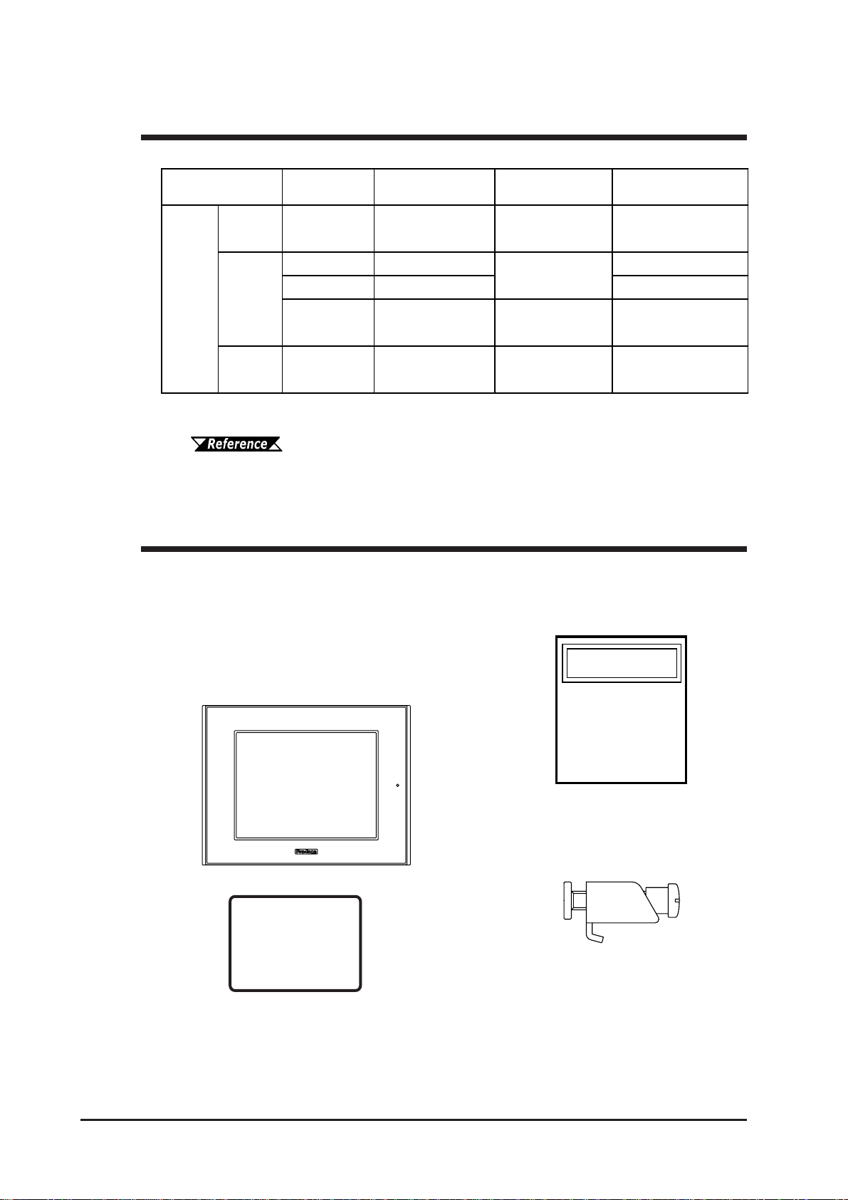
The GP's packing box contains the items listed below. Please check to confirm
that all items shown below have been included.
Package Contents
Installation Fasteners
(4/set)
Installation Guide (1)
This unit has been carefully packed, with special attention to quality. However,
should you find anything damaged or missing, please contact your local GP
distributor immediately for prompt service.
GP Unit (1)
GP2401-TC41-24V
GP2501-TC11
GP2501-SC11
GP2501-LG41-24V
GP2601-TC11
Installation
Guide
The GP-2401/2501/2601 Series refers to the following GP model numbers:
GP-2401/2501/2601 Series Models
*1 Revised models may or may not conform to UL/c-UL (CSA) and CE Markings,
depending on the revision version.
For information on how to determine the revision version, see "Revision
Version" (page 14).
Installation Gasket (1)
Model Name Model Type Comments GP Type in Screen
Creation Software
GP-2401
Series GP-2401T GP2401-TC41-24V UL/cUL Approved,
CEMarked GP2401
GP-2501T GP2501-TC11 GP2501
GP-2501S GP2501-SC11 GP2501S
GP-2501L GP2501-LG41-24V UL/cULApproved,
CEMarked GP2501L
GP-2601
Series GP-2601T GP2601-TC11 *1 GP2601
GP2000
Series
Series
*1
GP-2501
Series

GP-2401/2501/2601 Series User Manual 13
Preface
UL/c-UL (CSA) Application Notes
The GP2401-TC41-24V, GP2501-LG41-24V are UL/c-UL (CSA) listed products.
(UL file No.E182139)
The GP2501-TC11*1, GP2501-SC11*1, GP2601-TC11*1 are UL/c-UL (CSA) recog-
nized components. (UL file No.E231702)
These units conform to the following standards:
A) UL508 Industrial Control Equipment
B) UL60950 Safety Standard for Information Technology Equipment (3rd Edition,
issued December 1, 2001)
C) UL1604 Electrical Equipment for use in Class 1 & 2 - Division 2, or Class 3
Hazardous Locations.
D) CAN/CSA-C22.2, Nos. 142, and 213-M1987 Safety Standard for Information
Technology and Electrical Business Equipment
E) CAN/CSA-C22.2 No. 1010-1
Safety Requirement for Electrical Equipment for Measurement, Control and Labo-
ratory Use
F) CAN/CSA-C22.2, No. 60950-00 Safety Standard for Information Technology
Equipment (3rd Edition, issued December 1, 2001)
G) CAN/CSA-C22.2, No. 213-M1987 Safety Standard for Information Technol-
ogy and Electrical Business Equipment
<Cautions>
• GP units must be used as a built-in component of an end-use product.
• GP units must be used indoors only.
• GP units should be installed in the front face of a metal panel.
• If this unit is installed so as to cool itself naturally, be sure to install it in a
vertical panel. Also, be sure that the GP unit is mounted at least 100 mm away
from any adjacent structures or equipment. If these requirements are not met,
the heat generated by the GP unit’s internal components may cause the unit to
fail to meet UL/c-UL standard requirements.
• Be sure to create a power ON/OFF switch for the GP on or in the end-use
product that the GP unit is built-in. Be sure to consider the current and voltage
levels when installing the switch.
• Be sure that the end-use the product uses a UL60950 approved structure.
*1 All GP units marked Revision "3" conform to UL/c-UL standard requirements.
For more information on how to determine the revision version, see
"Revision Version" (page 14).
ABCDEFG
GP2401-TC41-24V 3180034-01
GP2501-TC11*13180021-03
GP2501-SC11*13180021-04
GP2501-LG41-24V 3180045-01
GP2601-TC11*13180021-05
Standards
Model UL registered
format

Preface
GP-2401/2501/2601 Series User Manual
14
CE Marking Notes
The GP2401-TC41-24V, GP2501-LG41-24V are CE marked products that conform
to EMC directives EN55011 Class A and EN61000-6-2.
The GP2501-TC11*1, GP2501-SC11*1 and GP2601-TC11*1 are CE marked prod-
ucts that conform to EMC directives and the Low-voltage directive EN55011
Class A, EN61000-3-2, EN61000-3-3, EN61000-6-2 and EN60950.
For detailed CE marking information, please contact your local GP distributor.
UL1604 Conditions of Acceptability and Handling Cautions:
1.Power,input and output (I/O) wiring must be in accordance with ClassI, Division 2
wiring methods - Article 501- 4(b) of the National Electrical Code, NFPA 70 within
the United States, and in accordance with Section 18-152 of the Canadian Electrical
CodeforunitsinstalledwithinCanada.
2. Suitable for use in Class I, Division 2, Groups A, B, C and D Hazardous Locations.
3.WARNING:Explosionhazard-substitutionofcomponentsmayimpairsuitabilityfor
ClassI,Division2.
4. WARNING: Explosion hazard - when in hazardous locations, turn power OFF
before replacing or wiring modules.
5. WARNING: Explosion hazard - do not disconnect equipment unless power has
been switched OFF, or the area is known to be non-hazardous.
6.WARNING: Explosion hazard - do not connect/ disconnect equipment unlessarea is
known to be nonhazardous. Port is for system set up and diagnostics.
<Cautions>
• GP units must be used as a built-in component of an end-use product.
• GP units must be used indoors only.
• GP units should be installed in the front face of a metal panel.
• If this unit is installed so as to cool itself naturally, be sure to install it in a
vertical panel. Also, be sure that the GP unit is mounted at least 100 mm away
from any adjacent structures or equipment. If these requirements are not met,
the heat generated by the GP unit’s internal components may cause the unit to
fail to meet the standard requirements.
• Be sure to create a power ON/OFF switch for the GP on or in the end-use
product that the GP unit is built-in. Be sure to consider the current and voltage
levels when installing the switch.
• Be sure that the end-use the product uses a EN60950 approved structure.
*1 All GP units marked Revision "3" conform to CE Marking standard requirements.
For more information on how to determine the revision version,
see "Revision Version" (page 15).
GP-2401/2501/2601 Series User Manual 15
Preface
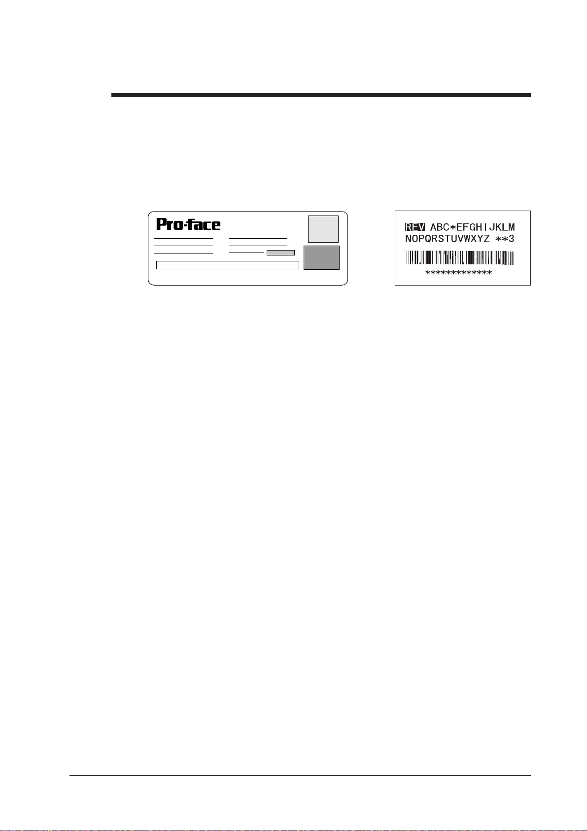
Revision Version
DIGITAL ELECTRONICS CORP.
REV ABC*EFGHIJKLMNOPQRSTUVWXYZ**345
The revision version can be determined by the identification label or revision
stickers that are placed on the main unit of the GP. The characters and numerals in
the "REV" area that are replaced with asterisks (*), or marked with a marker
indicate the revision version.
In the example below, the asterisks "*" are placed at positions "D", "1", and "2",
which indicates the revision version as "D, 1, 2".
Identification Label Revision Sticker
Preface
GP-2401/2501/2601 Series User Manual
16
The list below describes the documentation conventions used in this manual.
Documentation Conventions
*1 GP-PRO/PB III for Windows under Ver.6.22 does not support the following GP units.
If you install the add-on software, the above GP units will be available.
You can download the add-on software from Pro-face's web site.
(http://www.pro-face.com/)
Symbol Description
Indicatesimportantinformation orproceduresthatmustbefollowedfor
correctandrisk-freesoftware/deviceoperation.
*1 Indicatesuseful orimportantsupplementalinformation.
1) , 2) Indicatesstepsinaprocedure.Besuretoperform thesestepsinthe
ordergiven.
Referstousefulorimportantsupplemental information.
Providesuseful orimportantsupplemental information.
GP Screen
Editor
Indicatesthe GP-PRO/PBIIIforWindowsscreeneditorsoftware
(version6.10 orhigher*1).
For information on how to confirm the version, referto the “GP-PRO/PB
forWindowsOperationManual”,whichissupplied withtheGPscreen
editorsoftware.
PLC Abbreviation forProgrammableLogic Controller.
n:1 Indicatesa multi-linktypeconnection isused.
Ver.6.10 to Ver.6.1* Ver.6.20 to Ver.6.21
Notsuported
GP units
GP-2401T
GP-2501L
GP-2601T GP-2501L

GP-2401/2501/2601 Series User Manual 1-1
Be sure to follow these steps when creating projects for the GP unit.
1 Preparation Beforeusingthe GP, checkthatall required hardware is
presentandreadallspecification,wiring,andinstallation
information.
Chapter 2, "Specifications" and Chapter 3,
"InstallationandWiring"
2 Screen Design Create a sample screen and design a Tag layout, with
theScreenlayout sheets and Tag lists provided in the
Editorsoftware.
GP-PRO/PBIII for Windows Operation
Manual
3 Select GP and Using the input areas provided, select the GP and the
PLC types PLC types to be used.
GP-PRO/PBIII for Windows Operation
Manual GP-PRO/PBIII for Windows Tag
Reference Manual
4 Create Screen/ Run Setup the screenand tags in your screen editing
Screen Setup softwareaccording to your Screen Design.
GP-PRO/PBIII for Windows Operation
Manual and Tag Reference Manual
5 Transfer Screen Data Transfer the data from the Screen editor software on
your PC to the GP unit using the Data Transfer Cable.
GP-PRO/PBIII for Windows Operation
Manual
6 GP/HostConnection Setup the GP so thatit can receive data from the Host (PLC).
Chapter 6, "Initialize", and GP-PRO/
PBIII for Windows Device/PLC Connection Manual
7 Connect the GP Link the GP with the host (PLC) using the appropriate con-
nectioncable(differentcablesmaybenecessaryfordifferent
hosts), and then operate the unit.
GP-PRO/PBIII for Windows Device/
PLC Connection Manual
1.1 Prior to Operating the GP
Chapter
1 Introduction
1. Prior to Operating the GP
2. System Design
3. Accessories

Chapter 1 - Introduction
GP-2401/2501/2601 Series User Manual
1-2
GP RUN Mode Peripherals
Edit Mode
RUN Mode
Data Transfer
Cable
GPW-CB02
GP Unit
Printer Cable
PSM-PRCB00
Printer *3
(Commercial
type)
RS-232C Cable
GP410-IS00-O*7
Personal
Computer
Mitsubishi GPP
Software *4
CF Card
CA3-CFCALL/64MB-01, CA3-CFCALL/128MB-01,
CA3-CFCALL/256MB-01, CA3-CFCALL/512MB-01
Speaker*5,6
(Commercial
type)
RS-422 Cable
GP230-IS11-O*7
GP230-IS12-O*7
(for Multi-link cable)
RS-422 Connector
Terminal Adapter
GP070-CN10-O*7
Mitsubishi PLC FX-Series
Program Port I/F Cable
GP430-IP11-O
Mitsubishi PLC A-Series
Program Port I/F Cable
GP430-IP10-O
Host Controller
Mitsubishi PLC A,
Q, C, FX Series'
2 Port Adapter II
GP070-MD11
PLC etc.
2 Port Adapter II
Cable
GP070-MDCB11
(2)
(3)
(4)
(5) (6)
(7)
(8)
When using the Internal 2-Port feature
Bus
Conversion
Unit
PSL-CONV00*1
To an Ethernet Network*2
Expansion
Unit
(1)
Bar-Code Reader*5
(Limited to tested models)
ThefollowingdiagramrepresentsthestandarditemsconnectedtotheGP.
1.2 System Design
1.2.1 GP-2401/2501/2601 Series System Design
(8)
(8)
To each
Network
Communication
Unit
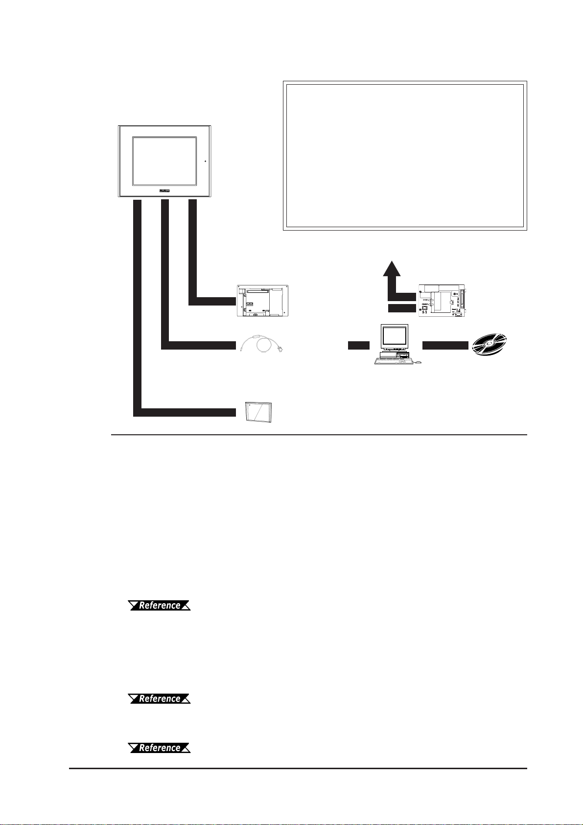
GP-2401/2501/2601 Series User Manual 1-3
Chapter 1 - Introduction
Data Transfer
Cable
GPW-CB02
GP Interfaces
(1) Expansion Bus
(2) Printer
(3) Tool Connector
(4) CF Card
(5) SIO
PLC Interfaces
(6) RS-232C Port
(7) RS-422 Port
(8) Programming Port
GP Edit Mode Peripherals
GP Unit
Personal
Computer *8 GP-PRO/PBIII
for Windows
software
*1GP-2501T, GP-2501S, GP-2501L and GP-2601T units can use this unit, however the
GP-2401T unit can not.
*2The optional Bus Conversion Unit and the Ethernet Unit are required to connect a GP-
2501/2601 Series to an Ethernet network.
*3Compatible with NECPC-PR201/PL , EPSON ESC/P24-J84(C), HP Laser Jet PCL 4
command printers,EPSON PM/Stylus (6-color ink), EPSON Stylus (4-color ink)
printers or their equivalent that are designed for MS-DOS.
Printers designed solely for Windows may not be used. Certain printers containing
both Windows and DOS drivers may be used. For details, please contact your printer's
manufacturer or sales outlet.
*4About certain types and models of PLC and software, see:
GP-PRO/PBIII for Windows Device/PLC Connection Manual (included
with the screen editor software)
*5 See Page 1-4 for recommended units.
*6 The optional Bus Conversion unit and Sound Output unit (Multi Unit S or Multi Unit
E) are required to connect the GP-2501/2601 Series to speakers.
*7Certain types and models of PLCs cannot be connected.
GP-PRO/PBIII for Windows Device/PLC Connection Manual (included
with the screen editor software)
*8Certain types and models of PCs cannot be connected.
GP-PRO/PBIII for Windows Operation Manual (included with the
screen editor software)
(3)
(4)
(1) Bus Conversion Unit
PSL-CONV00*1 Expansion
Unit
To an Ethernet Network*2
CF Card
CA3-CFCALL/64MB-01, CA3-CFCALL/128MB-01,
CA3-CFCALL/256MB-01, CA3-CFCALL/512MB-01
This manual suits for next models
2
Table of contents


