Digital Link DL3800 DS1 User manual

DL3800 DS1 Inverse
Multiplexer
User Guide
Part 098-10380-01 Rev J
February 1999

C
OPYRIGHT
Copyright © 1999, Digital Link Corporation
World copyright reserved. No part of this publication may be stored in a
retrieval system, transmitted, or reproduced in any way, including but not
limited to photocopy, photograph, magnetic, chemical, or other record,
without the prior agreement and written permission of Digital Link
Corporation.
Y
EAR
2000 C
OMPLIANCE
Digital Link warrants that products offered as generally available for sale
and shipped on or after February 1, 1999 will meet "Year 2000 compliant"
requirements. In addition, software released in and after 1998 meets the
Year 2000 compliance criteria. For more information on Year 2000
compliance, see our web site information at
www.dl.com
and click on the
Year 2000 compliance sticker.
P
RODUCT
L
IMITED
W
ARRANTY
Digital Link warrants to buyer that any unit shipped to buyer, under
normal and proper use, will be free from defects in material and
workmanship for a period of 24 months from the date of shipment to
buyer.
THE FOREGOING WARRANTY IS EXCLUSIVE AND IN LIEU OF ALL
OTHER WARRANTIES, EXPRESSED OR IMPLIED, INCLUDING, BUT NOT
LIMITED TO, ANY IMPLIED WARRANTIES OF MERCHANTABILITY OR
FITNESS FOR A PARTICULAR PURPOSE.
R
EMEDIES
AND
L
IMITATIONS
OF
L
IABILITY
All claims for breach of the foregoing warranty shall be deemed waived
unless notice of such claim is received by Digital Link during the applicable
warranty period and unless the items claimed to be defective are returned
to Digital Link within thirty (30) days after such claim. Failure of Digital
Link to receive written notice within the speciÞc period shall constitute a
waiver by buyer of any such claim irrespective of whether the facts giving
rise to such a claim shall have then been discovered or whether processing,
further manufacturing, other use or resale of such items shall have taken
place.
ii DL3800 DS1 Inverse Multiplexer User Guide—February 1999

Digital Link shall not be liable for failure to perform its obligations if such
results directly or indirectly from, or is contributed to by, any act of God or
of buyer; riot; Þre; explosion; accident; ßood; sabotage; epidemics; delays
in transportation; lack of or inability to obtain raw materials, components,
labor, fuel or supplies; governmental laws, regulations or orders; or labor
trouble, strike, or lockout (whether or not such labor event is within the
reasonable control of Digital Link); other circumstances beyond Digital
Link's reasonable control, whether similar or dissimilar to any of the
foregoing.
D
ISCLAIMER
Digital Link Corporation makes no representation of warranties with
respect to the contents of this document and speciÞcally disclaims any
implied warranties of merchantability or Þtness for any particular purpose.
Further, Digital Link Corporation reserves the right to revise this
publication and to make changes in it from time to time without obligation
to notify any person or organization of such revision or changes.
ISO C
OMPLIANCE
W
ARNING
The DL3800 complies with FCC Part 15 of the Federal Communications
Commission (FCC) Rules concerning radio frequency emissions for Class A
computing devices. The following section is required by the FCC.
C
AUTION
In accordance with FCC Part 15 section 15.21, changes or modiÞcations
made by the buyer that are not expressly approved by Digital Link
Corporation could void the buyerÕs authority to operate this equipment.
Products Manufactured Under
An ISO 9001 CertiÞed
Quality Management System
iii

This equipment has been tested and found to comply with the limits for a
Class A digital device, pursuant to Part 15 of the FCC Rules. These limits
are designed to provide reasonable protection against harmful interference
when the equipment is operated in a commercial environment. This
equipment generates, uses, and can radiate radio frequency energy and, if
not installed and used in accordance with the instruction manual, may
cause harmful interference to radio communications. Operation of this
equipment in a residential area is likely to cause harmful interference in
which case the user will be required to correct the interference at his own
expense.
C
USTOMER
I
NFORMATION
The equipment complies with Part 68 of the FCC Rules. You will Þnd the
label located on the bottom of the enclosure. This label contains the FCC
Registration Number and Ringer Equivalence Number (REN) for this
equipment. You must, upon request, provide this information to your
telephone company.
Incidence of harm: If your telephone equipment causes harm to the
telephone network, the telephone company may discontinue your service
temporarily. If possible, they will notify you in advance. But if advance
notice is not practical, you will be notiÞed as soon as possible. You will be
informed of your right to Þle a complaint with the FCC.
Rights of the telephone company: Your telephone company may make
changes in its facilities, equipment, operations or procedures that could
affect the proper functioning of your equipment. If they do, you will be
notiÞed in advance to give you an opportunity to maintain uninterrupted
telephone service.
NOTE:
As per the Voluntary Control Council for Interference by
Information Technology Equipment (VCCI), the DL3800 complies with
VCCI Class 1 ITE. This equipment is in the 1st Class category
(information equipment to be used in commercial and/or industrial
areas) and conforms to the standards set by the Voluntary Control
Council for Interference by Information Technology Equipment aimed at
preventing radio interference in commercial and/or industrial areas.
Consequently, when used in a residential area or in an adjacent area
thereto, radio interference may be caused to radios and TV receivers,
etc. Read the instructions for correct handling.
iv DL3800 DS1 Inverse Multiplexer User Guide—February 1999

Malfunction of the equipment: In the event this equipment should fail to
operate properly, disconnect the unit from the telephone line. Try using
another FCC approved telephone in the same telephone jack. If the trouble
does not persist and appears to be with this unit, disconnect the unit from
the telephone line and discontinue use of the unit until it is repaired.
Please note that the telephone company may ask that you disconnect this
equipment from the telephone network until the problem has been
corrected or until youÕre sure that the equipment is not malfunctioning.
v

vi DL3800 DS1 Inverse Multiplexer User Guide—February 1999

-vii
Table of Contents
Audience xvii
Organization xvii
Conventions xviii
Symbols xviii
Typography xix
Digital Link Technical Support xx
Returning a Unit xx
Send Us Your Comments xxi
Document Change Record xxi
Chapter 1, Quick Install Guide 1-1
Purpose 1-1
Configuration 1-1
Equipment Needed 1-1
Setup 1-2
Terminal Log on 1-2
Terminal Configuration 1-2
Unit Configuration 1-2
DTE Configuration 1-2
Network Configuration 1-3
Save Configuration 1-3
Chapter 2, Introduction 2-1
System Overview 2-1
DL3800 Functional Description 2-2
Signal Flow 2-3
T1 Port Mismatch Detection 2-4
Overhead Functions 2-5

Table of Contents -viii
DL3800 System Features 2-6
DL3800 System Benefits 2-6
Application 2-7
Chapter 3, Installation 3-1
DL3800 Installation Procedure 3-1
Mounting The DL3800 3-2
Rack Mounting 3-2
Desk Operation And Stacking 3-2
Power Cables And Connections 3-3
AC Power Connection 3-3
DC Power Connection 3-3
T1 Network Connection 3-4
DTE Cable And Connection 3-4
ASCII Terminal and SNMP Connection 3-5
Direct Connection 3-5
Modem Connection 3-5
Telnet Connection 3-5
Daisy Chaining 3-6
Chapter 4, Terminal Interface 4-1
Log In/Log Off 4-1
Terminal Operation Overview 4-2
General Menu Flow 4-2
Screen Description 4-2
Inverse Multiplexer Main Menu Commands 4-4
Select Local/Remote 4-4
Alarms and Status 4-5
Statistics 4-8
Event History 4-11
Configuration 4-12
Unit Configuration 4-13

Table of Contents -ix
DTE Configuration 4-16
Network Configuration 4-18
Network Thresholds 4-23
Save Configuration 4-24
System Utilities 4-24
Software Download 4-25
Software Download Options 4-27
RAM Software Options 4-28
Delete Entire Unit Configuration (revert to factory config) 4-29
Login Configuration 4-30
SNMP Configuration 4-33
In-Band SNMP to Remote 4-36
Save Configuration 4-36
Tests 4-36
DTE/Network Loopback 4-37
Payload Loopback 4-38
Line Loopback 4-38
Local Loopback 4-38
Manual Network Restoration 4-39
Logout 4-40
Chapter 5, Front Panel Interface 5-1
General 5-1
Display Overview 5-1
Button Overview 5-2
Exit Button 5-2
Up Arrow and Down Arrow Buttons 5-2
Enter Button 5-2
Front Panel LEDs 5-3
Access Levels And Protected Mode 5-4
Power Up And Reset 5-5

Table of Contents -x
Top Menu 5-5
Select Remote/Select Local 5-7
Display Menu 5-7
Node (Common Equipment) Status 5-8
DTE Status 5-9
NET (1-8) Status 5-9
NET (1 through 8) Statistics 5-9
Test Menu 5-11
DTE Tests 5-13
DTE/NET Loopback 5-13
Network Tests (1 through 8) 5-14
Payload Loopback 5-14
Line Loopback 5-15
Local Loopback 5-15
Configuration Menu 5-15
Node Configuration 5-17
DTE Configuration Menu 5-22
Network Config 5-22
NET N Config 5-23
Network Thresholds 5-24
Chapter 6, Diagnostics 6-1
Equipment Return And Repair 6-1
Running Diagnostic Tests 6-1
DTE/Network Loopback Test 6-2
LOCAL Loopback Test 6-2
Payload Loopback and Line Loopback Tests 6-3
Possible Sources of Problems 6-3
Troubleshooting the DL3800 6-3
Appendix A, SpeciÞcations A-1
T1 Network Interface A-1

Table of Contents -xi
External Clock Interface A-1
DTE Interface A-2
COMM Port A-2
NMS Port (SNMP) A-2
Front Panel A-3
Diagnostics A-3
Power A-3
Environmental A-4
Physical /Connectors A-4
Appendix B, Pinouts B-1
Terminal Connection B-1
DTE Connectors B-1
T1 Network Pin Assignments B-4
DB-25 to DE-9 Adapter Pinouts B-4
External Clock Connector Pin Assignments B-5
DTE Clock Rates B-6
Appendix C, Factory Default Settings B-1

Table of Contents -xii

-xiii
List of Figures
Figure 1-1 The DL3800 DS1 Inverse Multiplexer 1-1
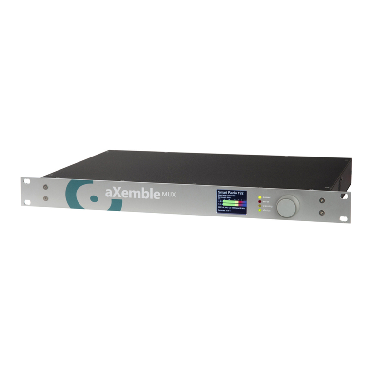
Figure 2-1 DL3800 Inverse Multiplexer 2-1
Figure 2-2 DL3800 Functional Schematic 2-4
Figure 2-3 Typical Application for DL3800 2-7
Figure 3-1 DL3800 Rear Panel 3-3
Figure 4-1 INVERSE MULTIPLEXER MAIN MENU 4-3
Figure 4-2 Main Menu with remote unit selected 4-5
Figure 4-3 ALARMS AND STATUS MENU 4-6
Figure 4-4 STATISTICS MENU 4-8
Figure 4-5 STATISTICS MENU (Screen #1) 4-9
Figure 4-6 STATISTICS MENU (Screen #2) 4-10
Figure 4-7 EVENT HISTORY MENU 4-12
Figure 4-8 CONFIGURATION MENU 4-13
Figure 4-9 UNIT CONFIGURATION MENU 4-14
Figure 4-10 DTE CONFIGURATION MENU 4-16
Figure 4-11 Network ConÞguration Screen (DSX-1 Mode) 4-19

List of Figures -xiv
Figure 4-12 Network Thresholds ConÞguration 4-23
Figure 4-13 SYSYTEM UTILITIES MENU Figure 4-25
Figure 4-14 SOFTWARE DOWNLOAD MENU 4-25
Figure 4-15 LOGIN CONFIGURATION MENU 4-31
Figure 4-16 SNMP CONFIGURATION MENU 4-33
Figure 4-17 TESTS MENU 4-37
Figure 4-18 Loopbacks Within the DL3800 4-38
Figure 4-19 MANUAL NETWORK RESTORATION MENU 4-39
Figure 5-1 Front Panel Top Level Menu 5-6
Figure 6-1 TESTS MENU 6-2

-xv
List of Tables
Table 4-1 Main Menu 4-4
Table 4-2 Alarms and Status 4-6
Table 4-3 STATISTICS MENU Error Types 4-10
Table 4-4 Alarm Level 4-11
Table 4-5 Node Configuration Options 4-14
Table 4-6 DTE CONFIGURATION MENU Options 4-16
Table 4-7 NETWORK CONFIGURATION MENU Options 4-19
Table 4-8 Login Configuration Options 4-32
Table 4-9 SNMP Configuration Options 4-33
Table 5-1 Front Panel LEDs 5-3
Table 5-2 NET Statistics Menu Information Display 5-9
Table 5-3 NET Statistics Items 5-10
Table 5-4 CONFIGURATION MENU Items 5-16
Table 5-5 NODE CONFIGURATION MENU Items 5-19
Table 5-6 NET THRESHOLD Options and Values 5-25
Table 6-1 Troubleshooting (1 of 5) 6-4

List of Tables -xvi
Table B-1 COMM and NMS Port Pin Assignments B-1
Table B-2 HSSI DTE Connector Pin Assignments B-1
Table B-3 DB-25 to V.35 DTE Connector Pin Assignments B-2
Table B-4 DB-25 to RS-449 DTE Connector Pin Assignments B-3
Table B-5 Network Pin Assignments B-4
Table B-6 DB-25 to DE-9 Pinouts B-4
Table B-7 External Clock Pinouts B-5
Table B-8 DTE Clock Rates B-6
Table C-1 Unit Settings B-1
Table C-2 DTE Settings B-1
Table C-3 Network Settings B-2
Table C-4 Network Threshold Settings B-2
Table C-5 SNMP Configuration Settings B-2
Table C-6 Test Settings B-3

-xvii
Preface
The DL3800 DS1 Inverse Multiplexer User Guide provides the information
you need to install, test, operate, and manage the DL3800.
AUDIENCE
This guide is prepared for network managers and technicians who are
responsible for the installation of LAN-to-WAN equipment, and who are
thoroughly familiar with the network topology in which the DL3800 is
expected to operate.
ORGANIZATION
Chapter 1, ÒQuick Install Guide,Ó provides a concise installation procedure
for most applications.
Chapter 2, ÒIntroduction,Ó provides a description of the DL3800 system
architecture, a discussion of features and beneÞts, and a sample
application.
Chapter 3, ÒInstallation,Ó provides guidelines for placing and securing the
DL3800 in the operation site. Use this chapter to Þnd out about command
tools, system access, and basic conÞguration.
Chapter 4, ÒTerminal Interface,Ó shows how to monitor and manage the
DL3800 using a VT100 terminal.
Chapter 5, ÒFront Panel Interface,Ó shows how to monitor and manage the
DL3800 using the front panel.
Chapter 6, ÒDiagnosticsÓ provides guidelines for troubleshooting the
DL3800.
Appendix A, ÒSpeciÞcations,Ó provides the electrical, physical, and
networking characteristics of the DL3800.
Appendix B, ÒPinouts,Ó details connector and pin assignments for the
DL3800.
Appendix C, ÒFactory Default Settings,Ó lists factory defaults for for the
DL3800.

-xviii DL3800 DS1 Inverse Multiplexer User Guide—February 1999
CONVENTIONS
This section describes the conventions used to delineate speciÞc types of
information throughout Digital Link user guides.
Symbols
Symbols denote text that requires special attention. The information
contained alongside a symbol corresponds to one of four levels of severity:
NOTE: Follow guidelines in this, or the previous, paragraph to use the
Digital Link product more effectively.
CAUTION: Follow guidelines in this, or the previous, paragraph to
avoid equipment damage or faulty application.
WARNING: Follow the instructions in this, or the previous, paragraph
to avoid personal injury.
ELECTRO-STATIC DISCHARGE — CAUTION: Follow the instructions in
this, or the previous, paragraph to avoid the discharge of static
electricity, and subsequent damage to the equipment.

Preface -xix
Typography
Digital Link manuals delineate the names of Þles, commands, and actions
by using the fonts and typefaces described in the following table:
Typeface or
Symbol Purpose Example
Courier Font
AaBbCc123
The names of commands, files, and
directories, as well as on-screen
computer output.
Edit your.login Þle.
Use ls -a to list all Þles.
machine_name% You have mail.
Courier
Font, Bold
AaBbCc123
The input you provide, as contrasted
with on-screen computer output. machine_name% su
Keystrokes that you must provide to
use the application. Press Ctrl-L to refresh the screen.
Palatino Font,
Italic
AaBbCc123
Command-line placeholder that you
replace with a real name or value. To delete a Þle, type rm Þlename
Book titles, new words or terms, or
words that need to be emphasized. Refer to Chapter 6 in the User Guide.
These are called class options.
You must be logged in as root to
access this directory.
▼
Zapf Dingbats
Font
Symbol that denotes a single-step
procedure or task. Procedures
requiring more than one task are
numbered.
Palatino Font,
Bold Blue,
Underscore
AaBbCc123
Hyperlinks in the table of
contents.When viewing the Portable
Document Format (PDF) version of the
user guide, you can click on one of
these to jump directly to the selected
subject matter.
Palatino Font,
Blue
AaBbCc123
or
AaBbCc123
Hyperlinks throughout general text.
HelveticaBold Denotes actual markings on front or
back panels. Attach the cable to the TERMINAL
port

-xx DL3800 DS1 Inverse Multiplexer User Guide—February 1999
DIGITAL LINK TECHNICAL SUPPORT
If you should experience difÞculty with the setup and/or operation of your
Digital Link equipment, the Digital Link Technical Support staff can assist
you at any time.
Before you place a call for help, use the form provided at the end of this
Preface to assemble the information that your technical support
representative is likely to request.
RETURNING AUNIT
Use the following procedure if you need to return a unit for service or
repair,
1. Contact the Digital Link Customer Service Department at
(408)745-4200,orviae-mailat[email protected],orfaxarequestto(408)
745-4240 to obtain an ERA (Equipment Return Authorization)
number.
2. Packagetheunitcarefullyand,beforesealingtheshippingcarton,
include any information you can provide about the problems you
are currently experiencing with the unit.
3. Attach an address label to the shipping carton. Be sure to include
the ERA number:
Telephone (408) 745-4200
FAX (408) 745-4240
Email suppor[email protected]
Internet www.dl.com
Customer Service Department
Digital Link Corporation
217 Humboldt Court
Sunnyvale, CA 94089
ERA # ___________
Table of contents
Other Digital Link Multiplexer manuals
