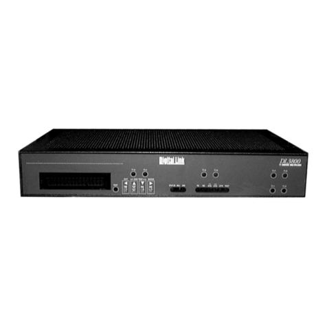
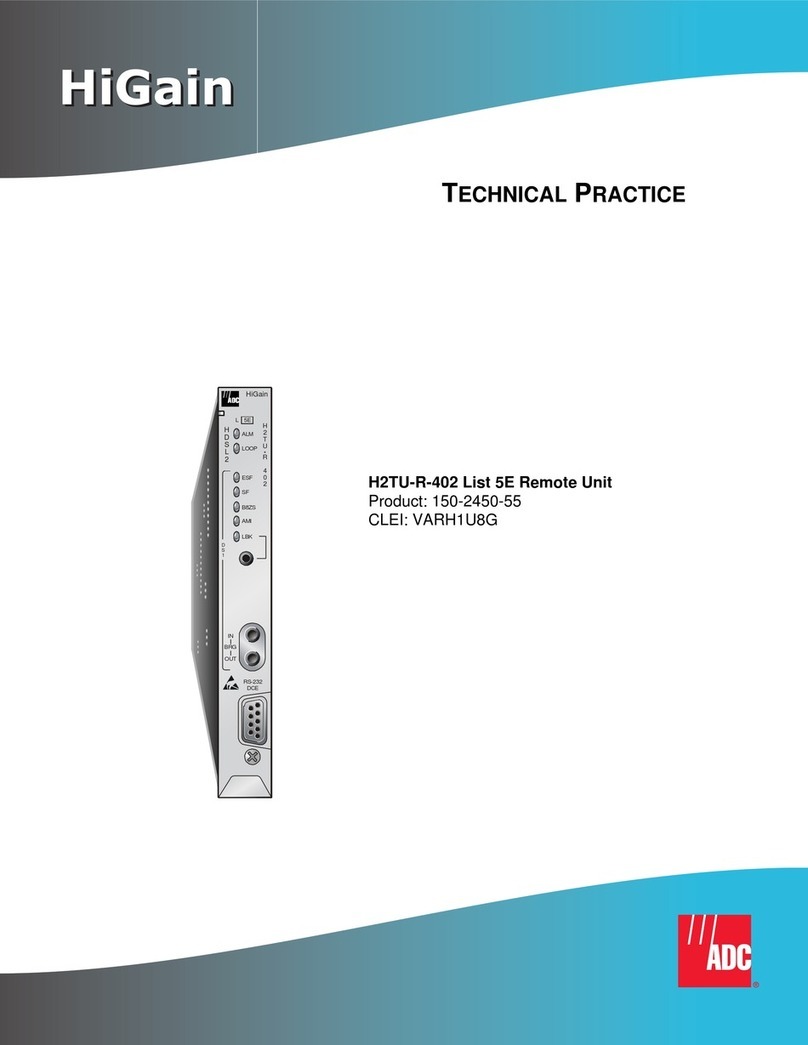
Digital Link DL600E E1 User manual

DL600E E1
Data Multiplexer
UserÕs Guide


iii
Copyright © 1997, Digital Link Corporation
World copyright reserved. No part of this publication may be stored in a retrieval
system, transmitted, or reproduced in any way, including but not limited to photocopy,
photograph, magnetic, chemical, or other record, without the prior agreement and
written permission of Digital Link Corporation.
Digital Link Corporation
217 Humboldt Court
Sunnyvale, California 94089
(408) 745-6200
FAX (408) 745-6250
www.dl.com
098-00961-01 Rev. A

iv
Product Limited Warranty
Digital Link warrants to buyer that any unit shipped to buyer, under normal and proper
use, will be free from defects in material and workmanship for a period of 24 months
from the date of shipment to buyer. This warranty will not apply to any unit repaired by
anyone other than the Digital Link or its authorized agent.
THE FOREGOING WARRANTY IS EXCLUSIVE AND IN LIEU OF ALL OTHER
WARRANTIES, EXPRESSED OR IMPLIED, INCLUDING, BUT NOT LIMITED
TO, ANY IMPLIED WARRANTIES OF MERCHANTABILITY OR FITNESS FOR
A PARTICULAR PURPOSE.
Remedies and Limitations of Liability
A
ll claims for breach of the foregoing warranty shall be deemed waived unless notice
of such claim is received by Digital Link during the applicable warranty period and
unless the items claimed to be defective are returned to Digital Link within thirty (30)
days after such claim. Failure of Digital Link to receive written notice of any such
claim irrespective of whether the facts giving rise to such a claim shall have been
discovered or whether processing, further manufacturing, other use or resale of such
items shall have taken place.
Buyer's exclusive remedy, and Digital Link's total liability, for any and all losses and
damages arising out of any cause whatsoever, (whether such cause is based in contract
negligence, strict liability, other tort or otherwise) shall in no event exceed the repair
price of the unit from which such cause arises. In no event shall Digital Link be liable
for incidental, indirect, special or consequential damages resulting from any such
cause event if Digital Link is aware of the possibility of such damages. Digital Link
may, at its sole option, either repair or replace defective goods or work, and shall have
no further obligation to buyer. Return of the defective items to Digital Link shall be
at buyer's risk and expense.
Digital Link shall not be liable for failure to perform its obligations if such results
directly or indirectly from, or is contributed to by, any act of God or of buyer; riot;
Þre; explosion; accident; ßood; sabotage; epidemics; delays in transportation; lack of
or inability to obtain raw materials, components, labor, fuel or supplies; governmental
laws, regulations or orders; or labor trouble, strike, or lockout (whether or not such
labor event is within the reasonable control of Digital Link); other circumstances
beyond Digital Link's reasonable control, whether similar or dissimilar to any of the
foregoing.
Digital Link Corporation
217 Humboldt Court
Sunnyvale, California 94089
(408) 745-6200
FAX (408) 745-6250

v
Disclaimer
Digital Link Corporation makes no representation of warranties with respect to the
contents of this document and speciÞcally disclaims any implied warranties of
merchantability or Þtness for any particular purpose. Further, Digital Link Corporation
reserves the right to revise this publication and to make changes in it from time to time
without obligation to notify any person or organization of such revision or changes.
ISO Registration
Q
U
A
L
I
T
Y
A
S
S
U
R
E
D
F
I
R
M
ISO
9001
Products Manufactured Under
An ISO 9001 Certified
Quality Management System

vi
Regulatory Compliance Standards
To maintain EMC Class B(CE Label) compliance, shielded cables should be used with
the unit.
The Digital Link DL600E module complies with
¥ CE MARK
¥ BABT NTR4
¥ Austel TS016
¥ Swedish SS636334
¥ German M†9a/b
¥ Australian AS 3260
¥ FCC part 15 Class A
¥ UL 1950 3rd Edition
¥ CAN/CSA C22.2. No. 950-95 3rd Edition
European harmonized standards:
¥ 73/23/EEC
¥ 91/31/EEC
¥ 89/336/EEC
¥ 93/68/EEC
¥ 91/263/EEC
¥2 Mbit/s G703 (E1) interface against UK speciÞcation NTR4 (75 ohm unbal-
anced)
¥2 Mbit/s G.703 (E1) interface against CTR12 (120 ohm balanced, unstructured)
including protection test
¥2Mbit/s G.703 (E1) interface against TBR13 (120 ohm balanced, structured)
including protection tests.
Under 89/336/EEC, as amended by 92/31/EEC and 93/68/EEC, the DL600E was tested
in accordance with EN50081-1 (1995) and EN50082-1 (1994) to the following stan-
dards: EN55022 Level B, IEC 1000-4-2, ENV50140, ENV50141, IEC 1000-4-4,
ENV50142, EN61000-4-8, and EN61000-4-11.
Under 73/23/EEC as amended by 93/68/EEC, the DL600E was tested to IEC 950 (1994)
3rd edition; EN 60950 (1992) 3rd edition. Under 91/263/EEC, this unit complies with the
Pan-european requirements set forth in CTR 12 and TBR 13.
Under 91/263/EEC this product complies with the requirements of Annex III for Pan-
European approval under CTR 12 and TBR 13 for 120 ohm operation. This information
is contained in a report prepared by KTL. This report was submitted to BABT with a
reference number: 1MST0400 and carries the BABT logo with the approval number:
AA607035.
168

Table of Contents
Preface xvii
About this Manual xviii
Audience xviii
Organization xviii
Symbols xix
Typographic Conventions xix
Digital Link Technical Support xx
Send Us Your Comments xxi
When Returning a Unit xxi
Chapter 1 About the DL600E Unit 1-1
Introducing the DL600E Unit 1-2
DL600E Features 1-4
About the Telnet Utility 1-5
Applications 1-5
Chapter 2 Installing the DL600E Unit 2-1
Preparing for the Installation 2-2
Checking the Equipment 2-2
Equipment Model Numbers 2-3
Gathering Information 2-3
About the Power Supply 2-4
Installing the DL600E in a 19Ó or 23" Rack 2-4
Installing the DL600E Unit Using AC Power 2-4
Installing the DL600E Unit Using DC Power 2-5
To Connect the DL600E Unit to DC Power 2-5
Connecting to a DTE Device and the Network 2-7

viii
DL600E E1 Data Multiplexer UserÕs Guide
Chapter 3 Configuring the DL600E Unit 3-1
Preparing to Configure 3-2
Keeping a Record 3-2
Connecting an ASCII Terminal 3-2
Logging on to the DL600E Terminal Interface 3-6
Before You Begin 3-9
Overview of the Configuration 3-9
Setting the Unit ID, Date and Time 3-10
Configuring the E1 Network and AUX E1 Port Parameters 3-11
Downloading New Software 3-13
System Messages and Error Indicators 3-14
Configuring the Data Port 3-16
Allocating Timeslots 3-17
Two Allocation Methods 3-17
Configuring for SNMP 3-21
SNMP Parameters 3-21
Configuring Two Levels of Access Rights 3-23
Superuser Access Rights 3-23
Assigning User Passwords 3-23
Configuring Alarm Conditions 3-24
How the DL600E Unit Reports Alarms 3-24
How Alarms Reports Are Displayed 3-24
Configuring Alarms 3-25
Alarm Conditions and System Action 3-27
Chapter 4 Monitoring and Managing the DL600E Unit 4-1
Introduction 4-2
Logging on to the DL600E 4-2
User Access Rights 4-2
Logging on from a Terminal 4-3
Logging On Using a Telnet Connection 4-5
Logging Off 4-6
Monitoring Status 4-6
Menu-2 Data DTE Status 4-10
Displaying Performance Reports 4-11

ix
Chapter 5 Using the Front Panel Interface 5-1
Introduction 5-2
What You CanÕt Do From the Front Panel Interface 5-2
Front Panel Description 5-3
How to Navigate the Front Panel Interface 5-3
Display Description 5-4
Editing a Parameter 5-6
Preparing for the Initial Configuration 5-7
Required Information 5-7
Keeping a Record 5-7
Configuring the Unit and Network Parameters 5-8
The UNIT CONFIG Submenu 5-9
Configuring the Data Ports 5-14
Allocating Timeslots 5-14
Displaying the Timeslot Allocation 5-15
The TIMESLOT CONFIG Menu 5-15
Allocating Timeslots Contiguously Example 5-16
Configuring for SNMP 5-18
Using the MONITOR Menu 5-19
Monitoring the Local and Remote Units 5-19
Using the TEST Menu 5-20
Starting and Ending a Test 5-20
Sending a Test Pattern 5-22
Running TEST PATTERN on a Fraction of the Bandwidth 5-24
LAMP Test 5-25
Chapter 6 Diagnosing the DL600E Unit 6-1
Running Diagnostic Tests 6-2
The Diagnostics Menu 6-3
Running a Test from Menu-9 Diagnostics 6-4
Test Parameters 6-4
Test Types 6-6
Self Test 6-6
Loop DTE Test 6-6
Loop NET Test 6-7
Loop Payload Test 6-8
Loop Up Remote and Loop Down Remote Tests 6-8
Running Tests from the Front Panel 6-10

x
DL600E E1 Data Multiplexer UserÕs Guide
Appendix A DL600E Technical Specifications A-1
Technical Specifications A-2
SNMP A-3
Terminal Supported A-4
Equipment Grounding Conductor A-4
Front Panel LEDs and Buttons A-4
Factory Default Configuration A-7
Configuration Worksheet A-8
DL600E Model Numbers A-9
Appendix B Connector and Pin Assignments B-1
E1 Network Pin Assignments B-2
DL600E-to-Equipment Pin Assignments B-3
DB25-to-DC-37 (RS449) Data Port Connector Pin Assignments B-5
DB25-to-M-34 (V.35) DCE Connector Pin Assignments B-6
DB25-to-DC-37 (RS449) DCE Connector Pin Assignments B-7
Communication Port Pin Assignments B-8
DE9-to-DB25 Adapter Pin Assignments B-9
DB25-to-DE9 Adapter Pin Assignments B-9
Glossary
Index

Table of Figures
Figure 1-1 Front View of the DL600E Unit 1-3
Figure 1-2 Back View of the DL600E Unit 1-3
Figure 2-1 DL600E Rear Panel Showing Power Connections 2-4
Figure 2-2 DL600E Rear Panel Showing Network Connections 2-7
Figure 3-1 Comm Port on the Back Panel 3-4
Figure 3-2 Menu-4 Main Configuration 3-10
Figure 3-3 Menu-5 Data Port Configuration 3-16
Figure 3-4 Menu-6 Timeslot Configuration 3-18
Figure 3-5 Menu-0 SNMP Config. 3-21
Figure 3-6 Menu-7 Alarm I 3-25
Figure 3-7 Menu-8 Alarm II 3-28
Figure 4-1 Menu-1 Main Status 4-6
Figure 4-2 Menu-2 Data DTE Status 4-10
Figure 4-3 Carrier Registers, 24 hour Detail 4-11
Figure 5-1 Front Panel Interface 5-3
Figure 6-1 Menu-9 Diagnostics 6-3
Figure 6-2 Loop DTE Test 6-7
Figure 6-3 Loop NET Test 6-7
Figure 6-4 Loop Payload Test 6-8
Figure 6-5 Loop Up Remote Test 6-9

xiv
DL600E E1 Data Multiplexer UserÕs Guide

Table of Tables
Table 3-1 DL600E Software Download Errors 3-15
Table 3-2 DL600E Alarm Conditions 3-24
Table 3-3 DL600E Alarm Conditions and System Action 3-27
Table 6-1 Self Test Error Indicators 6-6

xvi
DL600E E1 Data Multiplexer UserÕs Guide

Preface
¥ About this Manual xviii
¥ Digital Link Technical Support xx
¥ Send Us Your Comments xxi
¥ When Returning a Unit xxi
Ensemble Encore UserÕs Guide

xviii
DL600E E1 Data Multiplexer UserÕs Guide
About this Manual
The
DL600E E1 Data Multiplexer UserÕs Guide
provides information to
install, conÞgure, test, operate and manage the DL600 Encore E1 Data
Service Unit.
Throughout this manual, ÒDL600E unitÓ is used to refer to the DL600
Encore E1 Data Service unit.
Audience
This guide is intended for experienced network managers and technicians
who install LAN to WAN equipment. Users should be thoroughly familiar
with the network topology in which the DL600E will operate.
Organization
This guide contains six chapters, two appendices, a glossary and an index.
Chapter 1
, ÒAbout the DL600E UnitÓ provides a description of the
DL600E unit and its features.
Chapter 2
, ÒInstalling the DL600E UnitÓ provides hardware requirements
and instructions for installing the DL600E unit.
Chapter 3
, ÒConÞguring the DL600E Unit from a TerminalÓ shows how to
conÞgure the DL600E unit for a network environment.
Chapter 4
, ÒMonitoring and Managing the DL600E UnitÓ provides
instructions for managing and monitoring DL600E performance.
Chapter 5
, ÒUsing the Front Panel InterfaceÓ explains how to conÞgure
the DL600E unit from the Front Panel Interface.
Chapter 6
, ÒDiagnosing the DL600E UnitÓ provides instructions for
diagnosing and troubleshooting the DL600E Unit.
Appendix A
, ÒDL600E Technical SpeciÞcationsÓ provides basic data
speciÞcations, parameters, and the factory default conÞguration for the
DL600E unit.
Appendix B,
ÒDL600E Connector and Pin AssignmentsÓ provides
network, channel 1, data port, comm port and adapter pin assignments for
the DL600E unit.
Glossary,
provides a glossary of terms used in this manual.
Index,
provides an index of the manual.

Preface
xix
Symbols
The following symbol means it is very important to follow instructions
carefully:
Warning!
The following symbol means you must follow the instructions carefully
to avoid possible risk of electrical shock:
Warning!
Typographic Conventions
The procedures in this guide are offset with horizontal lines and each
step in a procedure is numbered. Single step procedures are not
numbered.
This guide uses the following typographic conventions:
¥ Key words appear in boldface to draw your attention. For
example:
Type in the
password
and press
Return
.
D
Note:
CTS (pin 8)
must
be connected between DL600E
units, but it
must not
be connected to the terminal.
¥ SigniÞcant terms, when they appear for the Þrst time also
appear in boldface. For example:
Special instructions for installing the DL600E unit with
DC
power
are given at the end of this section.
¥ Names of menus, Þelds, and system prompts appear in italics.
For example:
In
Menu 8 Alarm II,
Connection
is set to
Modem
and two differ-
ent valid telephone numbers are entered in
Phone Number 1
and
Phone Number 2
.
¥ Two keys separated by a hyphen mean you hold down the Þrst
key while pressing the second key (unless indicated otherwise).
Press
Ctrl-x
Þve timesÑmeans hold down the
Ctrl
key and press
x
Þve times.

xx
DL600E E1 Data Multiplexer UserÕs Guide
Digital Link Technical Support
If you encounter a problem with the DL600E unit, prepare the
following information and contact Digital Link Technical Support.
1
What is the software revision?
2
What is the hardware revision?
3
How is the unit conÞgured?
4
When was the unit conÞguration last changed? How?
5
What is connected to the unit (routers, test equipment, and so on)?
6
What operation was in progress when the failure occurred?
7
What was the state of the LEDs on the front panel when the failure
occurred?
8
What methods did you use in trying to resolve the problem?
9
Is the problem repeatable? If so, how?
10
Are the cables attached securely to the unit?
11
Are the cables shielded?
12
What is the unitÕs clock source?
13
Who can be contacted to discuss the problem?
14
What is the unit password(s)?
15
What information is on the conÞguration, error statistics and event
history display screens at the time of the error? (Please provide a
hard copy capture of the screens.)
Tech Support U.S.A.:
Company FAX:
Email:
(408) 745-4200
(408) 745-6250
Hours:
24-hour service, 7 days a week
Tech Support UK: +44 171 244-7660

Preface
xxi
Send Us Your Comments
We want to know if this manual meets your needs.
Help us improve our service by sending us your comments. Tell us what
parts of the manual work for you, what parts do not, and what is missing.
You can send your comments and suggestions to:
¥ Digital Link Technical Publications facsimile: (408) 745-6250
or
¥ Digital Link E-mail: techpubs@dl.com
When Returning a Unit
To return a unit for service or repair, call the Customer Service
Deptartment at Digital Link Þrst, ((408) 745-4200 in the U.S.A. or +44
171 244-7660 in the U.K ) to obtain an
ERA
number
(Equipment Return
Authorization number).
Carefully package the unit with the ERA number on the address label
and enclose a note describing the problem. Send it to the address below.
Customer Service Department
DIGITAL LINK CORPORATION
217 Humboldt Court
Sunnyvale, California 94089

xxii
DL600E E1 Data Multiplexer UserÕs Guide
This manual suits for next models
1
Table of contents
Other Digital Link Multiplexer manuals
Popular Multiplexer manuals by other brands

Optical Systems
Optical Systems OSD860 SERIES Operator's manual
Net to Net Technologies
Net to Net Technologies AIM24000 user guide
Siemens
Siemens 7KE6000-8AH /CC operating instructions
Lucent
Lucent DDM-2000 OC-3 User and service manual
American Fibertek
American Fibertek MRT-860SL instruction manual
Raisecom
Raisecom RC802-240B user manual
