Digital Lumens DLA-R User manual

DLA Sensor
INSTALLATION INSTRUCTIONS
PRODUCT SAFETY
!
Digital Light Agent™(DLA) hardware must be installed in accordance with the applicable installation code by a person
familiar with the construction and operation of the product and the hazards involved.
To avoid risk of electrical shock, disconnect power before installing, wiring, or servicing DLA hardware.
! DonotusextureorDLAhardwareifthehousing,sensoropticorwiresaredamaged.
!
Do not apply paint, lubricants or other coatings to the DLA housing.
!
Use a dry cloth to clean the DLA housing and sensor optic.
GETTING STARTED
OVERVIEW
The DLA system transforms xtures from third-party manufacturers into an intelligent light with high-performance sensors, power
metering, full-range dimming, and software optimization capabilities.
There are two categories of DLA components: DLA sensors and DLA adapters.
• DLA sensors measure occupancy and ambient light. They also control connected xtures through a direct link with Philips SR
(Sensor Ready) drivers, DALI drivers, or through 0-10 V adapters (for older 0-10 V LED drivers). DLA sensors communicate
wirelessly with the LightRules system to receive commands and send data.
• DLA adapters measure xture power consumption. They also convert the digital commands from DLA sensors into an analog
0-10 V signal for use with 0-10 V dimming LED drivers.
Note that this document covers DLA sensors. Please refer to the DLA Adapter Installation Instructions for adapter setup.
SENSOR TYPES
DLA-R (Recessed Mount)
Use the DLA-R when you want to blend the sensor into an environment by mounting ush to a junction box or
a ceiling tile.
DLA-E (Philips EvoKit)
The DLA-E is designed to install in the mounting slot of the Philips EvoKit SR retrot kit.
DLA-S (Surface Mount)
Featuring an IP65 rating, use the DLA-S in challenging environments. DLA-S mounts to a ceiling surface or
NEMA 4 or weatherproof junction box.
DLA-I (Integrated Mount)
The DLA-I mounts directly to into any third-party xture — the housing mounts inside and the lens assembly
extends externally.
HELPFUL HINTS
• Install the DLA sensor in a manner so as to provide a clear eld of view for the lens.
• Do not mount the DLA sensor within 5 ft (1.5 m) of an air vent.
• Consult the DLA specication sheets for detail regarding mounting heights and occupancy sensor coverage patterns.
2 | DLA SENSOR INSTALLATION INSTRUCTIONS
Step One: Install DLA Hardware
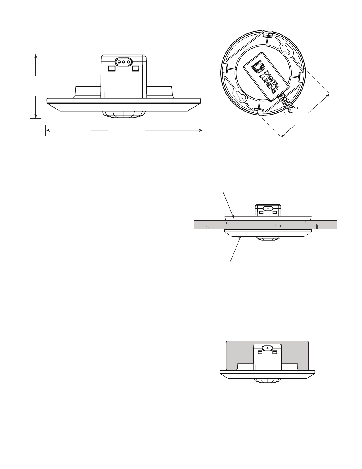
DLA-R Installation
METHOD ONE: CEILING TILE INSTALLATION
a. Review the DLA-R dimensional drawings, above.
b. Remove and put aside the extra serial number label.
c. Remove the plastic bezel.
Hint: Place your thumb on the notch in the bezel and pull away
to release.
d. Using the metal mounting plate as a template, trace the inner
prole and the screw holes and then cut the ceiling tile using
an appropriate saw.
e. Insert the sensor housing up through the hole in the ceiling
tile, place the mounting plate on the back of the ceiling tile
around the sensor housing, and then secure using the (2x)
supplied Phillips screws.
Note: Place the at side of the collar against the tile.
f. Replace the bezel.
g. Make power and data connections (see Step Two on page 6).
METHOD TWO: 4-INCH ROUND JUNCTION BOX INSTALLATION
a. Review the DLA-R dimensional drawings, above.
b. Remove and put aside the extra serial number label.
c. Remove the plastic bezel.
Hint: Place your thumb on the notch in the bezel and pull away
to release.
d. Discard the metal mounting plate.
e. Make power and data connections (see Step Two on page 6).
f. Insert the sensor housing into the junction box and then
secure using the (2x) supplied Philips screws.
g. Replace the bezel.
1.9 in
4.7 cm
4.6 in
11. 6 cm
3.5 in
8.9 cm
1
Ceiling Tile Mount
Junction Box Mount
Bezel
Mounting Plate
DIGITAL LUMENS | 3
Step One: Install DLA Hardware, cont.
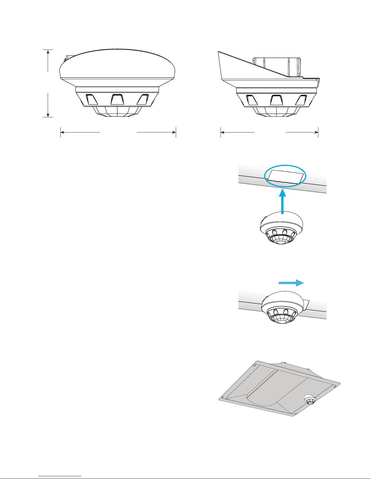
DLA-E Installation
1.9 in
4.7 cm
3.3 in
8.3 cm
3.0 in
7.6 cm
STANDARD INSTALLATION METHOD
a. Remove and put aside the extra serial number label.
b. Make power and data connections (see Step Two on page 7).
c. Insert the sensor housing up through the existing cutout
in the Philips EvoKit SR xture.
d. Slide the sensor housing sideways until it ‘snaps’ into place.
e. Install the Philips EvoKit SR xture as per the manufacturer’s
instructions.
Finished Assembly
4 | DLA SENSOR INSTALLATION INSTRUCTIONS
Step One: Install DLA Hardware
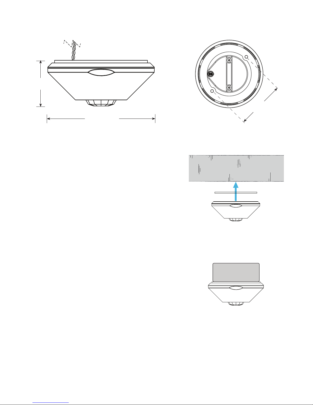
DLA-S Installation
2.1 in
5.3 cm
4.9 in
12.4 cm
3.5 in
8.9 cm
Important Note
The DLA-S is IP65-rated and designed for use in damp or wet
environments. Ensure that the included mounting gasket is
intact before installation.
METHOD ONE: CEILING INSTALLATION
a. Review the DLA-S dimensional drawings, above.
b. Remove and put aside the extra serial number label.
c. Remove the plastic bezel.
Hint: Squeeze the two at areas on the edge of the bezel and
pull away to release.
d. Cut a .5 in (7 mm) or greater hole in the ceiling panel and run
the power and data wires through the opening.
e. Make power and data connections (see Step Two on page 8).
f. Secure the housing using suitable fasteners (supplied by installer).
g. Replace the bezel.
METHOD TWO: 4-INCH IP65 JUNCTION BOX INSTALLATION
a. Review the DLA-S dimensional drawings, above
b. Remove and put aside the extra serial number label.
c. Remove the plastic bezel.
Hint: Squeeze the two at areas on the edge of the bezel and
pull away to release.
d. Make power and data connections (see Step Two on page 6).
e. Secure the housing to an IP65 round NEMA 4 or
weatherproof enclosure using the (2x) supplied Philips screws.
f. Replace the bezel.
Ceiling Mount
Junction Box Mount

DIGITAL LUMENS | 5
Step One: Install DLA Hardware, cont.
DLA-I Installation
2.44 in
6.2 cm
2.44 in
6.2 cm
1.6 in
4.0 cm
.9 in
2.3 cm
.9 in
2.3 cm
1.3 to 1.4 in
3.3 to 3.6 cm
1
.125 in
3.18 mm
Maximum
Gasket
Hex Nut
Fixture
Important Note
The DLA-I is designed to install within a third-party
xture housing, with the sensor optic extending externally.
Be sure to install the gasket and hex nut in the correct
order, as shown to the right.
STANDARD INSTALLATION METHOD
a. Review the DLA-I dimensional drawings, above.
b. Remove and put aside the extra serial number label.
c. Detach the lens assembly by turning it counter-clockwise.
d. Remove the hex nut.
e. The DLA-I requires a 1 in trade-size knockout (1.3 to 1.4
in / 3.3 to 3.6 cm hole) for proper mounting and sealing.
f. Install the DLA-I module inside the xture housing, with
the threaded nipple extending outside the xture housing
through the opening created in the previous step.
g. Secure the housing using the supplied hex nut. Tighten
the hex nut.
h. Re-connect the lens assembly, turning it clockwise the
lens assembly stops rotating.
i. Make power and data connections (see Step Two on
page 6).
j. Install the third-party xture as per the manufacturer’s
instructions.
6 | DLA SENSOR INSTALLATION INSTRUCTIONS
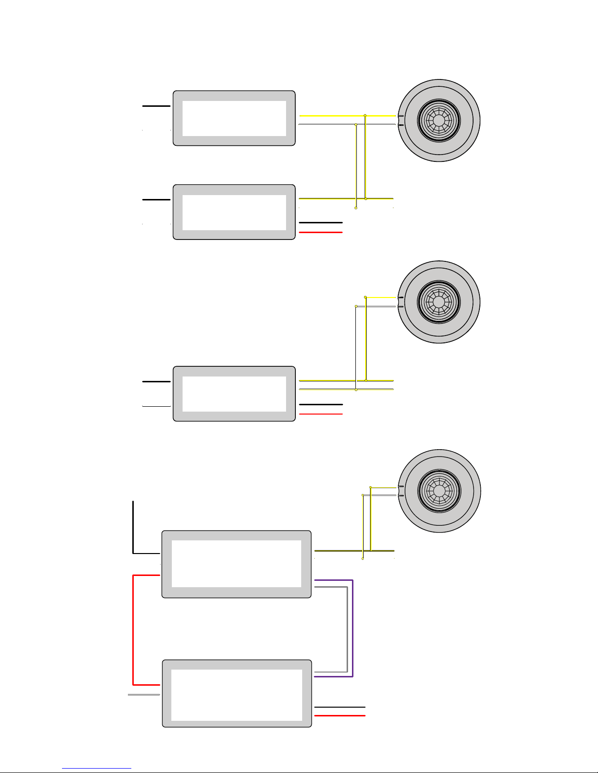
Step Two: Make Power and Data Connections
DLA-R, DLA-S and DLA-R Wiring Examples (DLA-R shown)
0-10 VDC Wiring
DC – (Black)
DC + (Red)
+
-
(to LEDs)
Connect with
up to three (3x)
additional
DLA adapters
Switched
Line
0-10 VDC Dimmable LED Driver
Out
LN
Black
White
Red
0-10 VDC + (Purple)
0-10 VDC – (Gray)
N
DALI – (Yellow)
DALI + (Yellow/White)
DLA-FA or DLA-CA
DLA-R, DLA-S or DLA-I
Philips®SR Wiring
DALI – (Yellow)
DALI + (Yellow/White)
DC – (Black)
DC + (Red)
L
N
Black
White
Philips Xitanium
SR LED Driver (to LEDs)
Connect with
up to three (3x)
additional
drivers
DLA-R, DLA-S or DLA-I
DALI Wiring
DALI – (Yellow)
DALI + (Yellow/White)
DC – (Black)
DC + (Red)
DALI – (Yellow)
DALI + (Yellow/White)
L
N
Black
White
L
N
Black
White
DALI
Bus Supply
(Third Party)
DALI
LED Driver
(Third Party)
DLA-R, DLA-S or DLA-I
(To LEDs)
Connect with
up to three (3x)
additional
DALI drivers
Note: Use 18 to 22 AWG (0.82 to 0.33 mm2) wiring
Note: Use 18 to 22 AWG (0.82 to 0.33 mm2) wiring
Note: Use 18 to 22 AWG (0.82 to 0.33 mm2) wiring

DIGITAL LUMENS | 7
Step Two: Make Power and Data Connections, cont.
DLA-E Wiring Example
Philips EvoKit SR Wiring DLA-E
DALI – (Yellow)
DALI + (Yellow/White)
DC – (Black)
DC + (Red)
L
N
Black
White
Philips Xitanium
SR LED
Driver (To LEDs)
Note: Use 18 to 22 AWG (0.82 to 0.33 mm2) wiring
Note: Use 18 to 22 AWG (0.82 to 0.33 mm2) wiring
Step Four: Verify DLA Hardware
Locate Heartbeat
www.digitallumens.com
374 Congress Street, Suite 600
Boston, MA USA 02210
+1 (617) 723-1200
All Rights Reserved © 2010-2015
Digital Lumens Incorporated
Subject to change without notice.
DOC-000390-00 Rev A 10-15
Once the fully installed DLA unit, including adapter and sensor, is powered ON, you can verify that the equipment is receiving
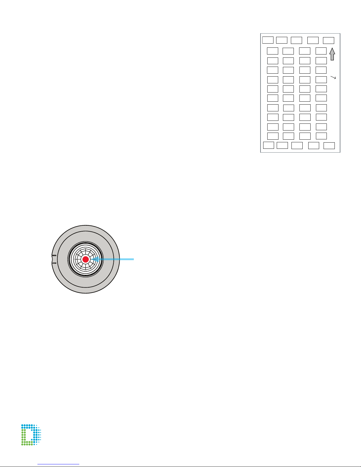
power by locating the DLA heartbeat. Look at the sensor lens: Every 30 seconds, you should see a blinking red LED indicator.
Note that until the DLA unit is programmed using Commissioner software, the DLA unit will use the following settings, which
effectively tell the connected light xture(s) to remain ON at 100%, with no occupancy sensing:
• Active Light Level: 100%
• Inactive Light Level: 100%
• Occupancy Sensor Delay: Sensor Inactive
Heartbeat Indicator
Step Three: Update the Sticker Book
Guidelines
• Each DLA comes with an extra metallic serial number label.
• It is critical that you adhere the label to the sticker book, which represents the facility’s
oor plan. Place the label in the box that corresponds to the relative location of the DLA
within the facility.
• Note that without an accurate and complete sticker book, the facility’s lighting management
software cannot be programmed and the installation process may be delayed.
• The project manager will provide access to the sticker book.
Blank page from a sticker book
created using a CAD program
This manual suits for next models
3
Table of contents
Other Digital Lumens Accessories manuals


