Philio PSM01 User manual

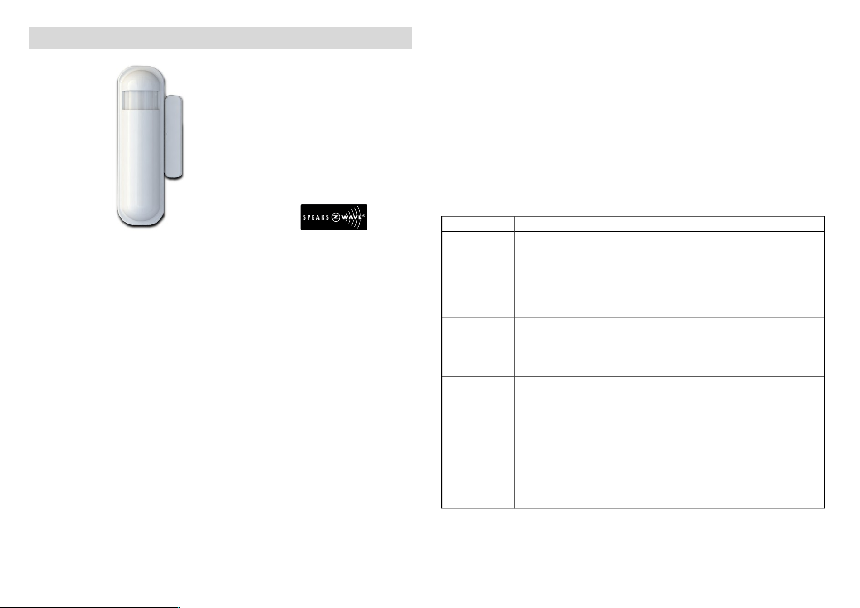
Slim Multi-Sensor PSM01
The slim multi-sensor PSM01 has door/window, temperature and
illumination, 3 sensors function in one, based on Z-Wa eTM technology.
Z-Wa eTM is a wireless communication protocol designed for home
automation, specifically to remotely control applications in residential
and light commercial en ironments. The technology uses a low-power
RF radio embedded or retrofitted into home electronics de ices and
systems, such as lighting, home access control, entertainment systems
and household appliances.
This de ice is one component of the Z-Wa eTM sensor system and is
designed to work with all other Z-Wa eTM enabled de ices in a home
control network. The de ice adopt the Z-Wa eTM 400 series chip, when
your Z-Wa eTM network system is all made by Z-Wa eTM 400 series
de ices. The network system will ha e the ad antages as below.
•Concurrent multi-channel support reduces external interference.
•Better RF range, impro e about 10 meters in indoor.
•Support 100 Kbps transmit speed, speed up communication.
Adding to Z-WaveTM Network
There are two tamper keys in the de ice, one is in the back side,
another is in the front side. They ha e the same function. Both of them
can inclusion, exclusion, reset or association from Z-Wa eTM network.
In the first time, add the de ice into the Z-Wa eTM network. First, make
sure the primary controller is in the inclusion mode. And then power on
the de ice, just take out the insulation Mylar in the back side of the
de ice. The de ice will auto start the NWI (Network Wide Inclusion)
mode. And it should be included in 5 seconds. You will see the LED
light ON one second.
Function Descri tion
Inclusion
1. Ha e Z-Wa eTM Controller entered inclusion mode.
2. Pressing tamper key three times within 1.5 seconds
will enter inclusion mode.
3. After inclusion successful, the de ice will wake to
recei e the setting command from Z-Wa eTM
Controller about 20 seconds.
Exclusion
1. Ha e Z-Wa eTM Controller entered exclusion mode.
2. Pressing tamper key three times within 1.5 seconds
will enter exclusion mode.
Node ID has been excluded.
Reset
1. Pressing tamper key four times within 1.5 seconds
and do not release the tamper key in the 4th
pressed, and the LED will turn ON.
2. After 3 seconds the LED will turn OFF, after that
within 2 seconds, release the tamper key. If
successful, the LED will light ON one second.
Otherwise, the LED will flash once.
3. IDs are excluded and all settings will reset to
factory default.
1

Association
1. Ha e Z-Wa eTM Controller entered association
mode.
2. Pressing tamper key three times within 1.5 seconds
will enter association mode.
Note: The de ice support 2 groups. The group 1 is for
recei ing the report message, like triggered e ent,
temperature, illumination etc. The group 2 is for light
control, the de ice will send the “Basic Set” command
to this group.
•Including a node ID allocated by Z-Wa eTM Controller means
inclusion. Excluding a node ID allocated by Z-Wa eTM
Controller means exclusion.
•Failed or success in including/excluding the node ID can be
iewed from Z-Wa eTM Controller.
Notice 1: Always RESET a Z-Wa eTM de ice before trying to add it to a
Z-Wa eTM network.
Notice 2: When the de ice into NWI mode, any tamper key and
sensor functionality will useless. The NWI will timeout after 30 seconds.
Z-WaveTM Notification
After the de ice adding to the network, it will wake-up once per day in
default. When it wake-up it will broadcast the “Wake Up Notification”
message to the network, and wake-up 10 seconds for recei e the
setting commands.
The wake-up inter al minimum setting is 30 minutes, and maximum
setting is 120 hours. And the inter al step is 30 minutes.
If the user want to wake-up the de ice immediately, please remo e the
front co er, and press the tamper key once. The de ice will wake-up 10
seconds.
Z-WaveTM Message Re ort
* Door/Window Re ort:
When the Door/Window state changed, the de ice will unsolicited to
send the “Sensor Binary Report” to the nodes in the group 1.
Sensor Type: Door/Window (0x0A)
Sensor Value: 0x00 is closed, 0xFF is opened.
* Tam er Re ort:
When the 2 tamper keys in the de ice are pressed o er 5 seconds. The
de ice will into the alarm state. In that state, if any one of the tamper
keys be released, the de ice will unsolicited to send the “Sensor Binary
Report” to the nodes in the group 1.
Sensor Type: Tamper (0x08)
Sensor Value: 0xFF
* Tem erature Re ort:
When the door/window state changed, the de ice will unsolicited to
send the “Sensor Multile el Report” to the nodes in the group 1.
Sensor Type: Temperature (0x01)
Note: To disable this functionality by setting the configuration setting
N0.5, the bit5 of the alue to 1.
*** Temperature differential report ***
This function default is disabled, to enable by setting the configuration
setting NO.6 bit6 to 1.
When the temperature plus or minus three degree Fahrenheit (1.67
degree Celsius), the de ice will report temperature information to the
nodes in the group 1.
The de ice will measure the temperature in e ery 64 seconds. And if
the temperature is o er 140 degree Fahrenheit (60 degree Celsius), the
de ice also report in each measurement.
2

* Illumination Re ort:
When the door/window state changed, the de ice will unsolicited to
send the “Sensor Multile el Report” to the nodes in the group 1.
Sensor Type: Luminance (0x03)
Note: To disable this functionality by setting the configuration setting
N0.5, the bit4 of the alue to 1.
* Timing Re ort:
Beside the e ent triggered could report message, the de ice also
support the timing unsolicited report of the status.
•Battery le el report: E ery 6 hours report once in default.
It could be changed by configuration setting NO. 10.
•Low battery report: When the battery le el is too low, e ery 30
minutes will report once.
•Door/window state report: E ery 6 hours report once in default.
It could be changed by configuration setting NO. 11.
•Illumination le el report: E ery 6 hours report once in default.
It could be changed by configuration setting NO. 12.
•Temperature report: E ery 6 hours report once in default.
It could be changed by configuration setting NO. 13.
Power U Procedure
* Battery Power Check
When the power up, the de ice will detect the power le el of the
battery immediately. If the power le el is too low, the LED will continue
flash about 5 seconds. Please change another new battery.
* NWI
When the power on, the de ice will check is it already adding to the
network? If doesn't, it will auto start the NWI mode. The LED will flash
in e ery second and continue 30 seconds. Until timeout or the de ice
successful to inclusion by controller.
* Wake
When the power on, the de ice will wake about 20 seconds. In this
duration, the controller can communicate with the de ice. Normally the
de ice is always sleeping to sa e the battery energy.
O eration Mode
There are two operation mode, “Test Mode” and “Normal Mode”, the
“Test Mode” is for the user test the sensor function when installation.
When the e ent triggered, normally the LED won't indicated, unless the
battery is in the low le el, the LED will flash once. And in the “Test
Mode” the LED also will light ON one second.
When the e ent triggered, the de ice will report the messages to the
nodes in the group 1. The messages also include the temperature and
the illumination le el. The user can switch the report by configuration
setting NO. 5. When the e ent triggered, if the en ironment luminance
is less than the setting of the configuration setting NO. 4, the de ice
will emit the signal to turn ON the lighting equipment, those nodes in
the group 2. If the e ent is door/window close, it will delay about 5
seconds and emit the signal to turn OFF the lighting equipment.
Notice: When the tamper key of the back side is in the released state,
the de ice always in the “Test Mode”.
3

Battery Installation
When the de ice report the low battery message. The user should
replace the battery to new one.
The way to open the front co er please follow below steps.
1. Using a tool like (1) to press 1-1 till hear a click sound
2. Hold the front co er and pull back
3. Hold the front co er and pull up
Replace the new battery and install the co er back.
1. Put the front co er bottom to 1-1, and press down.
2. Push the front co er top to 2-1.
Choosing a Suitable Location
1. Don't let the de ice facing the window or the sunlight.
4

Installation
1. In the first time, add the de ice into the Z-Wa eTM network. First,
make sure the primary controller is in the inclusion mode. And then
power on the de ice, just take out the insulation Mylar in the back side
of the de ice. The de ice will auto start the NWI (Network Wide
Inclusion) mode. And it should be included in 5 seconds. You will see
the LED light ON one second.
2. Let Controller associate with Group 1 of the de ice, any light switch
that intend to be turned on when the de ice trig please associate to
Group 2 of the de ice.
3. In the accessory pack. There are two type of double coated tape,
one is thicker (hereinafter referred to as A tape) and another is thinner
(hereinafter referred to as B tape), you can use A tape for the test at
the beginning. The right way for A tape installation is stick it to the
position below tamper key. The thicker tape won't let the tamper key
close, so the sensor will enter the test mode, You may test if installed
position is good or not by this way.
After finish the test and decide to fix, then you can remo e tape A, and
mounting the sensor by using tape B. This will close the tamper key
and let the sensor enter normal mode.
Z-Wave Configuration Settings
Notice: The data size of the configuration settings is 1.
NO. Name Default Valid
Values Description
2 Basic Set Le el 255 1~100,
0xFF
Setting the BASIC command alue to
turn on the light. The 0xFF(-1) means
5

turn on the light. For dimmer equipment
1 to 100 means the light strength.
4Light
Threshold 99 0~100
Setting the illumination threshold to turn
on the light. When the e ent triggered
and the en ironment illumination lower
then the threshold, the de ice will turn
on the light.
0 means turn off illumination detected
function. And ne er turn on the light.
1 means darkest.
99 means brightest.
100 means turn off illumination detected
function. And always turn on the light.
Notice: In none test mode, only the
alue in 1 to 99 will enable the
illumination detected function and
update the illumination alue.
5Operation
Mode 00~127
Bit0: Re ersed.
Bit1: Re ersed.
Bit2: Disable the door/window function.
Bit3: Setting the temperature scale.
0: Fahrenheit, 1:Celsius
Bit4: Disable illumination report after
e ent triggered.
Bit5: Disable temperature report after
e ent triggered.
6 Multi-Sensor
Function
Switch
40~127 Multi-Sensor function switch. Using bit to
control.
Bit0: Disable magnetic integrate
illumination.
Bit1: Reser ed, always 1.
Bit2: Reser ed, always 1.
Bit3: Reser ed.
Bit4: Disable delay 5 seconds to turn off
the light, when door/window closed.
Bit5: Disable auto turn off the light, after
door/window opened to turn on the
light.
Bit6:Enable temperature monitoring.
When this bit enable, the temperature
changed 3 degree Fahrenheit, it will
report.
And also the temperature o er 140
degree Fahrenheit, it will report e ery 64
seconds.
9Turn Off Light
Time 44~127
After turn on the light, setting the delay
time to turn off the light. 8 seconds per
tick, and minimum time is 32 seconds,
default tick is 4 (32 seconds).
10 Auto Report
Battery Time 12 1~127
The inter al time for auto report the
battery le el. 30 minutes per tick and
minimum time is 30 minutes, default tick
is 12 (6 hours).
11
Auto Report
Door/Window
State Time
12 1~127
The inter al time for auto report the
door/window state. 30 minutes per tick
and minimum time is 30 minutes, default
tick is 12 (6 hours).
12
Auto Report
Illumination
Time
12 1~127
The inter al time for auto report the
illumination. 30 minutes per tick and
minimum time is 30 minutes, default tick
is 12 (6 hours).
13
Auto Report
Temperature
Time
12 1~127
The inter al time for auto report the
temperature. 30 minutes per tick and
minimum time is 30 minutes, default tick
is 12 (6 hours).
6

Z-Wave Su orted Command Class
COMMAND_CLASS_CONFIGURATION
COMMAND_CLASS_VERSION
COMMAND_CLASS_SENSOR_BINARY_V2
COMMAND_CLASS_ASSOCIATION_V2
COMMAND_CLASS_MANUFACTURER_SPECIFIC_V2
COMMAND_CLASS_WAKE_UP_V2
COMMAND_CLASS_SENSOR_MULTILEVEL_V5
COMMAND_CLASS_BATTERY
COMMAND_CLASS_BASIC
S ecifications
Power by CR123A lithium battery.
Signal (Frequency):
868.42 MHz(EU),
908.42 MHz(US),
922~926 MHz(JP/TW)
Range:
Minimum 30 meters indoor,
70 meters outdoor line of sight.
Operating Temperature: -10oC ~ 40oC
For indoor use only.
Specifications subject to change without notice due to continuing
product impro ement.
FCC Interference Statement
This equipment has been tested and found to comply with the limits for
a Class B digital de ice, pursuant to Part 15 of the FCC Rules. These
limits are designed to pro ide reasonable protection against harmful
interference in a residential installation. This equipment generates, uses
and can radiate radio frequency energy and, if not installed and used in
accordance with the instructions, may cause harmful interference to
radio communications. Howe er, there is no guarantee that
interference will not occur in a particular installation. If this equipment
does cause harmful interference to radio or tele ision reception, which
can be determined by turning the equipment off and on, the user is
encouraged to try to correct the interference by one of the following
measures:
•Reorient or relocate the recei ing antenna.
•Increase the separation between the equipment and recei er.
•Connect the equipment into an outlet on a circuit different from
that to which the recei er is connected.
•Consult the dealer or an experienced radio/TV technician for
help.
This de ice complies with Part 15 of the FCC Rules. Operation is subject
to the following two conditions:
(1) This de ice may not cause harmful interference, and
(2) This de ice must accept any interference recei ed, including
interference that may cause undesired operation.
FCC Caution: Any changes or modifications not expressly appro ed by
the party responsible for compliance could oid the user's authority to
operate this equipment.
This transmitter must not be co-located or operating in conjunction
with any other antenna or transmitter.
7

Warning
Do not dispose of electrical appliances as unsorted municipal waste,
use separate collection facilities. Contact your local go ernment for
information regarding the collection systems a ailable. If electrical
appliances are disposed of in landfills or dumps, hazardous substances
can leak into the groundwater and get into the food chain, damaging
your health and well-being.
When replacing old appliances with new once, the retailer is legally
obligated to take back your old appliance for disposal at least for free
of charge.
8
Table of contents
Other Philio Accessories manuals

Philio
Philio TSM01 User manual

Philio
Philio PAN11-5 User manual

Philio
Philio PAT02-A User manual

Philio
Philio DCH-Z110 User manual

Philio
Philio PSP01 User manual

Philio
Philio PAT02-B User manual

Philio
Philio PAN11 User manual

Philio
Philio PAD02 User manual

Philio
Philio PSP05 User manual

Philio
Philio PHI PST02-1B User manual

Philio
Philio PAT12 User manual

Philio
Philio PAT12-A User manual

Philio
Philio Z-Wave PHI PSM02 User manual

Philio
Philio PHI PST02-1C User manual

Philio
Philio PHI PST02-1B User manual

Philio
Philio PST07 User manual

Philio
Philio PST07 User manual

Philio
Philio PAD02 User manual

Philio
Philio PSM02 User manual

Philio
Philio PAN15-2 User manual