Digital Millwork Little Baron Fokker DR I Instructions for use
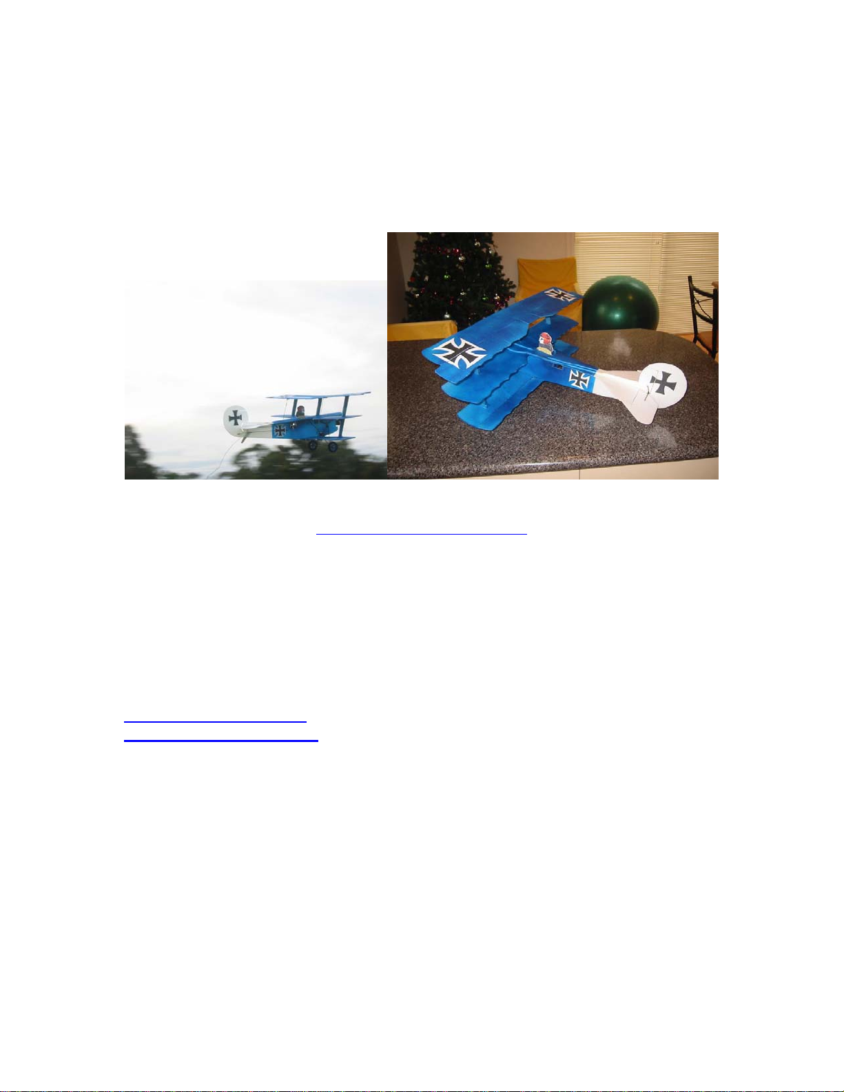
Little Baron
Indoor Fokker Dr I Tri-plane
Construction Manual
Designed by Peter Stapleton
‘pmjass’ on rcgroups.com
Little Baron RC Groups Thread
Wingspan: 27 in Length: 23 in
Wing Area: 276 sq in Flying weight: 6 to 8oz
Kit #DMRC0001D by:
Digital Millwork
8038 E. Brown Rd
Lowell, AR 72745
www.digitalmillwork.com
© 2005 Digital Millwork

Digital Millwork Deluxe kits are very complete requiring only your radio, battery, and
chosen propulsion system.
Items included in kit:
CNC Cut white Depron Foam, balsa and ply parts
Carbon Fiber pushrods
Control horns
Carbon fiber rods for undercarriage construction
Wheels
Velcro for battery/radio mounting
Instruction manual on CD-Rom
Printable graphic files of insignia and pilot
Items needed to complete deluxe kit:
4 Channel Receiver and 3
Servos: Servo cutouts are sized for GWS Pico servos, usa a
small 4 channel receiver such as GWS pico, Berg
microstamp etc.
Recommended motors and
ESC:
Mounts are included for IPS mount, spindle
mount, front collar or rear flange mount.
Brushless motor recommended for 3D
performance.
Brushed: GWS IPS ‘S1’ (IPS-DX2BB-1XCS)
GWS ICS 100 Electronic Speed
Control or similar
Prop: GWS 8060 SF
Brushless: CD rom size brushless motor such as
Len’s RC 17 or 25 turn or AXI 2204
series
Castle Creations Phoenix 10 ESC or
similar
Prop: GWS 8040 DD
Battery: Small 7.4V Lithium Poly battery in 700mah to 1320
mah range
Glue: Odorless Medium CA and foam safe accelerator plus
Contact Cement, Hot melt glue, or Gorilla glue
Tape: Control services can be hinged with clear packing
tape, Medex tape or with hinges of your preference.
Other common building supplies including: 1/8” drill bit, straight edge, scissors, sand
paper, hobby knife, small square, pins etc.
2

Note: This is Little Baron manual version 1.0. Before beginning
construction, you should check for an updated manual on the Digital
Millwork website: http://www.digitalmillwork.com .
Manual Revision History:
3/15/05 ver 0.9 to version 1.0
oAdded brushed motor information to specs
oChanged recommended starting C.G. to 1 1/8th inch back on middle wing
oAdded note to apply packing tape to aileron surfaces to reduce flex for
outdoor flight.
3
Indoor Fokker DR I Construction:
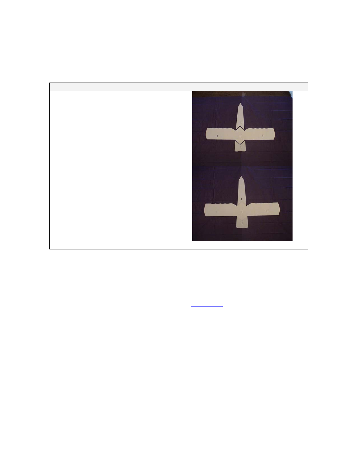
Step 1: Upper Fuselage
Wing and Fuse assembly
oOn a flat surface, glue middle wing to
fuselage front and fuselage rear.
Note: Painting your Fokker
This manual does not detail the painting of your aircraft as everyone has their own preferences. You may
want to paint the parts before or during assembly or you may want to wait till it’s complete. Be sure to test
your paint on a scrap piece of foam to make sure it’s foam safe. Many of the spray type paints will eat
foam if sprayed from too close of distance. You may want to consider using a water based acrylic craft
paint or even Sharpie markers. There are many threads on rcgroups.comon foam finishing techniques. As
this is a lightweight indoor model, be sure not to add to much weight when finishing your aircraft.
4
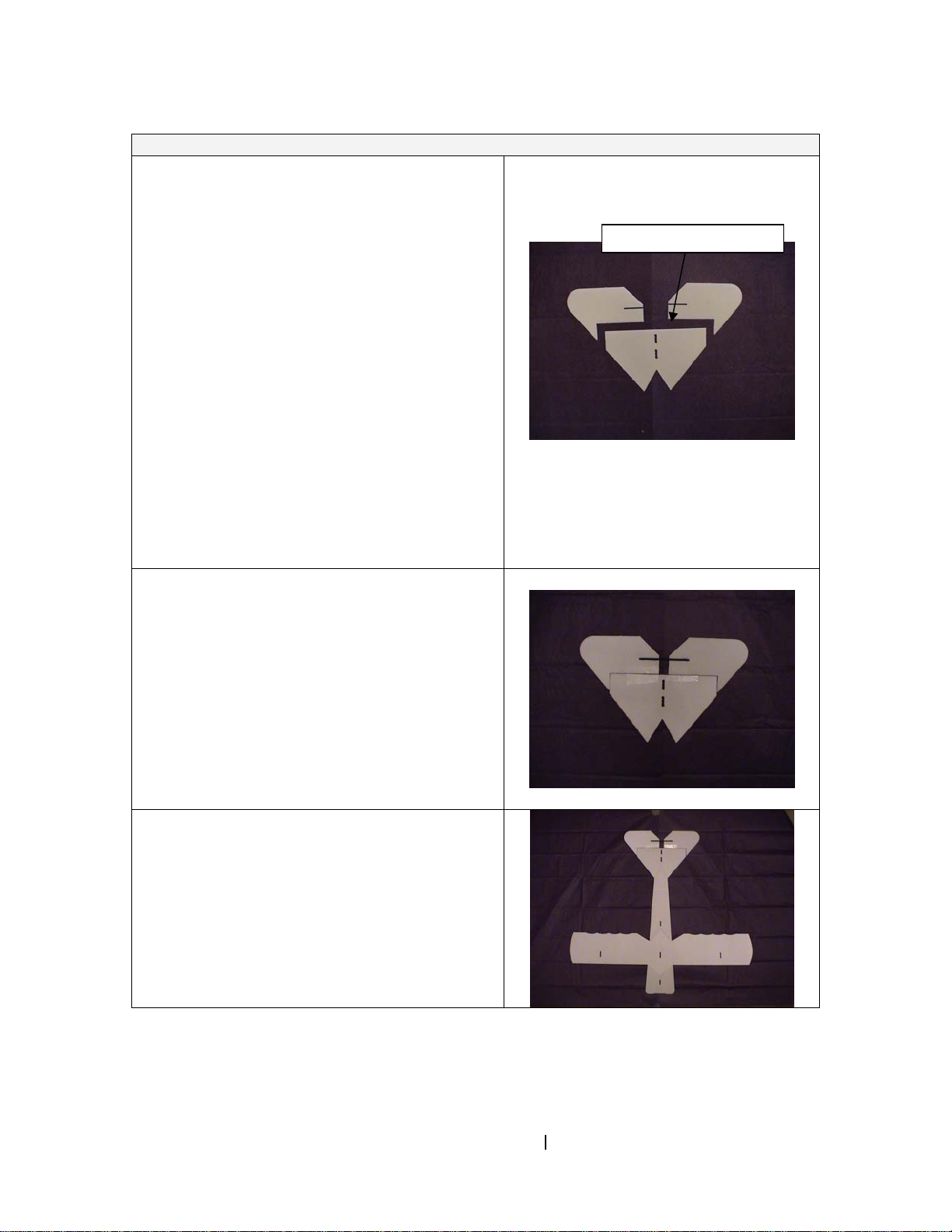
Hinge Elevators to stabilizer
oHinge the two elevator pieces to the
stabilizer. The elevator control horn slot
should be on the left elevator when looking
from the top rear of the elevator assembly.
To use tape hinges, sand a 45 degree angle on the
bottom side of the front of the two elevator pieces. With
the stabilizer on the edge of your work table, hold the
elevator piece at it’s maximum downward angle of 45
degrees and tape to stabilizer. Repeat for other elevator
half. Flip the assembly upside down and hold each
elevator piece downward at it’s maximum throw of 45
degrees and tape following the contour of the sanded
area. Repeat for other side. For better tape adherence,
you may want to coat the foam surface where the tape
will be with a thin layer of contact cement. Going over
the applied tape with a covering iron on a low setting
also seems to improve adherence.
oGlue the supplied 2 3/4“ 1.5 mm carbon tie
rod between the elevator pieces making
sure both the elevators are flat on a solid
surface.
oGlue completed elevator/stabilizer to wing
and upper fuselage assembly from Step 1.
Control horn slot on left side
5
Popular Toy manuals by other brands

FUTABA
FUTABA GY470 instruction manual

LEGO
LEGO 41116 manual

Fisher-Price
Fisher-Price ColorMe Flowerz Bouquet Maker P9692 instruction sheet

Little Tikes
Little Tikes LITTLE HANDIWORKER 0920 Assembly instructions

Eduard
Eduard EF-2000 Two-seater exterior Assembly instructions

USA Trains
USA Trains EXTENDED VISION CABOOSE instructions


