Digital Systems Design GBS-8219 User manual
RGB ELEKTRONIKA AGACIAK CIACIEK
SPÓŁKA JAWNA
Jana Dlugosza 2-6 Street
51-162 Wrocław
Poland
biuro@rgbelektronika.pl
+48 71 325 15 05
www.rgbautomatyka.pl
www.rgbelektronika.pl
DATASHEET
www.rgbautomatyka.pl
www.rgbelektronika.pl
OTHER SYMBOLS:
GBS-8219
GBS8219, GBS 8219, GBS-8219
INDUSTRIAL MONITOR CONVERTER
YOUR
PARTNER IN
MAINTENANCE
At our premises in Wrocław, we have a fully equipped servicing facility. Here we perform all the repair
works and test each later sold unit. Our trained employees, equipped with a wide variety of tools and
having several testing stands at their disposal, are a guarantee of the highest quality service.
OUR SERVICES
ENCODERS
SERVO
DRIVERS
LINEAR
ENCODERS
SERVO AMPLIFIERS
CNC
MACHINES
MOTORS
POWER
SUPPLIERS
OPERATOR
PANELS
CNC
CONTROLS
INDUSTRIAL
COMPUTERS
PLC
SYSTEMS
Repair this product with RGB ELEKTRONIKA ORDER A DIAGNOSIS ∠
Buy this product at RGB AUTOMATYKA BUY ∠

User Manual 1
Digital Systems Design
May 2011
-- Converted from Word to PDF for free by Fast PDF -- www.fastpdf.com --

User Manual 2
Copyright
Notice
and
Disclaimer
All rights reserved. No parts of this manual may be reproduced in any form without the
express written permission of Digital Systems Design. Digital Systems Design makes
no representations or warranties with respect to the contents hereof. In addition,
information contained herein is subject to change without notice. Every precaution has
been taken in the preparation of this manual, nevertheless, Digital Systems Design
assumes no responsibility for errors or omissions or any damages resulting from the
use of the information contained in this publication.
All other trademarks belong to their respective owners.
Before using this product for the first time, please read the User Manual carefully as it
contains all product-related warnings and important guidance for use.
Do not carry out any of the following:
• Unauthorized repairs or parts replacement.
• Non-standard usage.
Inappropriate exposure, including but not limited to lightning, fire, exposure to rain,
water, gas.
Use of any form of power supply, outside the allowable voltage operating range.
• Removal or modification of the manufacturers warranty label.
!
!!
!
WARNING
WIZARD GAME
DO NOT
UNCOVER
To avoid electric shock, do not
remove the metal case, carry out
unauthorized repairs or parts
replacement. Other non-standard
operations are prohibited. Please
return to factory for repair.
-- Converted from Word to PDF for free by Fast PDF -- www.fastpdf.com --

User Manual 3
2. Features
The manufacturer is an industry leader in long-term maintenance and reconstruction of
industrial monitors & display systems, especially those used in conjunction with CNC
machinery. After many years of development and testing, and on the strength of previous
products in the industrial CNC video field, the GBS-8219 was developed. The GBS 8219
accepts a wide range of Industrial video signals, RGB/CGA/VGA and allows them to be
converted for use on modern VGA/SVGA display systems, such as LCD panels, which are
far more widely available, and much cheaper and safer to use. The latest video conversion
technology allows fully automated operation, without the need for additional device
programming using PC interfaces – the 8219 is a fully standalone conversion system.
- Feature specifications
Signals MDA
CGA
EGA
RGB
RGB Sog
RGBS
RGBHV
YPbPr
Interface 9pin
3pin
6pin
14pin
20pin
25pin
Input
Horizontal
Frequency
Rate(H)
12kHz to 40kHz
Automatically recognized
Supports 15pin VGA
Resolution:800*600/60HZ
or custom-resolution
Output Interface D-Sub 15 PIN standard VGA port
Power DC 12V 1.0A
Note:
1. YPbPr = YUV
2. Input Horizontal Frequency Rate 12kHz to 40kHz automatically recognized.
3. Supports RGB and YPbPr
4. Supports Interlaced Scanning and Line by Line Scanning.
5. Supports Vertical Resolution from line200 to line 600 automatically recognized.
6. Supports variable Horizontal Resolution automatically recognized
7. Supports RGBHV (separate sync) ,RGBS (composite sync), automatically recognized
8. Output resolution: 800*600/60Hz standard VGA or custom-resolution.
-- Converted from Word to PDF for free by Fast PDF -- www.fastpdf.com --
User Manual 4
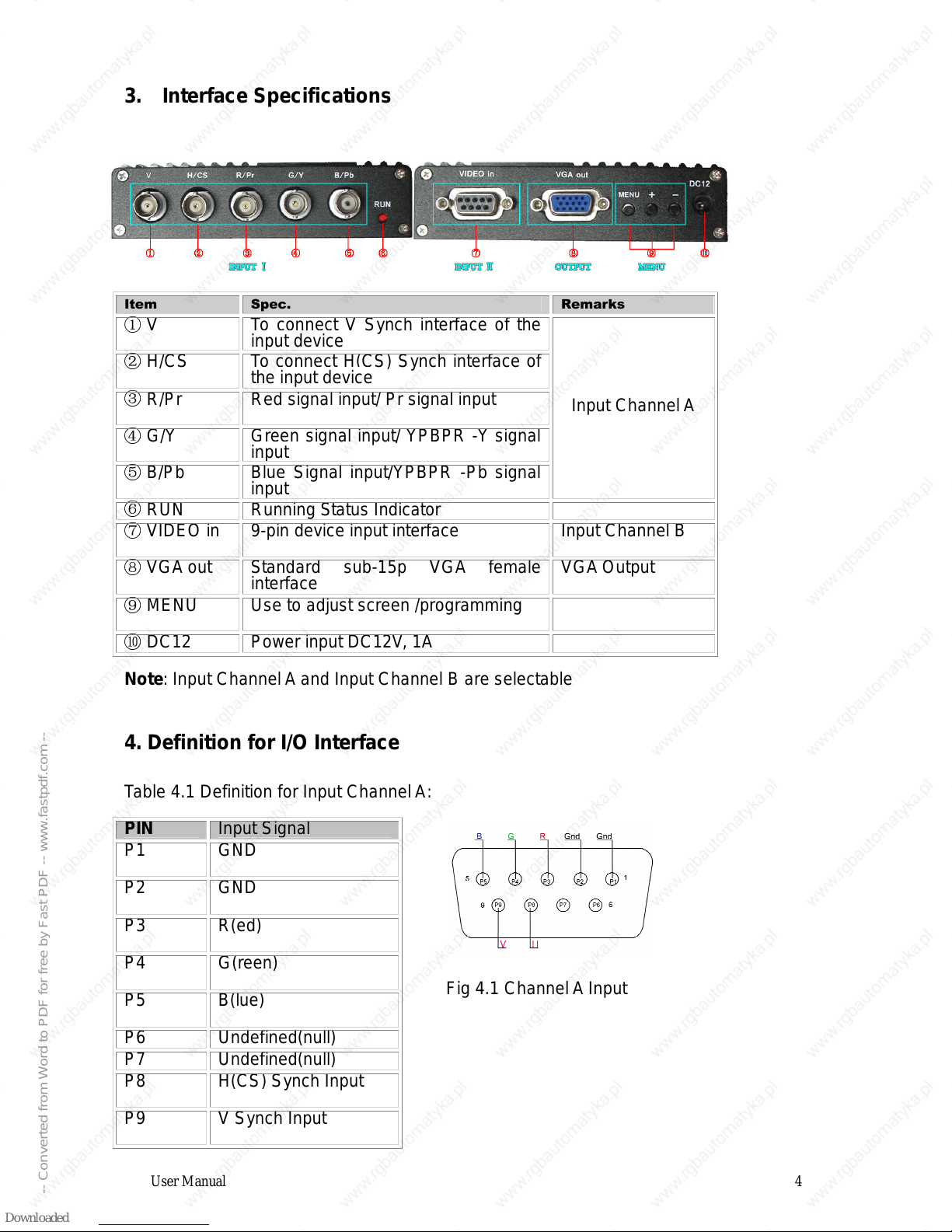
3. Interface Specifications
" # $
V To connect V Synch interface of the
input device
H/CS To connect H(CS) Synch interface of
the input device
R/Pr Red signal input/ Pr signal input
G/Y Green signal input/ YPBPR -Y signal
input
B/Pb Blue Signal input/YPBPR -Pb signal
input
Input Channel A
RUN Running Status Indicator
VIDEO in 9-pin device input interface Input Channel B
VGA out Standard sub-15p VGA female
interface VGA Output
MENU Use to adjust screen /programming
DC12 Power input DC12V, 1A
Note: Input Channel A and Input Channel B are selectable
4. Definition for I/O Interface
Table 4.1 Definition for Input ChannelA:
Fig 4.1 Channel A Input
PIN Input Signal
P1 GND
P2 GND
P3 R(ed)
P4 G(reen)
P5 B(lue)
P6 Undefined(null)
P7 Undefined(null)
P8 H(CS) Synch Input
P9 V Synch Input
-- Converted from Word to PDF for free by Fast PDF -- www.fastpdf.com --

User Manual 5
Table 4.2 Definition for Input Channel B
% ! " !
PbYPr YPbPr input signal (Fig
4.2)
Interface: three BNC slot,
connected to the
corresponding Pb, Y, Pr
interface, then Y
monochrome port.
Fig 4.2Analog 3BNC (YPBPR) Input.
RGB RGB SOG input signal
(Fig 4.3)
Interface: three BNC slot,
connected to the
corresponding R, G, B
slot, then G monochrome
port.
Figure 4.3 Analog 3BNC (RGB SOG)
Input.
RGBS RGBS CS Composite
Sync (Fig 4.4)
Interfaces: 4 BNC slot,
connected to the
corresponding R, G, B, S
I, monochrome then G, S I
Figure 4.4 Analog 4BNC (RGBS CS)
Input.
RGBHV RGBHV separate sync
(Fig 4.5)
Interface: 5 BNC port,
connected to the
corresponding R, G, B, H,
V I, monochrome then G,
H, V I
Figure 4.5 Analog 5BNC (RGBHV)
Input.
-- Converted from Word to PDF for free by Fast PDF -- www.fastpdf.com --

User Manual 6
5. Operational OSD Menu
6. Kit Accessories Contents
Table 6.1Accessories list
&'( # $
User Manual 1 English
Power Adaptor 1 DC12V,1A
Half 9pin cable 1
9 pin M-F cable 2 1 Male + 1 Female
Table 6.2 9-Pin cable pinout
Figure 6.2 Half 9pin cable
%
" !
A Silver Shield
B Black Ground(GND)
C White Vertical Synch(V)
D Orange Horizontal Synch(H)
E Blue Blue(B)
F Green Green(G)
G Red Red(R)
H Brown Undefined(null)
)"
MENU -Press to enter the OSD
menu
-Press once to select
andthen press again to
exit the current line
“+” -Press it to move the
cursor up
-Press to increment the
value
“-“ -Press to move the cursor
down
-Press it to decrement the
value
-- Converted from Word to PDF for free by Fast PDF -- www.fastpdf.com --

User Manual 7
7. Assembly and Configuration
• Connect all cables and connect the system power supply via the 12VDC jack
connector.
• Power up the host system and ensure the video signals and plugs are correctly
connected. If either the picture display or display colors are not correct, adjust the
video source variables using the OSD menu adjustments. Change the OSD menu
settings to those of the input video signal. (Available options are: YUV color, RGB (D)
digital TTL signals, RGB (A) mode may signal).
• The system processor can automatically detect and identify the input signal. If you
carry out the initial signal adjustment highlighted above, there should be no need to
manually adjust the additional settings; if there is any image distortion to the output
video picture, you may need to manually adjust the synchronization signal, and the
signal source settings to get a high quality output video image.
•
If the screen shows elongated or stretched images, or the picture is not correctly
situated in the centre of the screen (eg: the bottom part of the converted image is
missing off the bottom of the display), then try to adjust the scanning mode to
Progressive Scan (Progressive); if the adjustment of the vertical position is at the
maximum level, and the output image display is still only half of the display total size,
then change the scanning mode to interlaced scan (Interlaced).
•
Adjust the horizontal position, horizontal size, vertical position, and vertical size of
the display.
•
Select the correct input source impedance; the display should have a normal clear
and sharp image picture. If the signal is saturated, please adjust the setting.
•
If the image appears with small vertical waves or with a jitter effect, try to adjust the
value or the input signal phase to correct the output image.
•
Save all the parameters and exit the menu using the ‘Save and Exit’ Option
For any other setup problems or support issues, contact:
support@digitalsystemsdesign.co.uk
Or visit out website at:
www.digitalsystemsdesign.co.uk
-- Converted from Word to PDF for free by Fast PDF -- www.fastpdf.com --
Table of contents
Other Digital Systems Design Media Converter manuals

Popular Media Converter manuals by other brands


DataKinetics
DataKinetics DSC110 user manual

StarTech.com
StarTech.com VID2HDMITV Features

Transition Networks
Transition Networks CBFTF1011-100 user guide

TR-Electronic
TR-Electronic Profibus 582 Series Assembly instructions

Transition Networks
Transition Networks F-SM-MM-05 user guide

ARC
ARC BLE-1915 manual


