digitalview M3-320 User manual

M3-320
USER GUIDE
Version 1.1

2
Revision History
Amendment Date
Version
March 2009
V1.0
September, 2010
V1.1
Page

3
Table of Contents
................................................................................1 Introduction 4
.............................................................................2 System Design 6
..................................................................................3 Quick Start 8
.................................................................................................................3.1 Prepare for connection 8
.......................................................................................................3.2 Basic connection for M3-320 9
............................................................................4 General Notes 10
.....................................................5 Connectors, pinouts & jumpers 13
............................................................................6 System Setup 22
...........................................................................................................................6.1 Select switches 22
....................................................................................................................6.2 OSD Configuration 22
.......................................................................................................................................6.3 Start up 23
..............................................................................................................6.3.1 Start track mode 23
......................................................................................................................6.3.2 Sleep mode 23
............................................................................................................................6.4 Loop Playback 24
.................................................................7 Operating Instructions 25
........................................................................................................................7.1 Operating modes 25
...................................................................................................................7.1.1 Playlist mode 25
............................................................................................................7.1.2 Simple play mode 25
....................................................................................................................7.2 Operating functions 26
................................................................................................................................7.3 USB Update 27
....................................................................................................................7.4 Formatting SD card 29
....................................................................................................7.5 Exporting Project and Playlist 30
............................................................................................................................7.6 Network setup 31
.................................................................................8 Dimension 33
..............................................................................9 Specification 34
Page

4
1Introduction
This brief guide explains how to use and set up your M3-320 decoder board. It is
intended for Digital View staff who assemble ViewStream product for demos or
for customers, and for resellers.
The M3-320 is an MPEG decoder board designed to use with Video Monitors for
playing MPEG-2/MPEG-4 video and audio files.
MPEG-2, MPEG-4* video
JPEG picture
MP3 audio file
Video signals of PAL & NTSC standard
Composite signal output
DVI output
Audio output
RS-232 port
USB Update
LAN (RJ-45) port
* DivX MPEG-4 format
IMPORTANT USAGE NOTE
☞!All media filenames must be in 16.3 format (e.g. xxxxxxxx.xxx) though
combinations with 7.3, 10.3 etc are fine.
Where: “16” is the maximum of alpha-numeric character to be used.
“3” is the file extension like .mpg / .jpg / .avi etc.
☞!Do not use any “Non alpha-numeric” characters like ‘~’, ‘_’, ‘-‘, ‘&’, ‘^’,
etc.
NOTE: If ‘Non alpha-numeric character’ or the ‘8.3’ format are not followed, the
player will not recognize the playlist.
This equipment is for use by developers and integrators; the manufacturer
accepts no liability for damage or injury caused by the use of this product. It is
the responsibility of the developer, integrators or other users of this product to:
Ensure that all necessary and appropriate safety measures are taken.
Obtain suitable regulatory approvals as may be required.
Check power settings to all component parts before connection.
DISCLAIMER
There is no implied or expressed warranty regarding this material.
Page

5
Page

6
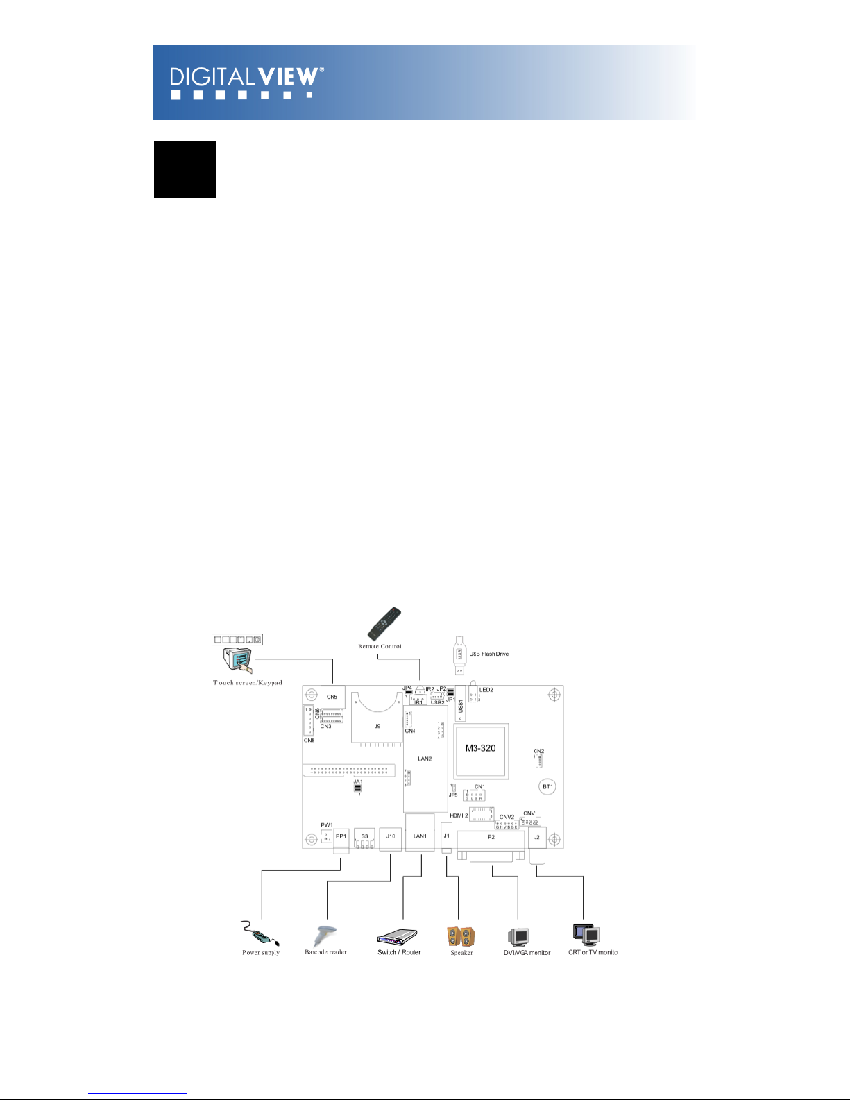
2 System Design
M3-320 Connector Summary:
Summary:
1. Switches and buttons connector (1
– 8 button)
13. Power input (DC 12V)
1. Reserved
14. COM port
1. Remote Ext. (1-8 button)
15. Alternative Composite out and
audio out
1. Switches and button connector (9
– 16 button)
16. Audio out (Line out)
1. SD card slot
17. DVI / VGA out
1. Power / Status LEDs
18. Composite out
1. USB connector
19. LAN port (RJ-45)
1. IR connector
20. Reserved
1. Power on/off switch connector
21. DIP switch (4-pos)
1. Speaker out connector
22. Alternative LAN (WiFi)
1. Alternative DVI out
1. Alternative VGA out
Page

7
A) Mechanical buttons
•Standard MV-switchmount (P/N:416101300-3) for 1-8 buttons when
connected to the button connector CN6 via the standard switchmount
cable (P/N:426451100-3) or connected to the Remote Ext. socket
(CN5) via the standard cable (P/N:426631800-3).
•Custom made switchmount for 1-16 buttons when connected to the
buttons connector CN6 and CN3 via the standard switchmount cable (P/
N:426451100-3)
•Custom made switchmount for 1-8 buttons when connected to the
Remote Ext. socket (CN5) for alternative remote control buttons via the
standard cable (P/N:426631800-3).
B) Touch screen segments
•The M3-320 when connected with a LCD interface controller can output
videos on to LCD screen. Button control can be performed via touch
screen for panel sizes of 7”, 8”, 10”, 15” and 21.5”
•There is one type of button pattern layouts on the touch screen
available: 8 buttons
(For any special button layout, please contact local sales office.)
Fig. 1 8-buttons for LCD touch screen
C) Button function settings
•Whether the buttons are of the mechanical type (on the standard
switchmount or custom made) or the touch screen segment type, each
button function can be programmed with the DV Studio Software
program to perform a VCD player mode function or specific track select
function. (See DV Studio Software user manual).
•The DV Studio Software program is separately provided
Page
8
3 Quick Start
CAUTION: Never connect or disconnect parts of the system when the system is
powered up as this may cause serious damage.
3.1 Prepare for connection
Connection and usage are straightforward. However, care needs to be taken
with the following:
•Ensuring parts have been correctly connected – both power & signal
considerations.
•Checking that all switches and jumpers are set correctly.
•The input signal is compatible.
•Legal & safety requirements have been met.
•If you are using supplied cables & accessories, ensure they are correct
for the model of video monitor.
•If you are making your own cables & connectors refer carefully to the
video monitor specifications and the “Connectors, Pin outs & Jumpers”
section in this user guide to ensure the correct pin-to-pin wiring.
Page

9
3.2 Basic connection for M3-320
•Connect the keys pad to CN5 (if required)
•Set the DIP switch#1 (S3) to the chosen output connector.
•If Composite video output is selected, set the DIP switch#2 (S3) for
“PAL” or “NTSC” selection.
•Connect the video and audio ext. cables from the M3-320 to the
monitor.
•Connect the power supply (DC 12V @ 1.2A minimum. - ensure correct
+ & - orientation) to the controller power input (PP1).
•Connect the on/off switch cable (p/n:426680401-3) or short Pin1-2 at
PW1 for “Auto power on”
For a detailed system setup, go to section 6
Page

10
4 General Notes
The M3-320 is designed for use with Video Monitors and other analogue
signal input displays. Here are some notes for correct use:
•Preparation - Before you proceed, please familiarize yourself with the
various connectors, jacks, switches and function buttons of the M3-320
unit (see the ‘System Design’ diagram).
•The unit - Handle the unit with care; any knocking may cause
components to come loose and disconnect. Operate in a cool and dry
place.
•Power Input: 12V DC, 1.2A (minimum) is required; this should be a
regulated supply. Power connector is using DC jack, 2.5mm diameter
(Center +)
•Video output – Video - displays PAL & NTSC signals with composite
out. The PAL/NTSC switch should be set correctly.
•Audio output – Audio - Stereo output. Master volume is controlled
through OSD with switch mount buttons.
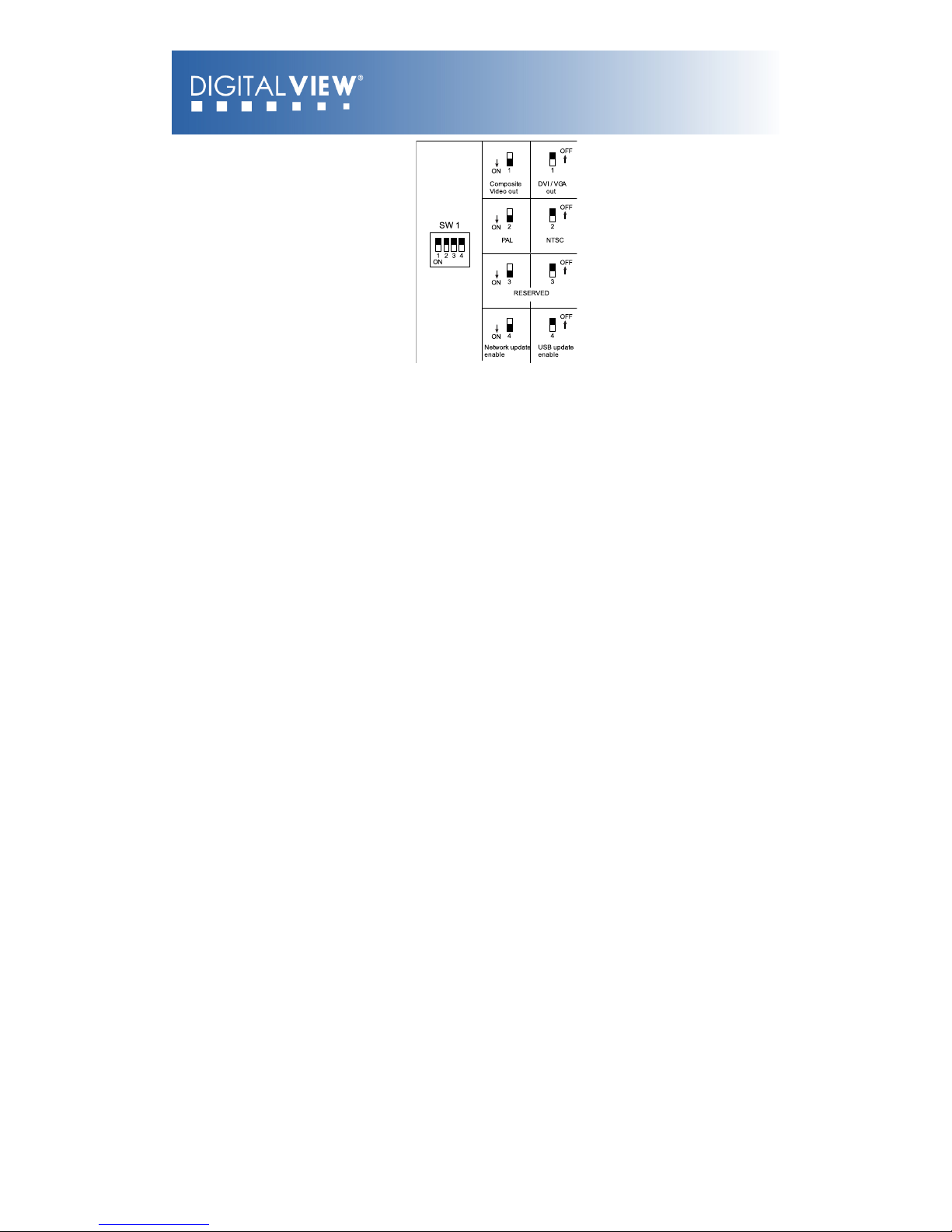
•DIP Switch settings (S3) – To define and select the source of output
and USB/LAN.
oSW1-1 (Output selection):
DVI/VGA: If it is selected, the output resolution is set to
1280x720p60Hz*
Composite: If it is selected, the video format (PAL/
NTSC) is determined by SW1-2.
oSW1-2 (PAL/NTSC selection): When using Composite output
connectors this should be set according to the input
requirements of the video display being used.
oSW1-4 (Content update selection): You may only choose either
one way (LAN or USB) to update content without removing SD
card.
Page
11
*An optional DVI to VGA adapter is required
•Remote Ext. - Using the standard switch mount (p/n: 416101300-3) -
8 momentary buttons for OSD config and video playback control
(standard functions (in simple play mode) being: Play, Stop, Pause,
Next Track, Volume decrease, Volume increase, Mute). An optional
function control device is a custom-made switch mount connected to
the switches and buttons connectors (CN6 and CN3) with a maximum of
16 momentary buttons
•Remote Ext. cable - The cables (p/n: 426631800-3) to the switches
and buttons connector should be of suitable quality and length so that
impedance does not affect performance. Generally lengths up to 1
meter (3 feet) should be acceptable.
•LED (LED2) - The power LED indicator shows power is being supplied
to the M3-320. The Status LED indicates the status of SD card.
•RS-232 port – Requires RJ-11 to DB-9 extend cable (p/n:
426894301-3) for RS-232 connection. This serial port supports barcode
scanner and RS-232 command control. The baud rate must be set to
(9600, n,8,1) and record suffix is set to CR (0DH).
•USB – USB Host. Use USB memory stick for content update without
removing the SD card. The M3-320 will reset power when the USB stick
is detected inserting into the USB connector or removing from the USB
connector. (For the details of USB content update, please refer to the
Application note.)
•DVI out – Supports DVI or VGA. Both DVI and VGA signal are sharing
the same connector. A DVI to VGA adapter is required if connect to
VGA.
Note: This DVI/VGA out is currently set to 1280x720 resolution which may not
be supported by all monitors. If the display looks reasonable but not perfect
please use the OSD settings of the monitor to adjust image position and tuning.
(sometimes called Phase, H. size, H. Freq, etc) It may also be necessary to
adjust image size.
Page

12
•Infra-red (IR) - Supports IR control with DV remote control handset
(P/N:559000104-3). The IR sensor and cable kit (P/N:446010401-3)
are required. The IR control functions are shown as below.
•Service & Warranty: Warranty is invalidated if the unit is dismantled
in any way. The unit is not user serviceable or repairable.
CAUTION: Do not attempt to remove any part of the casing or internal
parts.
Page

13
5 Connectors, pinouts &
jumpers
The various connectors are:
Ref
Purpose
Description
CN1
Speaker out (L/R) connector
JST B4B-XH-A
CN2
Reserved
Hirose 1.25mm, 4-pin,
DF13-4P-1.25DSA
CN3
Switches and buttons connector
(#9 - #16)
Hirose 1.25mm, 9-pin,
DF13-9P-1.25DSA
CN4
Reserved
Hirose 1.25mm, 6-pin,
DF13-6P-1.25DSA
CN5
Remote Ext. (#1 - #8)
MINI DIN 8-way
CN6
Switches and buttons connector
(#1 - #8)
Hirose 1.25mm, 9-pin,
DF13-9P-1.25DSA
CN8
Reserved
JST B6B-XH-A
CNV1
Alternative Composite and Audio
output
JST B5B-PH-K
CNV2
Alternative VGA output
JST B6B-PH-K
HDMI 2
Alternative DVI output
JST BM20B-SRDS
LED2
Power (up)/Status (dn) LEDs
Stacked housing LED
J1
Audio out (Line out)
Stereo Phone Jack
J2
Composite video out
RCA jack (yellow)
J9
SD card connector
SD Card socket
J10
RS-232
RJ-11 socket
USB1
USB connector
USB, A type USB connector, 4-way
LAN1
LAN connector
RJ-45 connector
P2
DVI out
DVI Connector
PP1
Main power input
DC power jack, 2.5mm diameter
(Center +)
S3
Video out / USB / LAN switch
DIP Switch (4-Pos)
PW1
Power On/Off switch connector
JST B2B-XH-A
JA1
Internal power set
2x2 header (2mm pitch)
IR1
IR Connector
JST B3B-XH-A
Page

14
JP1
LAN Select
2x1 header (2mm pitch)
JP2
LAN Select
2x1 header (2mm pitch)
JP4
Watchdog select
2x1 header (2mm pitch)
JP5
Audio out select
2x1 header (2mm pitch)
BT1
Battery for Real time clock
CR1216 Type
Page

15
Details:
CN1 – Speaker out (Left / Right)
PIN
SYMBOL
DESCRIPTION
1
L+
Left positive
2
L-
Left negative
3
R+
Right positive
4
R-
Right negative
CN3 – Switches and buttons (#9 - #16)
PIN
SYMBOL
DESCRIPTION
1
SW9
Button 9
2
SW10
Button 10
3
SW11
Button 11
4
SW12
Button 12
5
SW13
Button 13
6
SW14
Button 14
7
SW15
Button 15
8
SW16
Button 16
9
GND
Ground
CN5 – Remote Ext.
PIN
SYMBOL
DESCRIPTION
1
SW1
Button 1
2
SW2
Button 2
3
SW3
Button 3
4
SW4
Button 4
5
SW5
Button 5
6
SW6
Button 6
7
SW7
Button 7
8
SW8
Button 8
The shielding of connector is grounded.
CN6 – Switches and buttons (#1 - #8)
PIN
SYMBOL
DESCRIPTION
1
SW1
Button 1
2
SW2
Button 2
3
SW3
Button 3
4
SW4
Button 4
5
SW5
Button 5
6
SW6
Button 6
7
SW7
Button 7
Page

16
8
SW8
Button 8
9
GND
Ground
Page
17
CNV1 - Alternative Composite and Audio output
PIN
SYMBOL
DESCRIPTION
1
AUDIO_RIGHT
Audio right output
2
AUDIO_LEFT
Audio left output
3
GND
Ground
4
GND
Ground
5
CVBS
Composite video out
CNV2 - Alternative VGA output
PIN
SYMBOL
DESCRIPTION
1
GND
Ground
2
H_SYNC
Horizontal Sync Output
3
V_SYNC
Vertical Sync Output
4
B (Pb)
Analog Blue (Component Pb)
5
G (Y)
Analog Green (Component Y)
6
R (Pr)
Analog Red (Component Pr)
HDMI 2 - Alternative DVI output
PIN
SYMBOL
DESCRIPTION
1
GND
Ground
2
GND
Ground
3
RXC+
TMDS Data C+
4
RXC-
TMDS Data C-
5
RX0+
TMDS Data 0+
6
RX0-
TMDS Data 0-
7
RX1+
TMDS Data 1+
8
RX1-
TMDS Data 1-
9
RX2+
TMDS Data 2+
10
RX2-
TMDS Data 2-
11
GND
Ground
12
GND
Ground
13
MSTR2_SCL
Reserved
14
MSTR2_SDA
Reserved
15
DDC_5V
+5V power supply for DDC
16
HPD
Hot plug detection
17
DDC_SCL
DDC serial clock
18
DDC_SDA
DDC Data
19
VCC1
VCC 5V output
20
VCC2
VCC 5V output
LED2 - Power / Status LED
PIN
SYMBOL
DESCRIPTION
1
Anode_A
Anode of Status LED
2
Cathode_A
Cathode of Status LED
Page
18
3
Anode_B
Anode of Power LED
4
Cathode_B
Cathode of Power LED
J1 - Audio Out (Line out)
PIN
SYMBOL
DESCRIPTION
1
FRONT_LEFT
Audio left output
2
MIDDLE_RIGHT
Audio right output
3
REAR_GND
Ground
J2 - Composite video Out
PIN
SYMBOL
DESCRIPTION
1
CENTER
Center pin, composite out,
0.7Vp-p
2
GND
Ground
J9 – SD card connector
PIN
SYMBOL
DESCRIPTION
1
CD/DAT3
Card detect / Data Line [Bit 3]
2
CMD
Command / Response
3
VSS1
Supply voltage ground
4
VDD
Supply voltage
5
CLK
Clock
6
VSS2
Supply voltage ground
7
DAT0
Data line [Bit 0]
8
DAT1
Data line [Bit 1]
9
DAT2
Data line [Bit 2]
J10 - RS-232
PIN
SYMBOL
DESCRIPTION
1
NC
No connection
2
5V
+5V (jumper enable/disable)
3
TXD
Tx data
4
RXD
Rx data
5
GND
Ground
6
12V
+12V (jumper enable/disable)
USB1 - USB connector
Page

19
PIN
SYMBOL
DESCRIPTION
1
UVCC
USB - VCC
2
D-
-VE USB Data
3
D+
+VE USB Data
4
GND
Ground
LAN1 - LAN connector
PIN
SYMBOL
DESCRIPTION
1
TX-
Network Transmit Data
2
TX+
Network Transmit Data
3
RX+
Network Receive Data
4
CMT4
Network Use
5
CMT4
Network Use
6
RX-
Network Receive data
7
CMT3
Network Use
8
CMT3
Network Use
9
GND
Ground
10
GND
Ground
P2 - DVI out
PIN
SYMBOL
DESCRIPTION
1
/RX2
TMDS Data 2-
2
RX2
TMDS Data 2+
3
GND
Digital Ground
4
NC
No connection
5
NC
No connection
6
DDC_CLK
DDC Clock
7
DDC_DAT
DDC Data
8
VS_IN
Analog vertical Sync
9
/RX1
TMDS Data 1-
10
RX1
TMDS data 1+
11
GND
Digital Ground
12
NC
No connection
13
NC
No connection
14
DDC_5V
+5V power supply for DDC
15
GND
Ground (+5, Analog H/V Sync)
Page

20
16
NC
No connection
17
/RX0
TMDS Data 0-
18
RX0
TMDS Data 0+
19
GND
Digital Ground
20
NC
No connection
21
NC
No connection
22
GND
Digital Ground
23
RXC
TMDS Clock +
24
/RXC
TMDS Clock -
C1
R
Red
C2
G
Green
C3
B
Blue
C4
HS_IN
Analog horizontal sync
C5
GND
Ground
C6
NC
No connection
PP1 - Main power input
PIN
SYMBOL
DESCRIPTION
1
+12_CENTER
+12V DC in center pin
2
GND
Ground
S3 - DIP switch (4-pos) Video out/USB/LAN switch
PW1 – Power On/Off switch connect
PIN
SYMBOL
DESCRIPTION
1
12V_IN
+12V input
2
12V_OUT
+12V output
JA1 – 5V Logic power
PIN
DESCRIPTION
1-2, 3-4
Close (Factory default)
IR1 – Infra-red
PIN
SYMBOL
DESCRIPTION
1
GND
Ground
2
VCC
+5V
3
IR
IR Data
JP1 and JP2 – LAN select
Page
Table of contents
Other digitalview Media Converter manuals


