Technical specications
Symbol Parameter Condition Min. typ. Max.
Unit
Current consumption, K-114 No connection 30 43 55 mA
Power consumption, K-114 No connection 150 215 275 mW
Supply for end consumer(s) U-Out No power supply unit 11,2 11,8 12,5 VDC
Supply for end consumer(s) I-Out With power supply unit – – 150 mA
External supply Power supply unit 12 15 20 VDC
Input voltage U-In K-114A / K-114B 0 12 VDC
Accuracy of input voltage U-In RI ≥ 30 kΩ 0,2 0,3 %FS
Current measurement I-Out 0 40 mA
Accuracy of current measurement I-Out 0,2 0,3 %FS
Data transmission rate slow Max. transmission distance ≤ 20 km – – 250 kbps
high
Max. transmission distance ≤ 1 km
– – 3 Mbps
K-114 device Protection Class IP 40 – – –
Device fuse (USB) F1 No power supply unit 0,5 A
Storage and operating temperatures -10 20 50 °C
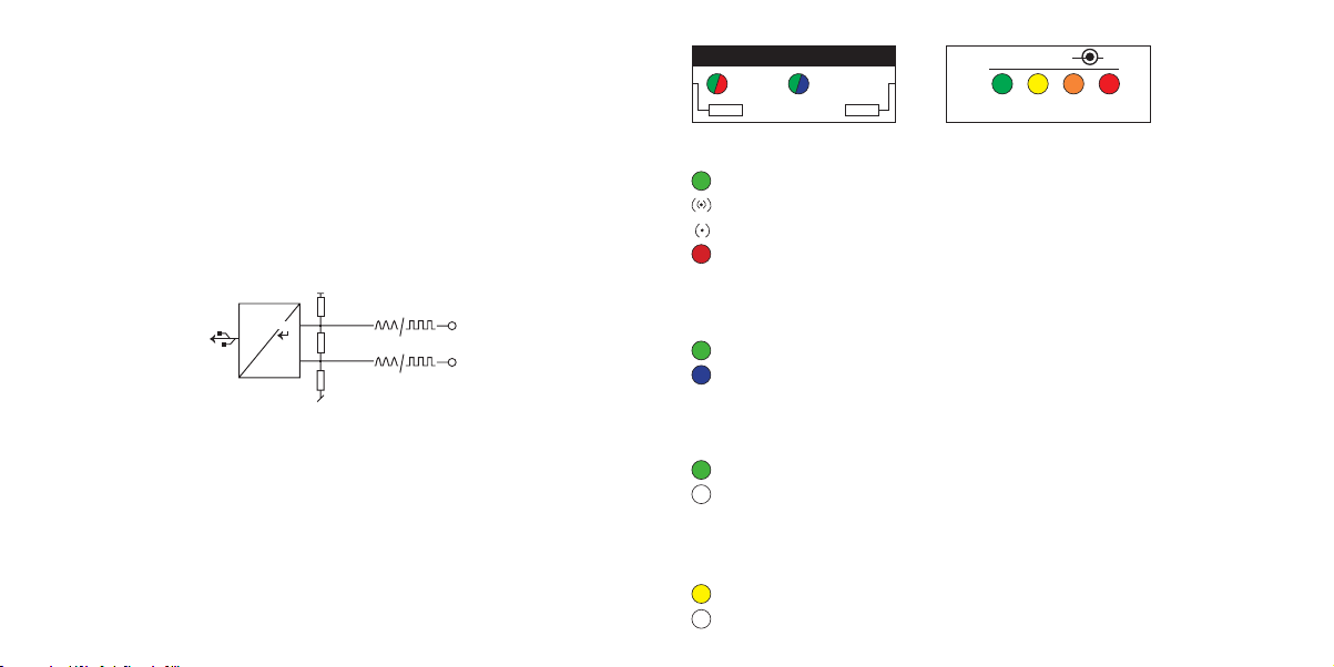
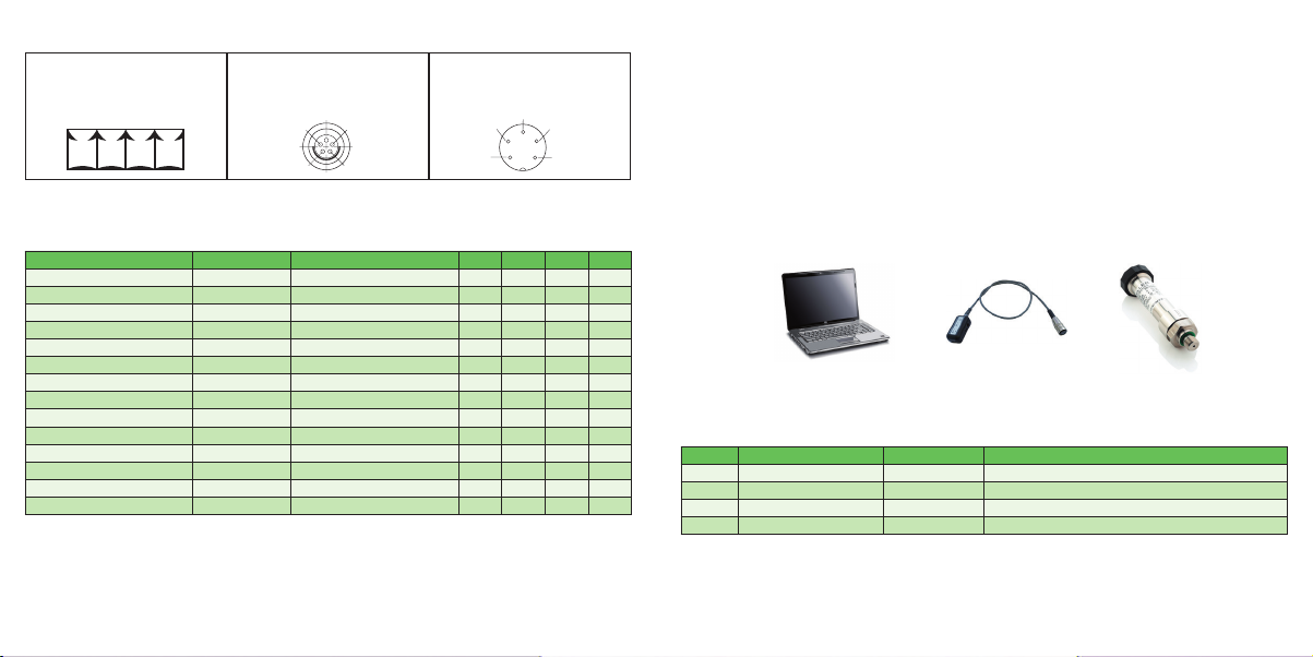
Pin assignment for converter / connections
+Vcc RS GND RS
485-A 485-B
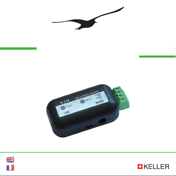
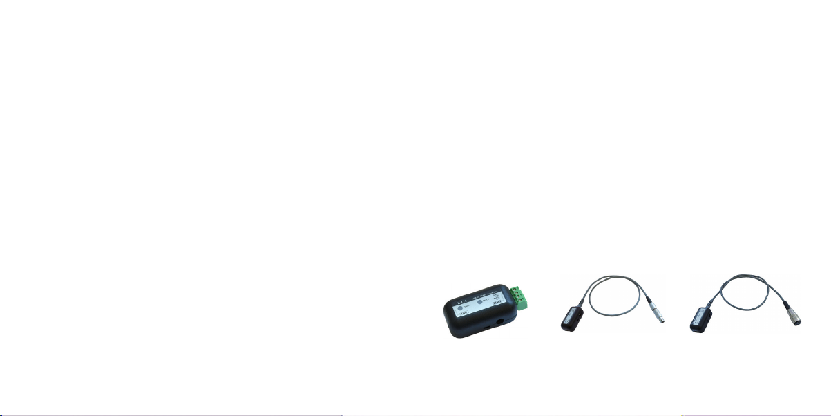
K-114
plug-in screw terminal
K-114A
Fischer plug-in connector
S 103 A054-130
K-114B
Binder female cable connector
Serie 680 5-pole
3: +Vcc
4: RS485-A
5: RS485-B
2: +U-IN
1: GND
2: +U-IN
3: +Vcc
4: RS485-A
1: GND
5: RS485-B
– 18 – – 19 –
Typical application
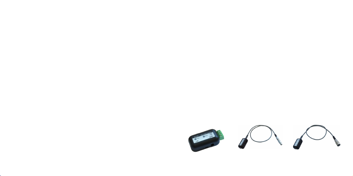
Overview of products
Product Connection Product number Products supported
K-114 Plug-in screw terminal 309010.0074 All digital KELLER products Series 3X, Series 4X, DCX*
K-114A Fischer plug 309010.0075 DCX-16 /-22-25 PVDF / -38, LEO Record, LEX 1, GSM series
K-114B Binder female cable connector 309010.0076 Series 30X / 40X, LEO 3, EV-120, dV-22 PP, dV-2 PS**, Castello**
K-114M M12 female cable connector 309010.0077 DCX-18 only (communication and charging cable)
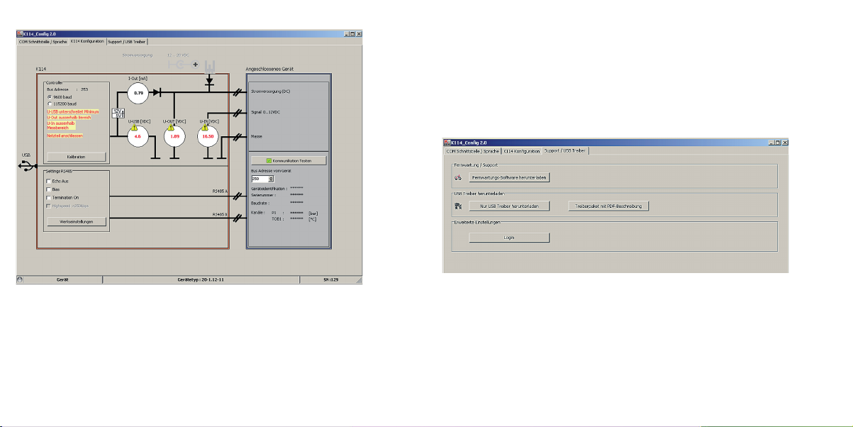
Description
The K-114 communicates with the connected devices via an RS485 (half-duplex mode) bus. The devices connected
to the K-114 are supplied via the PC’s USB output or via an external power supply unit (K-114 socket).
KELLER products operate with fail-safe drivers that generate a logical „high“ at the reception output in case of
short-circuited, open or terminated inputs, in order to avoid invalid signal statuses. KELLER products also have a
slew rate limitation which limits the edge steepness (i.e. slew rate) of the driver output. This prevents high-frequency
emissions from devices and data lines. Up to a maximum of 128 transmitters can be connected to this RS485
master bus.
* no voltage input
** requires additional cable option