manuals.online logo
Brands
  1. Home
  2. •
  3. Brands
  4. •
  5. RGBlink
  6. •
  7. Media Converter
  8. •
  9. RGBlink VSP 3500 User manual

RGBlink VSP 3500 User manual

VSP 3500 –Quick Start
Installation and cabling features
Rear Panel
Connections
10/100M Internet Control Port
5
USB Control Port
2
3
4
6
Power Switch Button
and Power Port IEC-3
Step 1-Mounting
Turn off or disconnect all equipment power sources.
VSP 3500 Quick Start
Version 1.0
Page 1 of 4
Address: S603~S604, Weiye Building, Torch Hi-Tech Industrial Development Zone, Xiamen, Fujian, China
Tel: 00865925771197 Fax:00865925771202
Email: sales@rgblink.com http://www.rgblink.cn
1Dial switch
RS232 Control Port 13
9
14
DVI Output Port DVI-I
Step 2- DVI Input DVI-I
This guide provides quick start instructions for an experienced installer to set
up and operate the VSP 3500.
DVI input ports support signal sources
of HDM I from high-definition player
or DVI from PC.
Used to connect display system with
DVI input port or LED display control
system; DVI 1 output acts as the default
program output.
NOTE
87
12
DVI Loop Out
DVI Input Port DVI-I
Step 4- DVI Output DVI-I
~
NOTE Comments to use the programs video when
connect with HDMI from high definition
player.
NOTE Comments to use the sending cards box,
Driver, DV4 from RGBlink for that VSP3500
can not support sending card installed inside.
Pin End 1
Wire color
End 2
Wire color
1 White-green White-orange
2 Green Orange
3 White-orange White-green
4 Blue Blue
5 White-blue White-blue
6 White-orange Green
7 White-brown White-brown
8 Brown Brown
Crossover Cable
CAT5 is wired as T568A at one end and T568B at the
other(Tx and Rx pairs reversed) is crossover.
T568A T568B
Insert Twisted
Pair Wires
RJ-45
Connector
Pins
Step 6-USB Port
192.168.0.100. Operator can also change the IP address
by RS 232 or USB.
Twist CAT5 should be one end in T568A, and another
end in T568B standard.
Use USB cable to connect the VSP 3500 and
computer.
For full installation, configuration, and operation details, refer to the
VSP 3500 user manual, which is available at www.rgblink.com.
VIEWSIZE THE WORLD
Step 3- DVI Loop Out
Can connect the next level VSP 3500
or the device with DVI loop out.
Step 5- Lan Control Port
Use twist CAT5 cable to connect to LAN port, operator
can control VSP 3500 based on default IP address:
VSP 3500 Quick Start
Version 1.0
Page 2 of 4
Address: S603~S604, Weiye Building, Torch Hi-Tech Industrial Development Zone, Xiamen, Fujian, China
Tel: 00865925771197 Fax:00865925771202
Email: sales@rgblink.com http://www.rgblink.cn
Step 8- Power Port
Plug in power cord which has IEC connector, VSP
3500 supports AC power from 90 to 264 VAC,50-
60Hz, which means world wide compatible.
How to set output resolution
Press MENU button, and rotate Up/Down knob to
select OUTPUT CONFIG. Press NEXT and rotate
Up/Down knob to select OUTPUT FORMAT. Press
NEXT and rotate Left/Right knob to select OUTPUT
RESOLUTION. Then press NEXT to setup.
How to add layer
Power On
Push power button switcher to ON position. LCD
module on the front panel will show RGBLINK and
VSP 3500 model information, and go into self
verification before it load the last setting configuration
data and send the processed image to the target display
or device. For the first time running, CV1 input is the
default input source.User can operate with VSP 3500
with local front panel and remote control with the
software run on the PC, remote control by RS232, USB
or TCP/IP.
RS-232 Function
2 TX Transmit
3 RX Receive
5 GND Signal Ground
7 --- Not Used
8 --- Not Used
Pin RS-422 Function
TX- Transmit(-)
RX- Receive(-)
GND Signal Ground
RX+ Receive(+)
TX+ Transmit(+)
Insert Twisted
Pair Wires
RS232/RS422
Connector
Insert Twisted
Pair Wires
RJ11 Connector
RJ-11 Function
1
TX Transmit
2 RX Receive
3
GND Signal Ground4
--- Not Used
Pin
Local Control-Front Panel Operation
In LAYERS area, choose layer that need to increase
layer, that is press any key of layer A, B, C, D (or select
all the 4 keys), key lights, then the layer is selected, and
add layer finished.
How to edit and define output
1. In OUTPUTS part, push DVI1, DVI2, DVI3, DVI4
and it will light to show it is being programmed;
OUTPUTS part DVI1 key is correspond with DVI1;
OUTPUTS part DVI2 key is correspond with DVI2;
OUTPUTS part DVI3 key is correspond with DVI3;
OUTPUTS part DVI4 key is correspond with DVI4;
2. In FUNCTIONS part, push Scale to adjust the size
of image which means to zoom in/out of the image;
3. In CUSTOM ADJUSTMENTS part, push Crop to
crop the image which means to crop the input signal
of the output screen;
4. In CUSTOM ADJUSTMENTS part, push Position
to adjust the position of the corresponding input
image of the layer which means to adjust the
position of output screen.
Step 7- Serial Port
Use RS232 to RJ11 cable to connect a control system
or computer to the back panel RJ11 port and the other
end on RS232 port. RS232 to RJ11 cable as following
definition.
VSP 3500 supports output resolution as
following:
NOTE
1024×768×60Hz, 1280×720×60Hz,1280×768×60Hz,
1280×1024×60Hz,1360x768x60Hz,1366x768x60Hz,
1400x1050x60Hz,1440x900x60Hz,1600×1200×60Hz,
1680x1050x60Hz,1920×1080×60Hz,1920x1200x60Hz,
2048x1152x60Hz;
How to clear layer
1. In LAYER area, press any key of layer A, B, C, D
that need to clear, key blinks,
2. Press the key again, key light is off, and clear layer
finished.
How to scale the layer image
1. In CUSTOM ADJUSTMENTS area, press 【SCALE】
key, key lights, and start the scale function;
2. In LAYER area, press any bright key of A, B, C, D
(light key among layer key is optional), key lights, and
it can be edited;
3. Rotate the up/down knob to adjust window width;
Rotate the left/right knob to adjust window height;
4. Press 【SCALE】 key again, key light is off, and
close the scale function.
How to crop the layer image
1. In CUSTOM ADJUSTMENTS area, press【CROP】
key, key lights, and start crop the layer image function;
2. In LAYER area, press any bright key of A, B, C, D
(keys light are optional ), key lights, and it can be edited;
3. Rotate left/right knob, and choose the menu options;
4. Rotate left/right knob, and adjust the optional value;
5. Press【CROP】key again, key light is out, and close
crop function.
How to set the position of layer image
1. In CUSTOM ADJUSTMENTS area, press 【Position】
key, key lights, and start the set the position of layer
image function;
VSP 3500 Quick Start
Version 1.0
Page 3 of 4
How to save the parameters
When VSP 3500 function setting is finished, VSP
3500 supports 10 saving modes to avoid resetting of
the same steps.
1. Press 【SAVE】 key, key lights, and meanwhile
button 0~9 light, start the save option:
2. Choose the corresponding position and save. SAVE
TO 1 ~SAVE TO 9 corresponding button 1~9,
SAVE TO 10 corresponding button 0.
Address: S603~S604, Weiye Building, Torch Hi-Tech Industrial Development Zone, Xiamen, Fujian, China
Tel: 00865925771197 Fax:00865925771202
Email: sales@rgblink.com http://www.rgblink.cn
Save 1 is the default mode for loading to
use when VSP 3500 is power on.
NOTE
How to load the saved parameters
When VSP 3500 function setting is finished, VSP 3500
supports 10 saved modes to avoid resetting of the same
steps. All those 10 save modes can be loaded to use.
1. Press 【LOAD】 key, key lights, and meanwhile
button 0~9 light, start the load option:
2. Choose the corresponding position and load. LOAD
FROM 1 ~LOAD FROM 9 corresponding button
1~9, LOAD FROM10 corresponding button 0.
2. In LAYER area, press any bright key of A, B, C, D
(keys light are optional), key lights, and it can be
edited;
3. Rotate left/right knob to adjust window level
position, and rotate up/down knob to adjust window
vertical position;
4. Press 【Position】 key again, key lights is off and
close the set the position of layer image function.
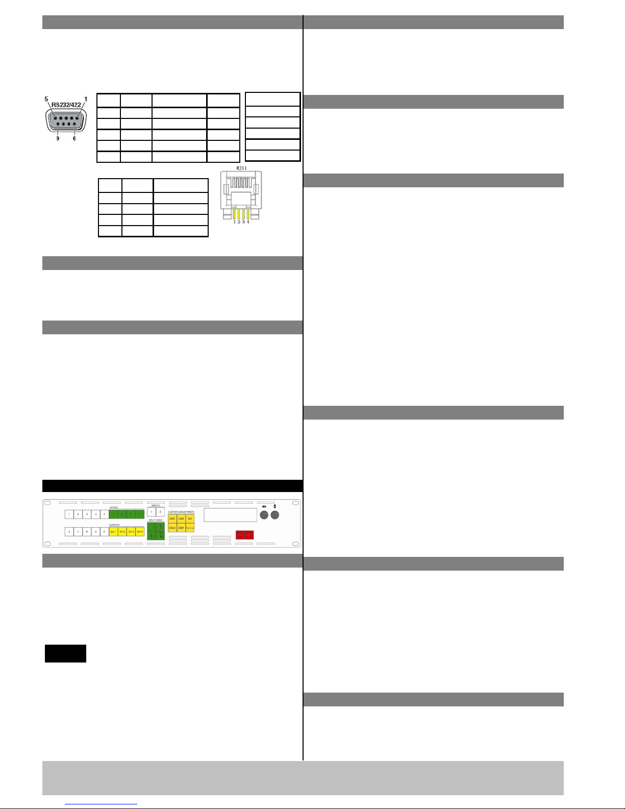
How to achieve split function
1. In SPLIT MODE area, press any key, key lights,
then start the output split function;
2. VSP 3500 provides 8 kinds of split modes for user,
rotate left/right knob to select the split mode
according to actual demand;
3. In OUTPUTS area, press any key of DVI1, DVI2,
DVI3, DVI4, select preset output, key lights, and it
is selected;
4. In CUSTOM ADJUSTMENTS area, press
【 SCALE 】 key and 【 Position 】 key , key
lights, user can set the size and position of output
image;
5. Rotate left/right knob and up/down knob, user can
set the size and position of output image;
6. In OUTPUTS area, press DVI1, DVI2, DVI3, DVI4
again, regulate the selected output, repeat step 4 and
5 to complete regulation setting.
How to rotate layer image
1. Press MENU key, choose 【LAYER CONFIG】
option.
2. Press NEXT, and enter to Layer A.
3. Press NEXT again, and enter SET ROTATE.
4. Press NEXT, choose SET ROTATE, rotate
LEFT/RIGHT knob to choose rotate mode.
5. LCD panel shows rotate mode, VSP 3500 provides
2 kinds of rotate modes for user, that is image rotate
to left or right.
When VSP 3500 is in split mode, it only split
for A layer, and is invalid for other layers.
NOTE Rotate effects setting is only for Layer A,
and are invalid for other layers.
NOTE
How to achieve quick split
There are single device split and multiple split modes,
specific operations are as follows:
1. For multiple split mode, first press MENU button,
and choose “OUTPUT CONFIG” option, rotate
the knob, choose “EXTERNAL SYNC”. Note: If
choose “EXTERNAL SYNC”, the output
resolutions should be the same.
2. Press any key in SPLIT MODE area, and choose
split modes.
3. Rotate the knob, choose “START X” and
“START Y” option (The horizontal starting
position and vertical starting position that current
device corresponding screen area in the entire LED
display).
4. Rotate the knob again to set “START X” and
“START Y”.
5. When finish, press 【SAVE】 key to save.
Here we will take field glyph mode with two devices
for example:
Total screen width 5128, total screen height 1536, the
width of the four screens are 1440, 1632, 1344, 712,
and height is 896, 640, settings are as follows:
Field glyph split on left side:
Total screen width is 5128, total screen height is1536,
the width of the first screen is1440, the height of the
first screen is 896.
Then Start X is 0, Start Y is 0.
Field glyph split on right side:
Total screen width is 5128, total screen height is1536,
the width of the first screen is1344, the height of the
first screen is 896.
Then Start X is1440+1632=3072, and Start Y is 0.
VSP 3500 Quick Start
Version 1.0
Page 4 of 4
Address: S603~S604, Weiye Building, Torch Hi-Tech Industrial Development Zone, Xiamen, Fujian, China
Tel: 00865925771197 Fax:00865925771202
Email: sales@rgblink.com http://www.rgblink.cn
Display blinks
Check if preview output is normal: Get a monitor
with VGA or DVI port and connect to the device
output port, check if the monitor displays normally;
If no blinks, check if DVI output plugs tight or
change the DVI cable that connects sending card, if
the monitor blinks, please check if input signal,
input connecting cable and input port are normal.
Display only shows part of the image
Scale the image: Press 【Scale】, rotate the knob to
adjust the size of screen, including width, height and
starting position, press 【Next】to confirm.
Display shows no bottom half part
Incorrect output resolution: Confirm the width and
height point on the screen, and select more adequater
resolution than screen width, press 【Next】 to
confirm.
Black edge appears on left or top
Adjust device DVI output DE excursion, press
MENU, select XY_POS, press the knob to confirm, if
LED screen top part appears black edge, adjust V_S
Assure there are output signals: Get a monitor with
VGA or DVI port, connect it to device output port,
see if the monitor can display normally. If unnormal,
check if the input signals are connected or if the
output cable contacts good.
FAQ solutions
Display has no output image
Assure there are input signals: Press【MENU】
and go into【Device Info】, press the knob to cofirm,
check the input signal sources, if appear <NO
INPUT>, please check the connection; If use PC DVI
or VGA as signal source, please set the display card
to dual display or expanding mode;
Factory Reset: When there is wrong operation during
parameter adjustment, users can recall the device and
readjust the parameter. Following the steps: Press
MENU button ,choose the submenu Reset and press
NEXT to initiate factory reset.
All buttons light on together
Check if the dial switch is normal;
Power off the device, check if two red dial switches
on back left part of the device are all upwards, if not,
place them upwards, then power on the device again.
The red dial switches are mainly for upgrade.
via rotate the knob; if LED screen left part appears
black edge, adjust H_S via rotate the knob. After
setting, please save the parameter to SAVE1.

Other RGBlink Media Converter manuals

RGBlink VSP 198CVS User manual

RGBlink

RGBlink VSP 198CVS User manual

RGBlink Q16pro Gen2 1U User manual

RGBlink

RGBlink Q16pro Gen2 1U User manual

RGBlink MSP Series User manual

RGBlink

RGBlink MSP Series User manual

RGBlink TAO 1pro User manual

RGBlink

RGBlink TAO 1pro User manual

RGBlink MSP 202 User manual

RGBlink

RGBlink MSP 202 User manual

RGBlink MSP 200PRO User manual

RGBlink

RGBlink MSP 200PRO User manual

RGBlink M1 User manual

RGBlink

RGBlink M1 User manual

RGBlink GX4 User manual

RGBlink

RGBlink GX4 User manual

RGBlink UMS4 pro User manual

RGBlink

RGBlink UMS4 pro User manual

RGBlink VENUS X1PRO User manual

RGBlink

RGBlink VENUS X1PRO User manual

RGBlink FLEX 8 User manual

RGBlink

RGBlink FLEX 8 User manual

RGBlink MSP 204 User manual

RGBlink

RGBlink MSP 204 User manual

RGBlink FLEX RS1 User manual

RGBlink

RGBlink FLEX RS1 User manual

RGBlink FLEX RS1 User manual

RGBlink

RGBlink FLEX RS1 User manual

RGBlink TAO 1pro-S User manual

RGBlink

RGBlink TAO 1pro-S User manual

RGBlink MSP 325N User manual

RGBlink

RGBlink MSP 325N User manual

RGBlink FLEX 32 User manual

RGBlink

RGBlink FLEX 32 User manual

RGBlink VSP 310 User manual

RGBlink

RGBlink VSP 310 User manual

RGBlink FLEXpro 8 User manual

RGBlink

RGBlink FLEXpro 8 User manual

RGBlink VSP268S User manual

RGBlink

RGBlink VSP268S User manual

RGBlink VSP 628 User manual

RGBlink

RGBlink VSP 628 User manual

RGBlink VENUS X1 User manual

RGBlink

RGBlink VENUS X1 User manual

RGBlink IC2+ User manual

RGBlink

RGBlink IC2+ User manual

RGBlink CP 3072PRO User manual

RGBlink

RGBlink CP 3072PRO User manual

Popular Media Converter manuals by other brands

tams elektronik LD-G-24 manual

tams elektronik

tams elektronik LD-G-24 manual

Kramer VP-475UX quick start guide

Kramer

Kramer VP-475UX quick start guide

K & K Audio Extreme RAKK Mark III Assembly manual

K & K Audio

K & K Audio Extreme RAKK Mark III Assembly manual

Ask DVISP002M1 user manual

Ask

Ask DVISP002M1 user manual

ACTi ACD-3100 user manual

ACTi

ACTi ACD-3100 user manual

Cypress CV-401H Operation manual

Cypress

Cypress CV-401H Operation manual

Snell Advanced Media MV-800 user manual

Snell Advanced Media

Snell Advanced Media MV-800 user manual

COBHAM SAILOR 6090 installation guide

COBHAM

COBHAM SAILOR 6090 installation guide

Vanco RS232-IP manual

Vanco

Vanco RS232-IP manual

Chord MOJO 2 Product guide

Chord

Chord MOJO 2 Product guide

Intellinet IMC-SMSCF20KM-WDMA instruction manual

Intellinet

Intellinet IMC-SMSCF20KM-WDMA instruction manual

DVIGear DVI-3130a user guide

DVIGear

DVIGear DVI-3130a user guide

Datacom Systems 1000BT-AT+7C installation guide

Datacom Systems

Datacom Systems 1000BT-AT+7C installation guide

GeoVision GV-IP quick start guide

GeoVision

GeoVision GV-IP quick start guide

Lumagen Radiance2021 owner's manual

Lumagen

Lumagen Radiance2021 owner's manual

Texas Instruments ADS79 EVM-PDK Series manual

Texas Instruments

Texas Instruments ADS79 EVM-PDK Series manual

Siemens SINAMICS G120D operating instructions

Siemens

Siemens SINAMICS G120D operating instructions

CYP CP-261H Operation manual

CYP

CYP CP-261H Operation manual

manuals.online logo
manuals.online logoBrands
  • About & Mission
  • Contact us
  • Privacy Policy
  • Terms and Conditions

Copyright 2025 Manuals.Online. All Rights Reserved.