Nexans XPLORER Series User manual
NOTICE / INSTRUCTIONS
Tous les schémas, dessins, spécifications, plans et détails de poids, tailles et dimensions figurant dans la
documentation technique ou commerciale de Nexans ont un caractère purement indicatif et ne sauraient
engager Nexans ou être traités comme constitutifs d’une garantie de la part de Nexans.
All drawings, designs, specifications, plans and particulars of weights, size and dimensions contained in the
technical or commercial documentation of Nexans is indicative only and shall not be binding on Nexans or be
treated as constituting a representation on the part of Nexans.
Document : ABS1542/A
Date : 12/03/2019
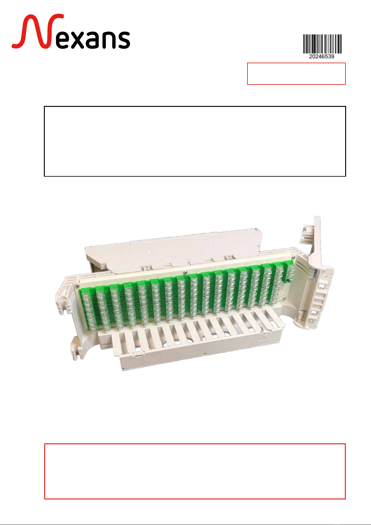
XPLORER™3U - 128FO COUPLAGE (SC ET LC)
XPLORER™3U - 128OF SPLITTER (SC AND LC)

ABS1542/A
Table des matières
2/30
XPLORER™
Table Of Contents
1. DESCRIPTION
OVERVIEW .......................................................................................................4
1.1. PRÉSENTATION DU PRODUIT
PRODUCT PRESENTATION ........................................................................................4
1.2. CARACTÉRISTIQUES TECHNIQUES
TECHNICAL CHARACTERISTICS .................................................................................5
1.3. KITS FOURNIS
PROVIDED KITS.........................................................................................................6
2. FIXATION DU MODULE
FIXATION OF THE MODULE.............................................................................7
2.1. CONDITIONNEMENT
PACKAGING............................................................................................................. 7
2.2. MISE EN PLACE DU DORMANT
INSTALLING THE FIXED CHASSIS ...............................................................................9
2.3. MISE EN PLACE DE LA PLAQUE DE VERROUILLAGE
INSTALLING THE LOCKING PLATE...........................................................................10
2.4. MISE EN PLACE DU BATTANT
INSTALLING THE SWIVELING CHASSIS ....................................................................11
3. RACCORDEMENT DU MODULE
CONNECTION OF THE MODULE...........................................................................12
3.1. RACCORDEMENT PAR BRASSAGE
CONNECTION BY PATCHING.................................................................................12
3.2. RACCORDEMENT PAR ÉPISSURAGE
CONNECTION THROUGH SPLICING ......................................................................13
3.2.1. ACCÈS À L’ORGANISEUR
ACCESS TO THE ORGANISER .....................................................................13
3.2.2. PRÉPARATION DU CÂBLE OU DU PIGTAIL
CABLE OR PIGTAIL PREPARATION............................................................... 14
3.2.3. FIXATION ARRIÈRE DU PIGTAIL, MICROMODULE OU LOOSETUBE
LOOSETUBE, MICROBUNDLE OR PIGTAIL BACK FIXATION..........................15
3.2.4. CHEMINEMENT DES TRONCS DES COUPLEURS
ROUTING OF SPLITTERS INPUTS.................................................................16
3.2.5. CHEMINEMENT DES FIBRES JUSQU’À L’ORGANISEUR
ROUTING FIBRES INTO THE ORGANISER....................................................18
4. FERMETURE DU BATTANT
CLOSING THE SWIVELING CHASSIS ..............................................................20
5. POSE D’UN CORDON
INSTALLING PATCHCORD ..............................................................................21

ABS1542/A 3/30
XPLORER™
6. ÉLÉMENTS PARTICULIERS DE MAINTENANCE
SPECIAL PROCEDURES FOR MAINTENANCE ..................................................22
6.1. REMPLACEMENT D’UN RACCORD
ADAPTER REPLACEMENT......................................................................................... 22
6.2. PRINCIPE DE DÉPOSE DU MODULE
MODULE REPLACEMENT......................................................................................... 23
6.3. REMPLACEMENT D’UN COUPLEUR
SPLITTER REPLACEMENT.......................................................................................... 24
7. ANNEXES
ANNEX...........................................................................................................26
7.1. AUTRES KITS À APPROVISIONNER EN SUPPLÉMENT
OTHERS KITS TO BE ORDERED SEPARATELY ............................................................26
7.2. FIXATION AVEC ÉCROUS CAGES SUR MONTANTS 19’’
CAGE NUTS FIXATION ON 19’’ FRAMES .................................................................27
7.3. FIXATION DU KIT DE GUIDAGE
ROUTING KIT FIXATION.......................................................................................... 28
8. INSTRUCTION DE FIN DE VIE
END LIFE INSTRUCTION.................................................................................30
9. TRAÇABILITÉ
TRACEABILITY.................................................................................................30
10
ABS1542/A 4/30
XPLORER™
1. DESCRIPTION
OVERVIEW
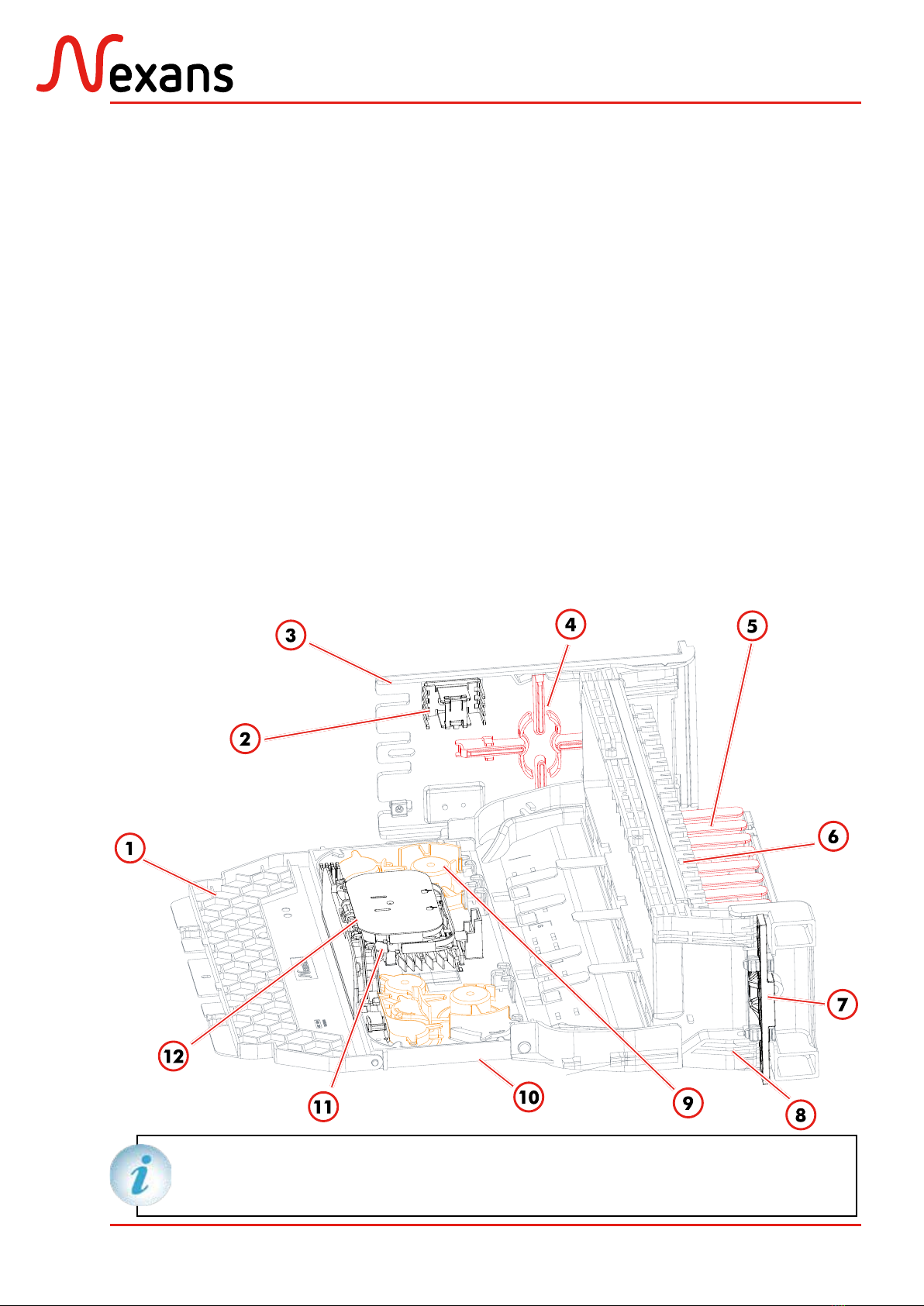
1.1. Présentation du produit
Product presentation
1- Protective cover
2- Fixation comb
3- Fixing bracket (fixed chassis)
4- Coiling area
5- Support for patchcords management
6- Front patch panel (128 OF)
7- Locking plate
8- Swiveling chassis
9- Routing elements
10- Rotating back plate for routing of optical
fibres
11- Lower cassette (12 splices)
12- Upper cassette (12 splices)
1- Capot de protection
2- Peigne de fixation
3- Équerre de fixation (dormant)
4- Zone de lovage
5- Goulotte pour la gestion des cordons
6- Panneau frontal de brassage (128 FO)
7- Plaque de verrouillage
8- Ensemble optique pivotant (battant)
9- Éléments de guidage
10- Platine articulée de raccordement
11- Cassette inférieure (12 épissures)
12- Cassette supérieure (12 épissures)
Les schémas représentent un module
axe à droite, cablé avec coupleur 1:32.
The drawings represent a right axis
module, cabling with 1:32 splitter.

ABS1542/A 5/30
XPLORER™
1.2. Caractéristiques techniques
Technical characteristics
–Weight: 3kg
–Height: 3U
–Width: 19”/ETSI standard
–Depth: 185mm
– Poids : 3kg
– Hauteur : 3U
– Largeur : Standard 19”/ETSI
– Profondeur : 185mm
230mm
185mm
3U
19’’
38mm
ETSI
ABS1542/A 6/30
XPLORER™
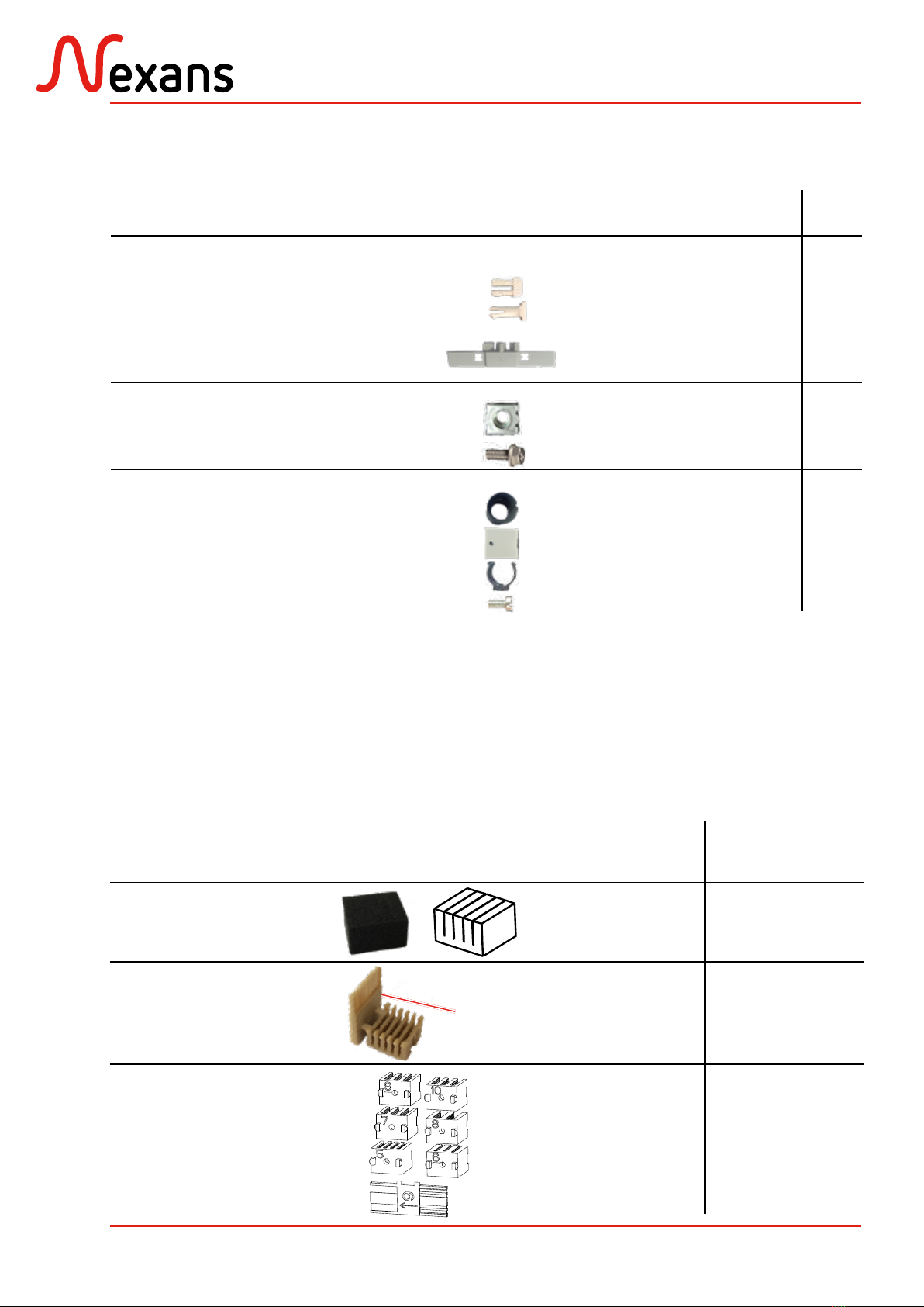
1.3. Kits fournis
Provided kits
Listedespeignesfournis etdiamètred’utilisation Combs list and fitting diameter
Numéro du peigne
Comb number
Ø des tubes ou pigtails
Ø of tubes or pigtails
Qté
Qty
Peigne en mousse
Foam comb Ø 250μm 1
Peigne pour pigtails
Pigtails comb Ø 900μm 2
Peignes en plastique
#5 à #10
Plastic combs
#5 to #10
#5 - Ø 900μm
#6 - Ø 1.6mm
#7 - Ø 2.4mm
#8 - Ø 4mm
#9 - Ø 2mm
#10 - Ø 2.8mm
1
1
1
1
1
1
Outil
Tool
Description Qté /
Qty
Kit de fixation 19’’ standard
(£↕9,5mm) :
– Douilles
– Pions
– Plaque de verrouillage 19’’ 3U
Standard 19’’ fixation kit
(£↕9.5mm):
–Sockets
–Pawns
–Locking plate 19’’ 3U
5
5
1
Kit de fixation 19’’ (£↕8,3mm) :
– Écrous cages (£↕8,3mm)
– Vis hexagonales à embase
19’’ fixation kit (£↕8.3mm):
–Cage nuts (£↕8.3mm)
–Hexagonal base screws
5
5
Kit bobine :
– Anneau bobine (Ø 50 mm)
– Support bobine
– Clip bobine
– Vis cylindrique large fendue
Spool kit:
–Spool (Ø 50 mm)
–Spool support
–Spool clip
–Cylindrical slotted head
1
1
1
1
a
b
c
d
e
f
g
h
i
Outil
Tool

ABS1542/A 7/30
XPLORER™
2. FIXATION DU MODULE
FIXATION OF THE MODULE
2.1. Conditionnement
Packaging
Dormant
Fixed chassis
Battant
Swiveling chassis
Accessoires
Accessories
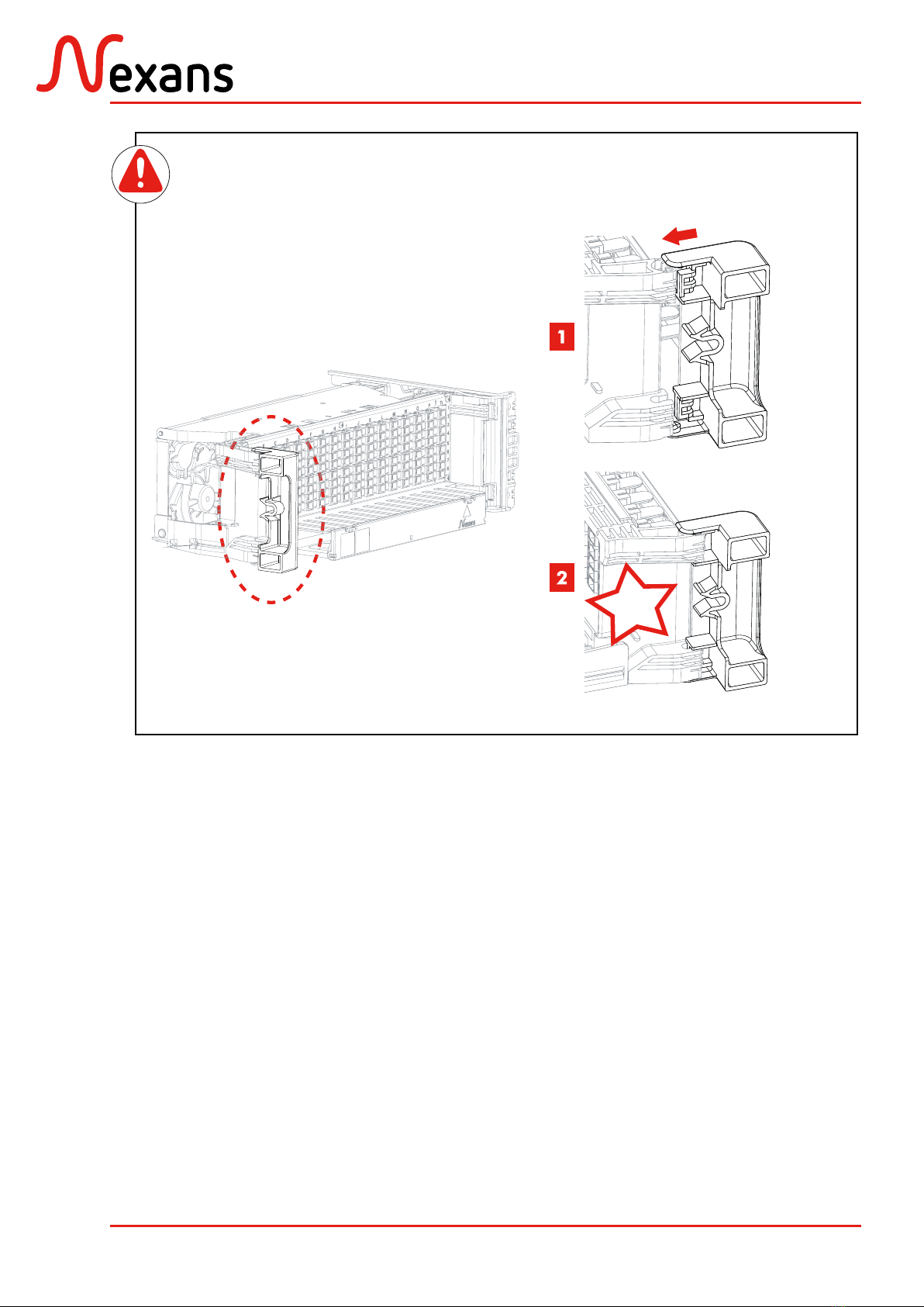
Loquet
Lock
ABS1542/A 8/30
XPLORER™
Click
Mise en place du loquet côté
opposé de l’axe de rotation. Installing the lock to the opposite of
the rotation axis.

ABS1542/A 9/30
XPLORER™
Kit de fixation 19’’ standard
(£↕9,5mm).
Standard 19’’ fixation kit (£↕9.5mm).
x5 x5 3U
2.2. Mise en place du dormant
Installing the fixed chassis
19’’
9.5mm
Oui/Yes
Standard
Standard
Dimension carrés
Squares dimension
Anneaux intégrés
Integrated spools
a b c
Si l’armoire n’est pas conforme au
standard 19’’ £↕9,5mm, se reporter
au chapitre 7 (annexes).
If the cabinet is not compliant with
the 19’’ £↕9,5mm standard, refer to
the chapter 7 (annex).
Enlever les appendices des pions
et des douilles.
Remove the links between sockets
and pawns.
Mise en place des douilles (b). Installing sockets (b).
Montant avant gauche
Left front frame
Click
Position de la douille et du
pion sur le montant avant
(gauche et droit).
Position of the socket and the
pawn in the front frame (left
and right).
Click

ABS1542/A 10/30
XPLORER™
Click
Sens de la douille et du pion
sur le montant arrière.
Position of the socket and the
pawn in the back frame.
Montant arrière
Back frame
Mise en place des pions(b). Installing pawns (b).
Montant arrière
Back frame
Montant avant gauche
Left front frame
2.3. Mise en place de la plaque de verrouillage
Installing the locking plate
Montant avant droit (b + c)
Right front frame (b + c)
Montant avant droit (a)
Right front frame (a)
Click
Click
ABS1542/A 11/30
XPLORER™
Click
Ne pas déclipper le battant après
la mise en place.
Do not unclip the swiveling chassis
after the installation.
90°
90°
Angle de montage repéré par un index moulé
Mounting angle marked by molded index
2.4. Mise en place du battant
Installing the swiveling chassis
Click
Click
ABS1542/A 12/30
XPLORER™
Click
3. RACCORDEMENT DU MODULE
CONNECTION OF THE MODULE
3.1. Raccordement par brassage
Connection by patching
Refermer le battant
Close the swiveling chassis
S’assurer du bon verrouillage
Ensure to correct locking
Coupleur : connection réseau par brassage
Splitter: network connection by patching
Par défaut le produit est livré avec des troncs préconnectorisés
As a standard the product is delivered with preterminated input
Tronc préconnectorisé
Preterminated input
Branche
Output
Coupleur
Splitter

ABS1542/A 13/30
XPLORER™
3.2. Raccordement par épissurage
Connection through splicing
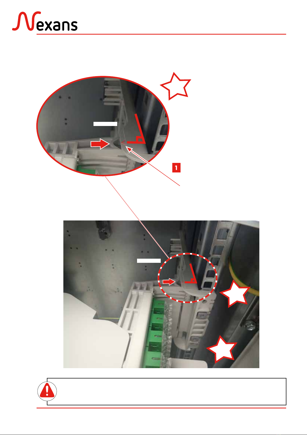
3.2.1. Accès à l’organiseur
Access to the organiser
Emplacement des troncs
Inputs location
1
2
3
4
5
6
7
8
Tronc
Input
Cordon
Patchcord
Click
Veiller à bien dégager les
ergots pour l’ouverture
Ensure to clear out the ergots
for the opening.
105°
Déclipper le capot
Unclip the cover
Ouvrir le battant
Open the swiveling chassis

ABS1542/A 14/30
XPLORER™
Cas 2: préparation d’un câble
Case 2: preparation of a cable
Voir la notice du système d’épanouissement. Refer to the clamping device instructions.
Peigne métallique
Metallic comb
Cas 1 : préparation d’un pigtail
Case 1: preparation of a pigtail
60mm 1500mm minimum
Pigtail
Pigtail
Peigne métallique
Metallic comb
3.2.2. Préparation du câble ou du pigtail
Cable or pigtail preparation
Faire pivoter la platine
Rotation of the plate

ABS1542/A 15/30
XPLORER™
Tube Ø 5mm 1500mm minimum
Micromodule
Microbundle
Peigne métallique
Metallic comb
Fibres nues
Bare fibres
Peigne métallique
Metallic comb
1000 mm en sortie de loosetube
Préparation du micromodule
Preparation of the microbundle
Préparation du loosetube
Preparation of the loosetube
3.2.3. Fixation arrière du pigtail, micromodule ou loosetube
Loosetube, microbundle or pigtail back fixation
Maintenir les pigtails
Maintain the pigtails
Pigtails
Pigtails
Tube Ø 5mm
Peigne métallique
Metallic comb
Cas 1 : fixation d’un pigtail
Case 1: fixation of the pigtail
ABS1542/A 16/30
XPLORER™
Micromodule ou loosetube
Microbundle or loosetube
Tube Ø 5mm
Cas 2: fixation d’un micromodule ou loosetube
Case 2: fixation of the microbundle or loosetube
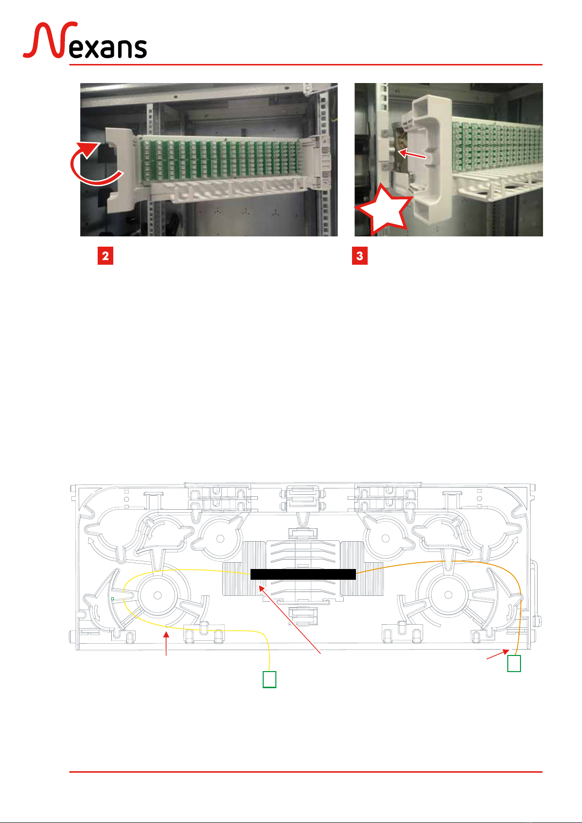
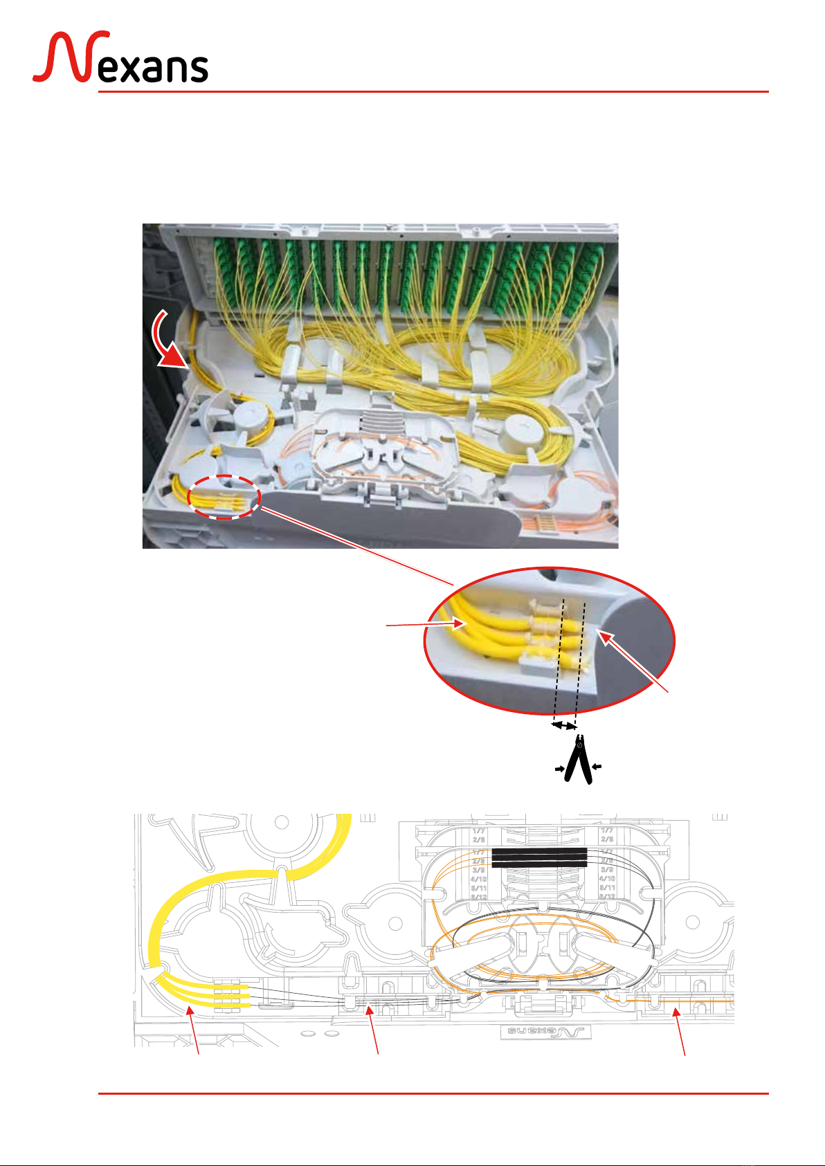
3.2.4. Cheminement des troncs des coupleurs
Routing of splitters inputs
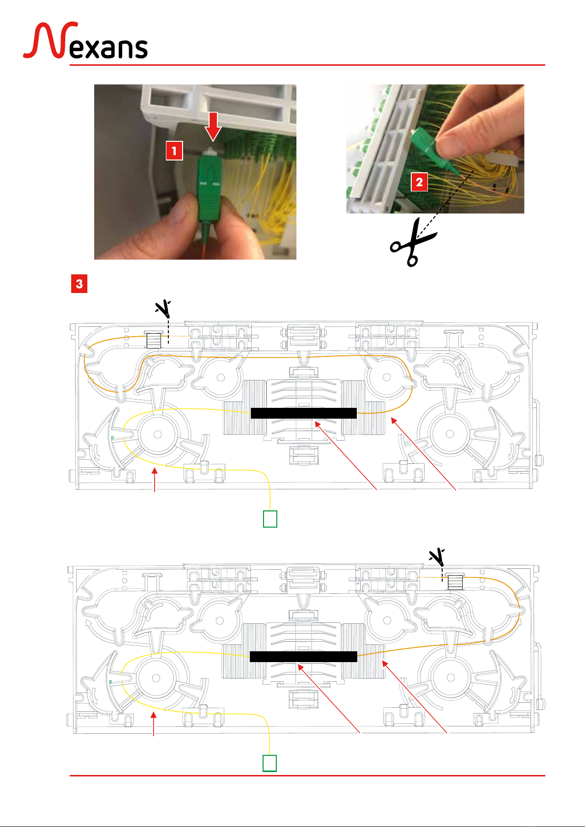
1- Disconnect the splitter input
2- Cut the connector
3- Routing the splitter input to the splice
cassette as in the following drawings
1- Déconnecter le tronc du coupleur
2- Couper la fiche
3- Router le tronc du coupleur jusqu’à la
cassette
Tronc préconnectorisé
Preterminated input
Branche
Output
Coupleur
Splitter
ABS1542/A 17/30
XPLORER™
Cheminement des troncs: cas d’un tronc à souder pour un tiroir monté avec un axe à gauche
Routing of inputs: case of an input to be splice for a right axis module
Tronc
input
Branche
Output
Coupleur
Splitter
Cheminement des troncs: cas d’un tronc à souder pour un tiroir monté avec un axe à droite
Routing of inputs: case of an input to be splice for a left axis module
Tronc
input
Branche
Output
Coupleur
Splitter
ABS1542/A 18/30
XPLORER™
Pigtails
Pigtails
Fibres nues raccordées (cassette supérieure)
Connected bare fibres (upper cassette)
Tronc
Input
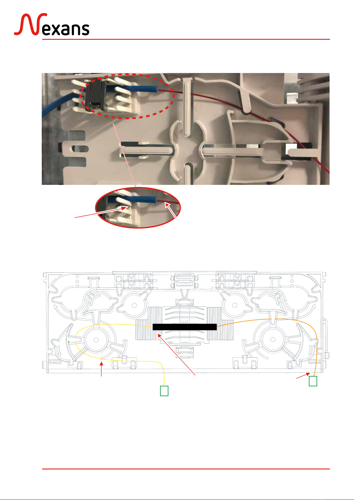
3.2.5. Cheminement des fibres jusqu’à l’organiseur
Routing fibres into the organiser
Pigtails
Pigtails
Fibres nues
Bare fibres
Vue d’ensemble du câblage
Cabling overview
Cas 1 avec les pigtails
Case 1 with the pigtails

ABS1542/A 19/30
XPLORER™
Outil
Tool
Peignes en mousse
ou pour tubes
Foam or tubes
combs
Peigne pour pigtails
Pigtails comb
Fibres nues raccordées
Connected bare fibres
Tronc
Intput
Micromodule ou loosetube
Microbundle or loosetube
Fibres nues non raccordées
Unconnected bare fibres
Réaliser l’épissure
(compatibilité: 40mm, 45mm, 60mm)
Perform the splice
(compatibility: 40mm, 45mm, 60mm)
Cas 2 avec les micromodules ou loosetubes
Case 2 with the microbundles or loosetubes
ABS1542/A 20/30
XPLORER™
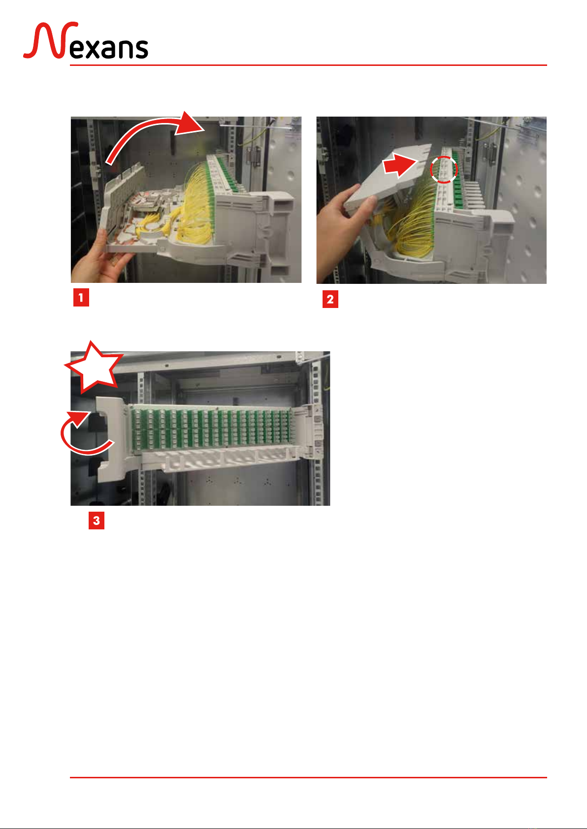
4. FERMETURE DU BATTANT
CLOSING THE SWIVELING CHASSIS
Rabattre la platine et son capot
Rotate the plate and the cover
Clipper le capot et resserrer la vis
Clip the cover and tighten the screw
Refermer le battant
Close the swiveling chassis
Click
Other manuals for XPLORER Series
2
This manual suits for next models
1
Table of contents
Other Nexans Media Converter manuals


