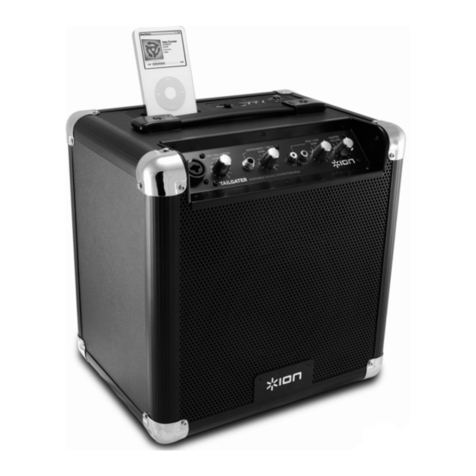
DIGITECH Audio CS-2484 User manual

12 15 ″ powered loudspeaker″
CS-2484 /CS-2486
CS-2484 CS-2486
Pole Mounting :This series also include a pole mount option. The
pole mount socket located on the bottom of the speaker may be
used to secure the speaker to a speaker tripod. Always be sure to
fellow the guidelines listed be blow when pole mounting your speaker.
1. Always be sure the stand is designed to support the weight of the
speaker
2.In outdoor situations that are prone to windy conditions and strong
wind gust , be sure to use sandbags as additional tripod support ,
this will greatly reduce the risk of tipping
3.Do not stack speakers on top of each other when mounting on a
tripod. Only one speaker should be mounted to a tripod at one time
4.Always position the tripod legs away from foot traffic
5.Extend the tripod legs to their fully extended position to avoid
accidental tipping
6.Observe and follow all safety guidelines and regulations specified
by the tripod manufacturer
7.Be sure the tripod is situated on a flat ,level , and stable surface
8.Always tighten all tripod locks
OWNER`S MANUAL
Distributed by:
TechBrands by Electus Distribution Pty.Ltd.
320 Victoria Rd, Rydalmere
NSW 2116 Australia
Ph: 1300 738 555
Int`1: +61 2 8832 3200
Fax: 1300 738 500
www.techbrands.com

1
The symbol is used to indicate that some hazardous live terminals are involved within this apparatus, even
under the normal operating conditions, which may be sufficient to constitute the risk of electric shock or
death.
The symbol is used in the service documentation to indicate that specific component shall be replaced
only by the component specified in that documentation for safety reasons.
Protective grounding terminal
Alternating current/voltage
Hazardous live terminal
ON: Denotes the apparatus is turned on
OFF: Denotes the apparatus is turned off.
WARNING: Describes precautions that should be observed to prevent the danger of injury or death to the operator.
CAUTION: Describes precautions that should be observed to prevent danger of the apparatus.
1. IMPORTANT SAFETY INSTRUCTIONS
·Read these instructions.
·Keep these instructions.
·Heed all warning.
·Follow all instructions.
·Water & Moisture
The apparatus should be protected from moisture and
rain, can not used near water, for example: near bath-
tub, kitchen sink or a swimming pool, etc.
·Heat
The apparatus should be located away from the heat
source such as radiators, stoves or other appliances
that produce heat.
·Ventilation
Do not block areas of ventilation opening. Failure to
do could result in fire. Always install accordance with
the manufacturer's instructions.
·Object and Liquid Entry
Objects do not fall into and liquids are not spilled into
the inside of the apparatus for safety.
·Power Cord and Plug
Protect the power cord from being walked on or pinched
particularly at plugs, convenience receptacles, and the
point where they exit from the apparatus.
Do not defeat the safety purpose of the polarized or
grounding-type plug. A polarized plug has two blades
with one wider than the other. A grounding type plug
has two blades and a third grounding prong. The wide
blade or the third prong is provided for your safety.
If the provided plug does not fit into your outlet, refer
to electrician for replacement.
CAUTION
RISK O F EL ECTRI C SH OCK
DO NOT O PE N
IMPORTANT SAFETY SYMBOLS
°
·Power Supply
The apparatus should be connected to the power supply
only of the type as marked on the apparatus or described
in the manual. Failure to do could result in damage to the
product and possibly the user.
Unplug this apparatus during lightning storms or when
unused for long periods of time.
Where the MAINS plug or an appliance coupler is used as
the disconnect device, the disconnect device shall remain
readily operable.
·Fuse
To prevent the risk of fire and damaging the unit, please
use only of the recommended fuse type as described in
the manual. Before replacing the fuse, make sure the unit
turned off and disconnected from the AC outlet.
·Electrical Connection
Improper electrical wiring may invalidate the product war-
ranty.
·Cleaning
Clean only with a dry cloth. Do not use any solvents such
as benzol or alcohol.
·Servicing
Do not implement any servicing other than those means
described in the manual. Refer all servicing to qualified
service personnel only.
·Only use accessories/attachments or parts recommended
by the manufacturer.
Use only with the cart, stand, tripod, bracket,
or table specified by the manufacturer, or
sold with the apparatus. When a cart is used,
use caution when moving the cart/apparatus
combination to avoid injury from tip-over.
Owner`s Manual
TECHNICAL SPECIFICATIONS
MODEL
POWER TYPE
POWER(RMS)
IMPED(ohm)
TWEETER
WOOFER
FREQUENCY
SENSITIVITY
(1w@1m)
GROSSWEIGHT
(Kg)
PACKAGE
(HXWXD) (Mm)
CS-2484 CS-2486
180W 200W
Bi-Amplified Bi-Amplified
CLASS A/B CLASS A/B
8 8
1.0 " 1.0 "
25mm Ti dome drive 25mm Ti dome drive
12 "
38.6mm voice coil/
15 "
55mm voice coil/
50Hz-20KHz 50Hz-20KHz
98db 98db
15.5 17.5
635X420X340 760X490X405
6
Rigging Points : This series speakers include four rigging points.
These points are detailed on page six. The rigging points are
used to fly or suspend the speaker in the air by some means.
Rigging and Mounting Options

Introduction
Introduction : Congratulations and thank you for purchasing the CS-2484 and CS-2486
professional sound reinforcement loudspeaker . This loudspeaker is a representation of our
continuing commitment to produce the best and highest quality audio products possible at an
affordable price. cs-2484 and cs-2486 are a two-way active loudspeaker encased in a light weight
cabinet . This speaker has been designed to be used as both a portable and a permanently
installed unit . The speaker includes a poll mount slot and rubber feet on the bottom of the unit
for portable applications and also includes rigging points on the top ,and bottom of the unit for
permanent and flight installations . Please read and understand this manual completely before
attempting to operate your new speaker system . This booklet contains important information
concerning the proper and safe operation of you new speaker.
Caution ! There are no user serviceable parts inside this speaker . Do not attempt any repairs ,
without being instructed to do so by an authorized our technician . Doing so will void your
manufactures warranty . In the unlikely event your speaker may require service , please contact
us.
Unpacking : Every CS-2484 and CS-2486 has been thoroughly tested and has been shipped in
perfect operating condition . Carefully check the shipping carton for damage that may have
occurred during shipping . If the carton appears to be damaged carefully inspect your units for
any damage and be sure all accessories necessary to operate the system have arrived intact .
In the event damage has been found or parts are missing , please contact our toll free customer
support number for further instructions . Please do not return the speaker to your dealer without
first contacting customer support .
Main Features
1. 2-way, active bi-amplified speaker system
2. Low Frequency driver and Titanium High Frequency compression driver provide exceptional
clarity, high power handling capability and maximum efficiency
3. State-of-the-art, high efficiency switch mode power supply with a class A/B low frequency
power amplifier and a class A/B high frequency amplifier .
4. Active signal limiting system with LED indicator on rear panel
5. Flyable & stand mountable
6. Treble, bass and volume output control
7. One microphone inputs (XLR & 1/4 " stereo) with separate microphone volume control
8. Treble, bass and volume output control
9.XLR & RCA line inputs
10. XLR through output
11.Time Aligned Electronic Crossover
12. Full Protection system: DC, overload, short circuit, thermal, On / Off mute and
LF / HF Limiters
13. Enclosure Material Injection Moulded Polypropylene
2
Typical speaker output setup
250W
8 ohms
96dB
90 H x 60 V
2.5KHz
FB1203
LINE IN
BAL
OR
UNBAL
L R
2
L L
R R
TAPE IN
TAPE OUT
7
4
2
0
-10
-7
-4
-2
+15 -15
L R
PEAKPEAKPEAKPEAK PEAK
LO - CUT LO - CUT
100Hz 100Hz
PH
METER
ROOM/PHONESSTEREO LINE IN 5/6
EFF SEND MON OUT
MAIN OUT
R
L
R
L
INSERT
R
L
R
L
TAPE
0
0
RETURN
EFF
MON
SELECT
MAIN ROOM
MAIN OUT
TAPE
DC
dB
BAL
OR
UNBAL
-20
LOW
GAIN
HIGH
MID
MON
EFF
PAN
VOL
0
+15-15
0
-60-20
0
-60-20
0
+15-15
+15-15
0
0
0
0
0
0
RL
0
0
LOW
GAIN
HIGH
MID
MON
EFF
PAN
VOL
0
+15-15
0
+15-15
+15-15
0
0
0
0
0
0
RL
0
0
LOW
GAIN
HIGH
MID
MON
EFF
PAN
VOL
0
0
0
+15-15
0
+15-15
+15-15
0
0
0
0
0
0
RL
0
0
LOW
GAIN
HIGH
MID
MON
EFF
PAN
VOL
0
0
0
+15-15
0
+15-15
+15-15
0
0
0
0
0
0
RL
0
0
0
0
0
0
0
0
0
0
STEREO LINE IN 3/4
MAIN SECTION
5/6
123/4
. . .
PROGRAM
12 - 196mS
UP
DOWN
DIGITA L EFFECT
mS
LINE IN
BAL
OR
UNBAL
1
1
EFF RETURN
IN
MIC
BAL IN
MIC
BAL IN
MIC
BAL IN
CS-2486
CS-2484 CS-2486 SPEAKER LOOPING
FROM MIXER
TO NEXT SPEAKER
XLR- XLR b alanc ed cabl es
XLR- XLR b alanc ed cabl es
4
R
POWERCLIP
+12
+12
-12
-12
BASS
TREBLE
VOLUME
MIN
MIN
MAX
MAX
LEVEL
MIN MAX
LEVEL
MIC
INPUT
LINE
INPUT
L
POWER
AC 240V 50Hz
CS- 24 86
LINE
R
POWERCLIP
+12
+12
-12
-12
BASS
TREBLE
VOLUME
MIN
MIN
MAX
MAX
LEVEL
MIN MAX
LEVEL
MIC
INPUT
LINE
INPUT
L
POWER
AC 240V 50Hz
CS- 24 86
LINE
CS-2484
CS-2486
CS-2484
CS-2486
CS-2484 CS-2486
CS-2484

1
2
3
4
2
5
55
6
Controls and Features
1.POLE MOUNT SOCKET-This socket is designed to fit a standard speaker
pole mount or tripod speaker stand.
2.RIGGING POINTS-This series speaker has rigging points . These points are
to be used to fly or suspend the speaker in the air by some means . Be sure
to follow the flying outlines.
3.HIGH FREQUENCY TRANSDUCER - This unit is used to reproduce the high
frequency response..
4.WOOFER-The high-powered woofer is used to reproduce the
midrange and low frequencies.
5.TRANSPORT HANDLE-This series speakers come with built-in
heavy-duty transportation handle . Use this handle for secure
and easy transportation.
6.POLE MOUNT LOCKING BOLT- This pin is used to secure the
speaker in place when mounting the speaker in a pole mount
configuration . Always be sure to tighten down on the locking
bolt to prevent the speaker from shifting during use.
CS-2484 /CS-2486 REAR PANEL DESCRIPTION
1. Mic XLR Input - Plug a mic directly into this port for public address
usage and let your voice be heard.
2. 1/4” MIC Input – Plug a mic directly into this port.
3. Balanced RCA Li ne Input – This connection is designed to accept
a balanced line input signal from a mixeror other line level device
with a balanced output jack. Use a balanced cable when the signal
cable length exceeds 15 feet, this will reduce excessive signal loss.
Be sure to connect only line level input devices such as mixers
and tape machines to this jack.
4. Balanced XLR Li ne Input – This connection is designed to
accept a balanced line input signal from a mixer or other line level
device with a balanced output jack. Use a balanced cable when
the signal cable length exceeds 15 feet, this will reduce excessive
signal loss.5.1/4” Line Output Jack – This jack is used to send
the incoming line level signal from either of the Line Level Inputs
Jacks to other powered speaker.
35
6. XLR LINE Output – Using a XLR cable, use this port to daisy chain from your this speaker to other powered
speaker.
7.Main Power Inlet – This connector is used to supply main power to the unit via the included detachable power
cord.
8.Fuse Holder – This housing stores the 3.15 amp GMA protective fuse. Always replace with the exact same type
fuse, unless otherwise instructed,
9. Microphone input Volume – This knob is used to increase or decrease the volume output on your speaker.
10. Line level input volume – This knob is used to regulate the output signal of theline level source connected to
the Line Level Inputs.
11. output volume – This knob is used to regulate the output signal being sent to other powered speaker.
12. Treble control – This knob is used to regulate the amount treble applied to the output signal. The maximum
amount of treble gain is +12dB and the maximum amount of treble decrease is -12dB. Turning the knob in a
counter-clockwise direction will decrease the amount of treble applied to a channel signal, turning the knob in a
clockwise direction will increase the amount of treble applied to a channel signal.
13. Bass Control – This knob is used to regulate the amount bass applied to the
output signal. The maximum amount of bass gain is +12dB and the maximum amount of bass decrease is -12dB.
Turning the knob in a counter-clockwise direction will decrease the amount of bass applied to a channel signal,
turning the knob in a clockwise direction will increase the amount of bass applied to a channel signal.
14. Power indica tor led - LED lights up to indicate the speaker is on.
15. Clip Led - If this LED is lit it means your signal is clipping. To stop the signal from clipping lower the volume
to the point where the LED is blinking along with the bass beat.
16. MAIN POWER SWITCH - This is the main power ON/OFF button, Before main power is applied, be sure
you have made all connections to the speaker , Remember to avoid damaging pops to the speakers , the
mixer is turned on first and turned off last.
5.1/4” Line Output Jack – This jack is used to send the
incoming line level signal from either of the Line Level
Inputs Jacks to other powered speaker.
7
16
8
1
2
3
4
5
6
9
10
11
12
13
15
14
17. Mp3 player
R
POWERCLIP
+12
+12
-12
-12
BASS
TREBLE
VOLUME
MIN
MIN
MAX
MAX
LEVEL
MIN MA X
LEVE L
MIC
INPUT
LINE
INPUT
L
POW ER
AC 24 0V 50Hz
LINE
R
POWERCLIP
+12
+12
-12
-12
BASS
TREBLE
VOLUME
MIN
MIN
MAX
MAX
LEVEL
MIN MAX
LEVEL
MIC
INPUT
LINE
INPUT
L
POWER
AC 240V 50Hz
CS- 24 86
LINE
17
This manual suits for next models
1
Table of contents
Other DIGITECH Audio Speakers manuals
