Digitimer D400 User manual
Digitimer
Multi-channel 50/60Hz Mains Noise Eliminator
OPERATOR’S MANUAL
Two channel D400-2
Four channel D400-4
For Research Use Only
“Digitimer” is a registered trademark of Digitimer Limited


Digitimer Ltd –D400 Operator’s Manual Version 1.2
3
Table of Contents
D400 Intended Use & Description..........................................................................................6
Introduction ........................................................................................................................6
The Problem........................................................................................................................6
Theory of Operation............................................................................................................6
Unpacking the D400 ...............................................................................................................7
Supplied Accessories...........................................................................................................7
Optional Accessories...........................................................................................................8
Precautions and Warnings .....................................................................................................8
Operator’s Manual..............................................................................................................8
Explosion and Fire...............................................................................................................8
Damage ...............................................................................................................................8
Moisture..............................................................................................................................8
Electrical Interference.........................................................................................................8
Contact Addresses..................................................................................................................9
Manufacturer......................................................................................................................9
Main Representatives.........................................................................................................9
Servicing & Maintenance .......................................................................................................9
Environmental Considerations.............................................................................................10
Warranty Information ..........................................................................................................10
Limited Warranty..............................................................................................................10
Obtaining Warranty Service..............................................................................................11
Product change or discontinuation ..................................................................................11
Register Your Purchase for a Warranty Extension...............................................................11
Why Register your purchase?...........................................................................................11
How to Register your purchase ........................................................................................11
Product announcement mailing list..................................................................................11
Specifications........................................................................................................................12
Hardware Overview..............................................................................................................13
D400 Front Panel Components.........................................................................................13
Power LED......................................................................................................................13

Digitimer Ltd –D400 Operator’s Manual Version 1.2
4
Signal Input/Output Connectors ...................................................................................13
Channel Status LED’s .....................................................................................................14
Front Panel Controls......................................................................................................14
D400 Rear Panel Components ..........................................................................................15
Mains Inlet, Fuse Holder & Power Switch.....................................................................15
Voltage Selector ............................................................................................................15
Potential Equalisation Connector (PEC) ........................................................................15
USB Socket.....................................................................................................................15
Installation & Use of the D400 .............................................................................................16
D400 Control Panel Software...............................................................................................17
Software Installation.........................................................................................................17
Software GUI Controls ......................................................................................................17
Third Party Software Control............................................................................................18
References............................................................................................................................19


Digitimer Ltd –D400 Operator’s Manual Version 1.2
6
D400 Intended Use & Description
Introduction
The Digitimer D400 is a multi-channel, standalone, mains noise eliminator designed for real-
time removal of 50/60Hz mains noise interference from amplified biological and other
signals prior to acquisition by digital data recording systems. The D400 is unique as the first
commercially manufactured, multi-channel, standalone noise eliminator and does not need
to be operated in conjunction with any particular brand of data acquisition system.
The Problem
Mains interference is a perennial problem in the field of electrophysiology, where low
amplitude signals of interest need to be discriminated from background electrical noise
generated by nearby electrical devices. While we would always recommend traditional
noise removal techniques such as adequate grounding, positioning of equipment and the
use of a Faraday cage before employing the D400, this device is ideally suited to situations
where mains noise cannot be completely removed using the methods above or where the
noise is intermittent. The D400 also has a role in mobile or temporary electrophysiological
setups, such as in hospitals, classrooms or other environments where mains noise is likely to
be a particular problem.
Theory of Operation
For those unfamiliar with the concept of operation of active noise eliminators, the D400
receives amplified analogue voltage signals from an amplifier or signal conditioner via its
inputs and as these signals pass through the D400, the noise eliminator constructs and

Digitimer Ltd –D400 Operator’s Manual Version 1.2
7
continuously updates a phase-locked “mains noise template”, subtracting this template
from the original analogue signal. Noise removal occurs in real-time and as the noise
template is constantly evolving, the D400 compensates for changes in amplitude or other
characteristics of the noise.
While the method of noise removal employed by the D400 follows the principles of
operation of other single channel devices, such as the Quest Scientific “Humbug”, the
hardware and software algorithms of the D400 have been developed wholly by Digitimer
and are unique to this device.
Not only does the D400 remove mains noise in the 50Hz to 60Hz frequency, but it is also
effective at removing associated harmonics of these frequencies. Importantly, and unlike
standard 50/60Hz notch filters, this method of noise removal is not detrimental to signals of
interest, even if they lie within the 50-60Hz frequency range.
Furthermore, the signal pathway through the D400 is analogue throughout, meaning that
the input signals are not digitised at any point, thus preserving complete data integrity.
In normal use, the D400 would be incorporated into the signal processing pathway following
any amplification and signal conditioning stages, but immediately prior to data acquisition
or signal visualisation. Pre-amplification of the signals ensures that the input to the D400 is
of an adequate amplitude to optimise the noise removal process.
Unpacking the D400
After unpacking the D400 and accessories from the shipping carton, please inspect each
piece for any sign of shipping damage. Please contact the carrier and your distributor, or
Digitimer Limited, immediately if there is any damage. Do NOT dispose of the shipping
carton, as the carrier will want to examine it in order to process a damage claim. Digitimer
Limited and their distributors insure all shipments to cover shipping damage.
It is also advisable to keep the shipping carton in the event that the instrument needs to be
returned for service.
Supplied Accessories
The following items are included with the D400 Multi-channel Mains Noise Eliminator:
Mains lead/Power cord
USB Cable for host PC connection (D-USBF).
D400 Operator’s Manual (this document).
2 or 4 Channel Input Lead (female DB9 to multiple BNC): D990-32 (for D400-2),
D990-34 (for D400-4).

Digitimer Ltd –D400 Operator’s Manual Version 1.2
8
2 or 4 Channel Output Lead (male DB9 to multiple BNC): D990-33 (for D400-2) D990-
35 (for D400-4).
Optional Accessories
The following items are optional purchases available from Digitimer or our local
representatives.
D990-17 8 Channel Signal Link Cable (for use with Digitimer D360, D360R, D440-2 or
D440-4 amplifiers).
NL951B-1m or NL951B-2m 1m/2m Lemo to BNC cable.
D185-TC3 BNC to BNC cable (1m)
D185-TC3-2M BNC to BNC cable (2m)
Precautions and Warnings
Operator’s Manual
Carefully study this Operator’s Manual before using the D400 Multi-channel Noise
Eliminator.
Explosion and Fire
The D400 must not be used in an explosive or volatile atmosphere.
Damage
The D400 and/or any accessories must not be used if there are any signs of external
damage.
Moisture
The D400 and/or any accessories must not be used if any parts are wet or damp.
Electrical Interference
This unit has been fully tested for European (CE) EMC conformity. This unit should NOT be
used near radio transmitters. If any ‘strange’ behaviour of the unit is noted, discontinue use
immediately and refer to a qualified EMC engineer.

Digitimer Ltd –D400 Operator’s Manual Version 1.2
9
Contact Addresses
Manufacturer
UK Digitimer Limited
37 Hydeway
Welwyn Garden City
AL7 3BE, UK
Telephone:- (UK) 01707 328347 (Int.) +44 1707 328347
Fax:- (UK) 01707 373153 (Int.) +44 1707 373153
Website:- www.digitimer.com
Main Representatives
USA Digitimer North America, LLC
One East Broward Blvd.
Suite 700
Fort Lauderdale, FL 33301, USA
Tel: +1 954 334-1070
Fax: +1 954 206-6227
Please contact Digitimer for Representatives in other countries.
Servicing & Maintenance
This equipment does not require any regular maintenance but if you would like your D400
to be serviced we are happy to do so. Please contact us for a reference number and
instructions before despatching the unit.
Before each use - The case and all interconnecting cables should be inspected for any
damage. The equipment (or the lead) should be sent for repair if any damage is found.

Digitimer Ltd –D400 Operator’s Manual Version 1.2
10
Environmental Considerations
The European Union has adopted Directive 2002/96/EC on Waste Electrical and Electronic
Equipment (WEEE), with requirements that went into effect August 13, 2005. WEEE is
intended to reduce the disposal of waste from electrical and electronic equipment by
establishing guidelines for prevention, reuse, recycling and recovery.
As part of our legal obligation, Digitimer Limited is a registered EEE producer. Our WEEE
registration number is WEE/BJ0052TQ. For further information relating to the correct
method of disposal of any of our equipment, which features this label , please contact
us.
Warranty Information
Limited Warranty
Digitimer Limited warrants to the first purchaser, for a period of one year from the date of
purchase, that this Digitimer instrument (hereafter referred to as the “Product”) will be free
from defective workmanship and materials, and agrees that it will, at its option, either
repair the defect or replace the defective Product or part thereof at no charge to the
purchaser for parts and labour. The Product must be returned to Digitimer Limited, carriage
paid and insured. Digitimer Limited will return the Product, carriage paid and insured, in the
most appropriate method as determined by Digitimer Limited. If a faster shipping service is
desired by the customer, any additional special delivery expenses must be paid by the
customer.
This warranty does not apply to shipping damage. Digitimer Limited fully insures all
shipments. Any claims of damage upon receipt must be filed with the carrier and Digitimer
Limited immediately.
This warranty does not apply to any exterior appearance item of the Product which has
been damaged or defaced, which has been subjected to misuse and abuse, abnormal service
or handling, or which has been altered or modified in design or construction.
This warranty does not apply to any interconnection cables supplied with the Product.
This warranty does not apply if any unauthorised repairs, modifications or alterations have
been made to the Product.
No sales organisations, other than Digitimer Limited itself, are authorised to make any
warranties other than those described above, or to extend the duration of any warranties
beyond the time period described above on the behalf of Digitimer Limited. If Digitimer
Limited agrees to such a modification of this warranty, Digitimer will furnish a modified copy
of this agreement, which must be presented if a claim is being made under these modified
terms.

Digitimer Ltd –D400 Operator’s Manual Version 1.2
11
Obtaining Warranty Service
Warranty service of this Product can be obtained by returning the Product, carriage paid
and insured, to Digitimer Limited, or the Distributor from whom the equipment was
purchased. Prior authorisation before shipping the product is advised for the most
expedient service.
Product change or discontinuation
Digitimer reserve the right to discontinue any instrument or to change its specification
without notice, and without responsibility for incorporating changes in instruments already
sold.
Register Your Purchase for a Warranty Extension
For a speedy response to all your questions now and in the future, please take time out to
register your new D400 at www.digitimer.com/register now! Product registration permits
us to quickly advise you of any safety matters or new product information. This web
address is your point of contact for all questions regarding the D400. The site’s contents are
now growing rapidly, so please bookmark it so that you visit it regularly to check out the
new items.
Why Register your purchase?
Digitimer Limited periodically offers enhancements and updates to our products. Without
product registration, users of our products may miss out on announcements of important
enhancements to the products that they are using
Digitimer Limited does not make our customer list available to anyone else. Any
information that you provide to us is strictly confidential.
How to Register your purchase
Product registration can be accomplished in two ways. You may fill out and mail in the
product registration/warranty card supplied with each Digitimer Limited product. You may
also register on-line at our www.digitimer.com/register website.
Product announcement mailing list
Digitimer Limited has e-mailing lists which we use as our primary outlet for announcements
of new products, product enhancements and product updates. We strongly recommend
that all users of our products sign up for the list that is most appropriate to their area of
interest. E-mail is kept to a minimum and list membership is kept in the strictest
confidence. Only Digitimer Limited can send mail to members of our e-mailing lists.
You may join the D400 mailing list through our www.digitimer.com/register website.

Digitimer Ltd –D400 Operator’s Manual Version 1.2
12
Specifications
Number of Channels: 2 (D400-2), 4 (D400-4)
Working Input Voltage Range: ±10V
Maximum Noise Amplitude: ±1V (pk-pk)
Output Voltage Range: ±10V
Frequency Response: DC to 1MHz (-3dB)
Front Panel Controls:
• CLEAR - Erases existing noise templates
• HOLD - Freezes existing noise templates
• BYPASS - Pass-through of raw signals direct to outputs
Front Panel Indicators:
• Power (Green)
• Signal (Green) & Template (bi-colour Green or Amber)
Inputs/Outputs
• BNC input and output sockets (one pair per channel)
• Combined signal inputs/outputs via pair of DB9 connectors
• Potential Equalisation Connector (PEC)
• USB socket for connection to host PC
• IEC Mains power inlet socket
Operating Voltage Range: 100V - 240V
External Fuses:
100-120 V mains T 400 mA L 5 x 20 mm, 250 V
200-240 V mains T 200 mA L 5 x 20 mm, 250 V
Unit Dimensions: 200mm (W) x 275mm (D) x 110mm (H)
Weight: 2.5kg (D400-4)
Digitimer Ltd –D400 Operator’s Manual Version 1.2
13
Hardware Overview
The D400 is designed for ease of use, has very few controls and is essentially “plug and
play”. There are three push buttons on the left of the front panel and to the right of these
are multiple pairs of signal input and output connectors, as well as equivalent 9-way “D”
connectors for all channels. Associated with the individual signal connectors are several LED
indicators which show the status of each channel (see below).
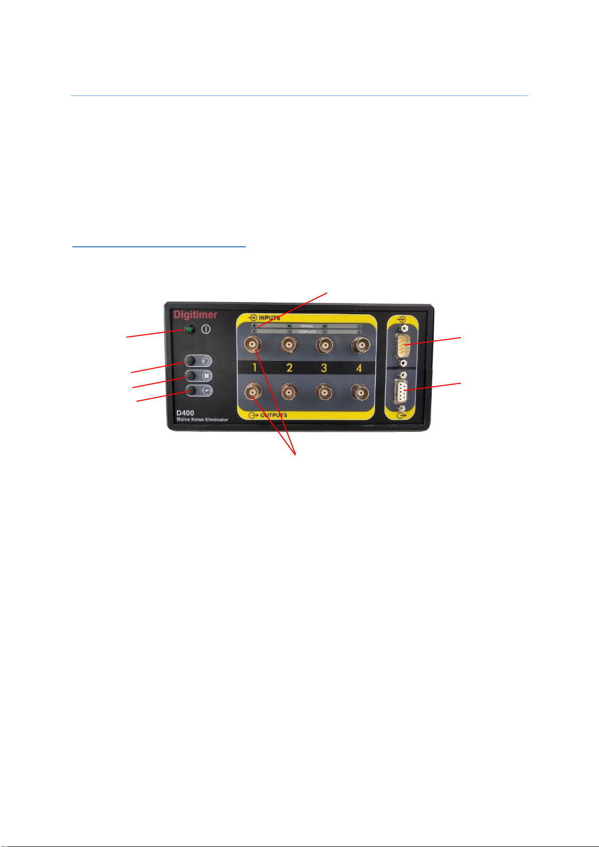
D400 Front Panel Components
Power LED
Once powered on, the D400 will enter a start-up stabilisation phase signified by the front
panel POWER LED flashing green for approximately 40 seconds. This LED will be
permanently lit once the D400 is ready to use.
Signal Input/Output Connectors
The D400 offers the user two alternative methods for signal input and output connection.
For each channel there is a pair of standard BNC connectors designated “Inputs” and
“Outputs”. In addition, two 9-way “D” connectors are available for combining input and/or
output signals via the supplied signal input/output cables.
The operational signal range of the D400 is ±10V and amplifiers or signal conditioners
providing voltages in excess of ±10V are not compatible with the D400.
Channel Status LEDs
Power LED
BNC Signal Inputs/Outputs for Channel 1
Combined
Signal Input
Connector
Combined
Signal Output
Connector
Clear Button
Hold Button
Bypass Button
Digitimer Ltd –D400 Operator’s Manual Version 1.2
14
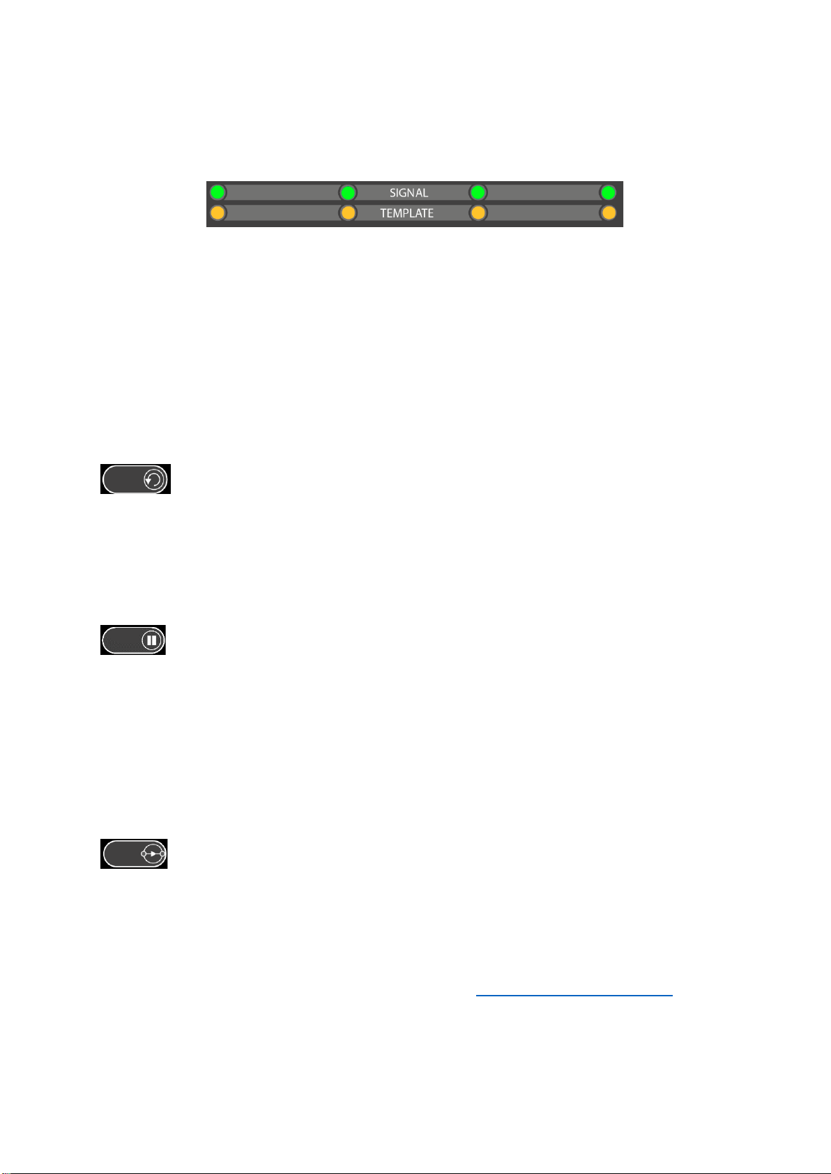
Channel Status LED’s
Above each BNC input socket are two LED’s. When the D400 is actively removing noise from
a signal, the SIGNAL LED is green and the bi-colour TEMPLATE LED is Green or Amber. The
TEMPLATE LED’s change colour or are extinguished when the D400 is in different operating
modes (see below).
Front Panel Controls
The front panel of the D400 has three push buttons. These buttons have the following
functions:-
CLEAR
A single press erases the existing noise template and the D400 begins to construct a new
one. When this button is pressed and the template erased, any previously removed mains
noise present in the signal will re-appear and gradually decrease in amplitude as a new
noise template is constructed.
HOLD
This freezes the noise template so it no longer evolves with changes in the noise level. This
may be useful in situations where the user needs to adjust some recording equipment and
expects to introduce briefly, some additional noise. Pressing HOLD again once the
interruption has taken place, unfreezes the template, causing minimal disruption to the
noise removal process. While the D400 is in the “Hold” mode, the TEMPLATE LED’s are
AMBER.
BYPASS
This allows the user to see what the raw signal passing through the D400 looks like without
any noise cancellation. When the D400 is in “Bypass” mode, the TEMPLATE LED’s are
extinguished.
All three front panel buttons apply their actions globally (i.e. to every channel). For
independent channel control, it is necessary to use the D400 Control Panel Software.

Digitimer Ltd –D400 Operator’s Manual Version 1.2
15
D400 Rear Panel Components
Mains Inlet, Fuse Holder & Power Switch
Accepts standard IEC mains lead (supplied). Operates over 100-120V and 200-240V.
The D440 is fitted with fuses appropriate for the voltage selector setting. These fuses
should only be replaced by qualified personnel.
100-120 V mains T 400 mA L 5 x 20 mm, 250 V
200-240 V mains T 200 mA L 5 x 20 mm, 250 V
Voltage Selector
Check that the voltage selector on the back panel of the instrument is set correctly for your
supply voltage. The factory setting is 230 volts and the alternative is 115 V.
The 230 V setting allows use on supplies from 200 to 240 V.
The 115 V setting allows use on supplies from 100 to 120 V.
Potential Equalisation Connector (PEC)
Earth/Ground reference for unit and bonding point. This is to be used when the
earth/ground conductor in the mains lead cannot be relied upon.
USB Socket
Provides USB connection to host computer running Windows OS. USB connection allows:-
1. Software control of D400 settings via Control Panel.
2. Updates to firmware.
3. Recalibration of the D400.
Mains Inlet,
Fuse Holder &
Power Switch
Potential
Equalisation
Connector (PEC)
USB Socket
Voltage Selector

Digitimer Ltd –D400 Operator’s Manual Version 1.2
16
Installation & Use of the D400
1. Check the D400 and accessories for any sign of damage before proceeding. Please
contact Digitimer if any damage is present.
2. Confirm the rear panel voltage selector is correctly set and mains inlet fuses are of
the appropriate rating for the local power supply voltage.
3. Connect the mains lead to the D400 rear panel mains inlet socket and power the unit
on using the associated On/Off switch. If the D400 Control Panel Software is being
used, double-click on the program shortcut to run it.
4. Once powered on, the D400 will enter a start-up stabilisation phase signified by the
front panel POWER LED flashing green for approximately 40 seconds. This LED will
become permanently lit once the D400 is ready to use.
5. Signal input and output cables may be connected via the BNC sockets or via the “D”
connectors. It is normal for the D400 to be located in the signal pathway after any
amplification or signal conditioning, but immediately before the data acquisition or
visualisation stage.
6. This arrangement ensures the input signals are adequately amplified before noise
subtraction takes place. The D400 accepts and outputs voltages in the range of
±10V.
7. Once signal input and output cables connected, the D400 will start to construct the
noise template and a reduction in mains interference should become apparent
within the observed/acquired signals.
8. The three front panel buttons provide global control of all channel settings, while the
D400 Control Software permits individual channel control.
Amplifier or
Signal
Conditioner
D400 Noise
Eliminator
Data
Acquisition
Interface
Digitimer Ltd –D400 Operator’s Manual Version 1.2
17
D400 Control Panel Software
The D400 is a standalone device and does not need any software, however, our Control
Panel replicates the three physical front panel buttons on the D400 and also provides the
following additional features:-
Individual control of the Clear, Hold and Bypass functions for each channel.
Ability to toggle the input signal on and off, allowing the noise template to be
visualised in isolation from the signal of interest.
Software Installation
The D400 Control Panel software is available from the Digitimer website. The software is
intended for use and is compatible with 32bit or 64bit Microsoft Windows 10 operating
systems. Compatibility with earlier versions of Windows is not guaranteed.
1. Download the software installer and if necessary copy the file to a USB stick and
insert into a USB port on the host PC.
2. Browse to the D400 Control Panel software installation file.
3. Double-click on the installation file and follow the installation instructions.
4. Following installation, a D400 shortcut will be placed on the Windows desktop.
5. Connect the D400 to the host PC using supplied USB cable and power it on.
6. Double-click on the D400 desktop shortcut to run the D400 Control Panel Software.
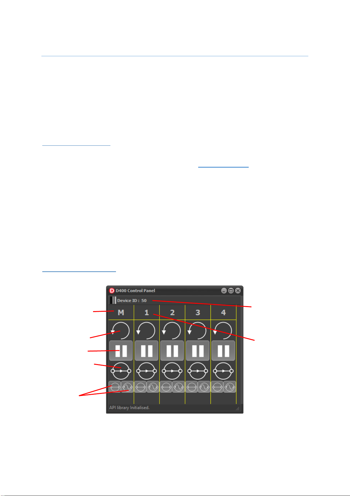
Software GUI Controls
Master Channel
Label
Input/Template
Controls
Clear
Hold
Bypass
D400
Serial Number
Channel 1 Label

Digitimer Ltd –D400 Operator’s Manual Version 1.2
18
The software controls of the D400 are laid out in a grid, with Master Control (M) on the left
and individual channel control labelled 1 and 2 (D400-2) or 1 to 4 (D400-4) in the additional
columns of the grid. Below the channel labels are three large “Clear”, “Hold” and “Bypass”
icons. Clicking on these icons replicates the actions of the hardware buttons, making
settings changes that are global (Master channel) or on a per channel basis.
Below the “Clear”, “Hold”and “Bypass”controls are a pair of smaller icons, associated with
the Bypass feature, that allow the user to toggle the input signals (left icon) and template
subtraction processes (right icon) on or off.
The table below summarises how these two controls influence the behaviour of the D400
and which signals are passed to the outputs.
Icon Status
Front Panel LED Status
Description of D400 Mode
Signal: Green
Template: Green or Amber*
Normal Operating Mode (Bypass OFF)
The input signal is passing through the
D400 to the output and template
subtraction process is active i.e. normal
noise subtracting state.
Signal: Green
Template: Extinguished
Bypass Mode ON
The input signal is passing through the
D400 to the output, but the template
subtraction process is inactive i.e. the input
signal = output signal and noise is not being
actively removed.
Signal: Extinguished
Template: Green or Amber*
The input signal is not passing through the
D400, but the template subtraction process
is still active. The output signal is the
inverted noise template and does not
include the input signal.
Signal: Extinguished
Template: Extinguished
The input signal is not passing through the
D400 and the template subtraction process
is inactive. The output signal reflects the
output noise from the D400.
* Template LEDs are Amber if Hold is active
Third Party Software Control
The D400 Control Panel software incorporates a simple advanced programmer’s interface
(API), which is available for users who wish to control the D400 via their own or third party
software, rather than use our own GUI. If you are interested in using the API, please contact
us, providing details of the software you intend to use and what programming or scripting
languages you typically employ.

Digitimer Ltd –D400 Operator’s Manual Version 1.2
19
References
As the D400 is a new product we do not have any publications that cite its use, however, if
you publish research which has used the D400, please cite the Digitimer D400-2 or D400-4 in
your methods section to help other researchers e.g. D400-2 Mains Noise Eliminator
(Digitimer Ltd., Welwyn Garden City, UK).
Digitimer would appreciate a copy of any relevant publications and could add details to this
section of the manual.

Digitimer Ltd –D400 Operator’s Manual Version 1.2
20
Digitimer Limited
37 Hydeway
Welwyn Garden City
Hertfordshire
AL7 3BE
UK
Tel: +44 (0)1707 328347
Fax: +44 (0)1707 373153
E-mail:
Website: www.digitimer.com
File Reference: N:\Docs\Company\Manuals\D400\D400_Manual_v1.2.docx
Last updated: 04/12/20
This manual suits for next models
2
Table of contents
Popular Recording Equipment manuals by other brands

AudioSource
AudioSource AE4SW owner's manual

TubeDepot
TubeDepot Tweed 5E3+ Assembly manual

Lutron Electronics
Lutron Electronics PAV6M-120 installation guide

PRESONUS
PRESONUS AudioBox Stereo quick start guide

DK Digital
DK Digital CDB-650 owner's manual

Murphy
Murphy CANdrive Module CDV100F Installation and operation manual

DSC
DSC gs3055-i cf installation manual

Autek Research
Autek Research QF-1A user manual

Mitsubishi Electric
Mitsubishi Electric DX-TL4509E series user manual

M-Audio
M-Audio USB OMNISTUDIO quick start guide

Dension
Dension Smartlink MHL-9203-1 install guide

Electro-Harmonix
Electro-Harmonix 1440 quick start guide


