Digitron FM25 User manual

FM25
WIRELESS DIGITAL
THERMOMETER
FM25
WIRELESS DIGITAL
THERMOMETER
FM25
WIRELESS DIGITAL
THERMOMETER
TEMPERATURE ALARMS- PROGRAMMING CUSTOMISED
PRESETS
To customise the preset alarm temperatures, press and hold the
desired alarm button (sensor #1 or sensor #2). You are now in the
MAX temp. alarm set mode and may adjust the maximum
temperature by using the “+” or “-“ buttons. Press the alarm button
again to confirm your setting for the minimum alarm temperature and
to exit the entire alarm preset temperature mode. Repeat this
process to set the other minimum and maximum alarm temperatures
for the other remote sensor.
TROUBLESHOOTING
If batteries are installed the main unit will display “- - ” until it
acquires the wireless signals from the remote sensor units. If the
unit still displays “- - ” the remote units' batteries may be dead or the
main and remote units cannot synchronize wireless signals. Try
moving the main unit to a different location.
ERROR DISPLAY
If the unit displays “-E-” then this is an error condition and the
receiver has not received a signal from either sensor #1 in the last 4
hours or from sensor #2 in the last 3 hours.
To remove the “E” from the display it is necessary to reset both the
receiver and transmitters at the same time. This can be done by
either removing batteries of each unit or using a small paper clip or
pin, and poke it through the reset hole located on the rear of the deg
C/F switch. The unit will display - - - on both channels then start
reading temperature after a minute or so.
If the product doesn't display the temperature then it will be
necessary to move the receiver closer to the sensors and/or replace
the batteries.
Please note that the maximum recommended range is 15metres
due to the wall thickness of refrigerators/freezers.
LOW BATTERY INDICATOR
A low battery indicator is shown in the display window for the remote
sensors. When the low battery indicator displays, replace the
batteries with fresh ones. Be sure to never mix old and new
batteries, and never mix battery types such as alkaline and lithium
together.
CHANGING BATTERIES
If it is necessary to change the batteries of the sensors and if there
are two units in close proximity, then batteries will need to be
changed within eight minutes to avoid the base station picking up
readings from alternative sensors.
IP RATING
This product has an IP54 rating. Note: The product cannot be
submersed in water or any other liquid.
Temperature Measurement Range:
MAIN UNIT: - 30ºC to + 40ºC / -22ºF to 104ºF
NOTE: If the remote sensor units are measuring temperatures
above the temperature range the main unit will display “-H-“. If the
remote sensor units are measuring temperatures below the
temperature range, the main unit will display “-L-“.
OPERATING
INSTRUCTIONS
OPERATING
INSTRUCTIONS
OPERATING
INSTRUCTIONS
14511 rev.2
14511 rev.2
14511 rev.2

BATTERIES
It is recommended that AA lithium batteries are used for the low
temperature operation of sensors (freezers etc).
INSTALLING BATTERIES
For the two remote sensor units, remove the battery compartment
cover by sliding it downwards. Insert 2 “AA” alkaline/lithium
batteries. Lithium batteries function at lower temperatures better
than alkaline batteries.
PLACEMENT
The remote units should be fixed onto the refrigerator/freezer at this
stage. Each remote unit is equipped with a spring-action clip for
securing inside the refrigerator or freezer. The clip is designed with
rubber grips to securely hold the remote unit to the edge of glass or
wire shelf commonly found in modern refrigerators.
Alternatively, the included detachable suction cup may be used to
secure the remote sensor to the interior surface Ref #1. A remote
unit kept in a freezing temperature should be secured using the
integrated spring-clip Ref #2.
The main unit may be mounted directly to the refrigerator surface
utilizing the magnetic back of the unit. The main unit may also be
placed on a table or other flat surface using the integrated fold-out
stand on the back of the unit.
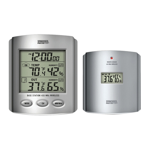
THE MAIN DISPLAY
Each sensor's temperature is represented on the main display in
three ways. The largest numbers displayed represent the current
temperature of each remote sensor. The two smaller numbers to
the right in each sensor's display window represent the minimum
and maximum-recorded temperatures. The recorded MIN/MAX
numbers can be cleared by pushing the “CLR” button. You may also
choose between Fahrenheit or Celsius temperature display mode
using the “C/F Select” switch on the back of the main unit.
TEMPERATURE ALARMS
The main unit is equipped with an audible temperature alarm for
each unit. Press the alarm button for the corresponding remote
sensor to turn the alarm function on or off. The ALARM icon on the
main display will appear if the alarm function is on. If the alarm icon
is not displayed, the alarm WILL NOT SOUND.
If the temperatures for each sensor fall below the minimum preset or
rise above the maximum preset for more than 15 minutes, the alarm
will sound. This is to prevent “ False alarms” from sounding because
the door was opened to load or unload items from a refrigerator or
freezer. The sensors are supplied with the following defrost preset
alarm temperatures:
Sensor #1 (Refrigerator): minimum is 0ºC/33F, maximum is 4ºC/
40F.
Sensor #2 (Freezer): minimum is -30ºC/22F, maximum is -18ºC/0F.
You may customise the alarm to sound at your desired temperatures
for each unit. See page 5 for instructions on programming the alarm
preset.
Other Digitron Thermometer manuals
