2
Operating instructions
Hinge safety switch TESK
EN
1.6 Warning about misuse
In case of improper use or manipulation of the safety switch-
gear, personal hazards or damages to machinery or plant
components cannot be excluded. The relevant requirements
of the standard EN 14119 must be observed.
1.7 Exclusion of liability
We shall accept no liability for damages and malfunctions resulting from
defective mounting or failure to comply with this operating instructions
manual. The manufacturer shall accept no liability for damages resul-
ting from the use of unauthorised spare parts or accessories.
For safety reasons, invasive work on the device as well as arbitrary re-
pairs, conversions and modifications to the device are strictly forbidden;
the manufacturer shall accept no liability for damages resulting from
such invasive work, arbitrary repairs, conversions and/or modifications
to the device.
2. Product description
2.1 Ordering code
This operating instructions manual applies to the following types:
TESK-
➀
-
➁
-
➂
-
➃
-
➄
No. Option Description
➀
S Standard hinge
L Long hinge half
➁
A preset for front assembly
I preset for inside assembly
U freely adjustable switching angle
➂
22 2 NO contacts / 2 NC contacts
12 1 NO contacts / 2 NC contacts
13 1 NO contacts / 3 NC contacts
02 2 NC contacts
11 1 NO contacts / 1 NC contacts
➃
L1 Cable downwards
L2 Cable upwards
ST1 Connector plug bottom
ST2 Connector plug top
➄
3M Cable length 3 m (only L1 / L2)
5M Cable length 5 m (only L1 / L2)
10M Cable length 10 m (only L1 / L2)
20M Cable length 20 m (only L1 / L2)
30M Cable length 30 m (only L1 / L2)
2.2 Special versions
For special versions, which are not listed in the order code below 2.1,
these specifications apply accordingly, provided that they correspond to
the standard version.
2.3 Destination and use
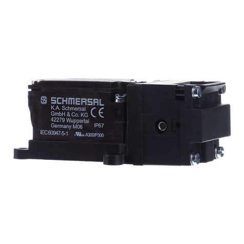
The TESK hinge safety switch has been designed to prevent, in con-
junction with the control part of a machine, movable safety guards from
being opened before hazardous conditions have been eliminated. They
are also suitable for fitting on profile sections and existing equipment.
Hinge safety switches can only be used for applications, in
which the hazardous condition is terminated without delay
(e.g. run-on movements) when the safety guard is opened.
The user must evaluate and design the safety chain in
accordance with the relevant standards and on the required
safety level.
The entire concept of the control system, in which the safety
component is integrated, must be validated to the relevant
standards.
2.4 Technical data
Standards: IEC 60947-5-1; EN ISO 13849-1;
EN 14119; BG-GS-ET-15
Enclosure: Zinc diecast, enclosure cover
self-extinguishing thermoplastic
Hinge pin: Galvanised steel / Steel C45
Attachment: 4 x M6 screws DIN 7984 or ISO 4762
with TESK-L… 6 screws
Tightening torque 4.3 Nm
Contact material: Silver, gold-plated
Contact type: Change-over contact with double break Zb
Switching system: IEC 60947-5-1; Slow action,
A
positive break NC contacts
termination: connector plug M12 or cable
Connector plug: M12, 5- or 8-pin, A-coded
Connection cable: Y-UL 2464 / 9 x AWG 22 / 9 x 0.34 mm²
Y-UL 2464 / 5 x AWG 22 / 5 x 0.34 mm²
Temperature resistance of the cable:
- at rest: -25°C ... +80°C
- in motion: -5°C ... +80°C
Switching angle: 3° adjusted from zero point
Forced opening angle: 10° adjusted from zero point
Positive break torque: 0.35 Nm
Max. swivel angle: 270°
Actuating speed: max. 180°/0.3 s
Bounce duration: in accordance with actuating speed
Switchover time: in accordance with actuating speed
Actuating frequency: max. 120 operations/h
Mechanical life: > 1 million operations
Note - mechanical service life:
Switching cycles matched to:
Door size: 1 m x 1 m
Door weight: 20 kg
using an
additional hinge according to Section 7.3
Resistance to shock: 30 g / 11 ms
Resistance to vibration: 10 … 150 Hz, amplitude 0.35 mm
Ambient temperature:
Storage and transport temperature: …+85 °C
Protection class: IP65 to IEC/EN 60529
Protection class: I
- Plug type: III
Utilisation category: AC-15, DC-13
Ie/Ue:
- Cable design: 2 A / 230 VAC
1 A / 24 VDC
- Plug design: 1 A / 24 VDC
Ui:
- Cable design: 300 V
- Plug design, M12 8-pin: 30 V (PELV according to DIN EN 60204-1)
- Plug design, M12 5-pin: 60 V
Uimp:
- Cable design: 2.5 kV
- Plug design, M12 8-pin: 0.5 kV
- Plug design, M12 5-pin: 0.8 kV
Ithe:2.5 A
Uemax: 230 V Cable version
30 V plug 8 - pin
60 V plug 5 - pin
Max. fuse rating: 2 A gG D-fuse
Switching of low voltages: 1 mA / 3 VDC
Mechanical breaking load (see fig. 1):
- F1: 5,000 N
- F2: 5,000 N
See Section 7.3 Load details

