B&K 600 User manual

DYNA-JET
&
mF #INSTRUCTION MANUAL MODEL
600
—
TUBE TESTER
jHiijim
DIVISION OF DYNASCAN CORPORATION
1801 W. Belle Raine Ave. Chicago, Illinois 60613

OPERATING INSTRUCTIONS
FOR
Model 600
DYNA-JET
TUBE TESTER
B& K DIVISION OF DYNASCAN CORP.
1801 West Belle Plaine Avenue
Chicago, lUinois 60613
MODEL 600 TUBE TESTER
What It Will Do
1. The Dyna Jet Model 606 Tube Tester will test all of the commonly
used tubes in general use in radio and television sets.
2. In addition it will test many voltage regulator tubes, thyratron tubes,
industrial types of tubes and many of the European types found in
modern hi fi equipment,
3. Each tube is automatically checked for shorts and leakage to approxi-
mately one megohm. These tests are made from each element to every
other element so that all possible combinations of shorts can be detected.
4. Grid Emission, Gas, Grid Contamination, or obscure Grid to Cathode
leakage are all disclosed by an exceptionally sensitive grid current
check. This test will reveal as little as 2to 3 microamperes of current
in the grid circuit and can be adjusted for asensitivity of over
100 megohms.
5. Each section of amulti section tube is checked separately,
6. Each tube is checked for quality in atest circuit that determines the
full capability of cathode emission under current loads simulating
actual operating conditions.
Testing Tubes for Shorts
The Shorts check is automatically made when a tube is placed in the
proper socket.
The Shorts check uses aneon lamp as the indicator. Shorts or leakages to
approximately 1megohm will cause this lamp to glow. This Shorts indicator
is located just below the meter. See Fig. 1,
Acheck on grid to cathode leakage is made as soon as the tube is plugged
into the socket. The Shorts check between all other elements is made by
rotating the switch “C” through its positions, observing the Shorts light as
the switch is rotated.
Testing Tubes for Quality
The test for the quality of atube is acomprehensive cathode emission test.
It is important to test the tube under aload condition which will insure that a
tube passing this teat will have adequate emission to properly operate in
acircuit
TESTING TUBES FOR GRID EMISSION AND GAS
The Grid Emission and Gas Test is an invaluable aid in TV servicing be-
cause it quickly picks out those tubes which can c^use trouble in a.g.C», sync,
IT. amplifier* and R,F. tuner circuits.
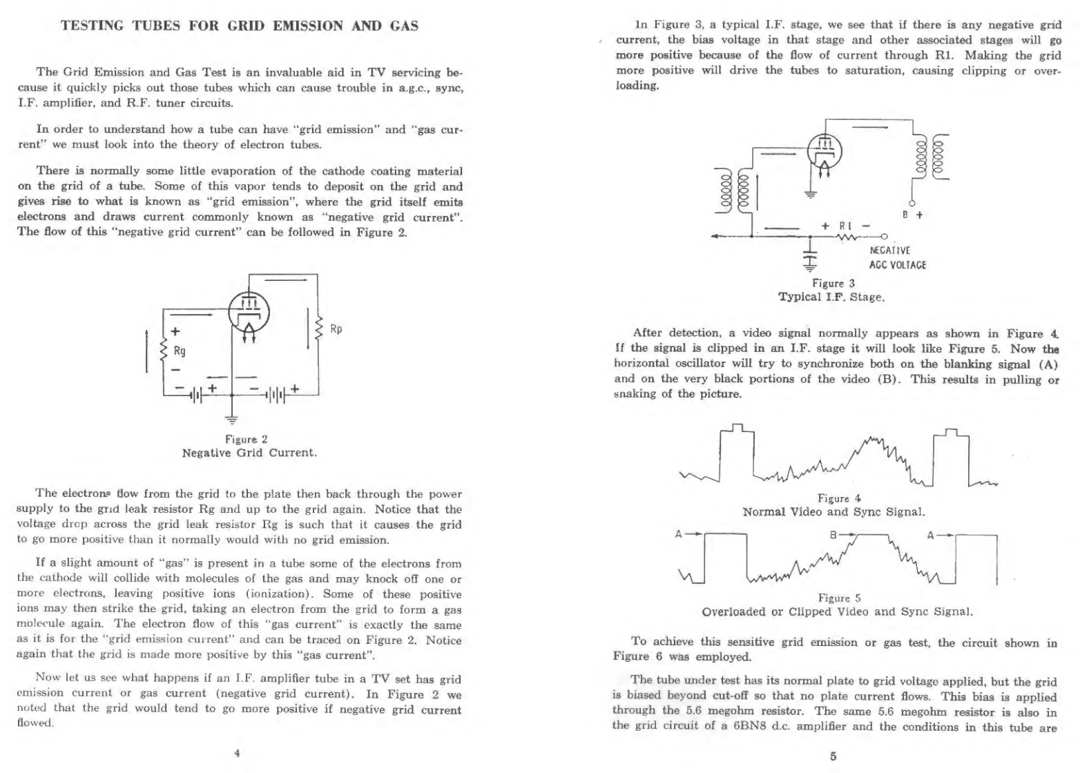
In order to understand how atube can have “grid emission" and “gas cur-
rent" we must look into the theory of electron tubes.
There is normally some little evaporation of the cathcnie coating material
on the grid of atube. Some of this vapor tends to deposit on the grid and
gives rise to what is known as “grid emission”* where the grid itself emits
electrons and draws current commonly known as “negative grid current”.
The flow of this “negative grid current” can be followed in Figure 2.
Figure 2
Negative Grid Current.
The electrons fiow from the grid to the plate then back through the power
supply to the grid leak resistor Rg and up to the grid again. Notice that the
voltage drop across the grid leak resistor Hg is such that it causes the grid
to go more positive than it normally would with no grid emission.
If aslight amount of “gas” is present in atube some of the electrons from
the cathode will collide with molecules of the gas and may knock of! one or
more electrons, leaving positive ions (ionization). Some of these positive
ions may then strike the grid, taking an electron from the grid to form agaa
molecule again. The electron flow of this “gas current” is exactly the same
as it is for the “grid emission current" and can be traced on Figure 2, Notice
again that the grid is made more positive by this “gas current”.
Now let us see what happens if an LF. amplifier tube in aTV set has grid
emission current or gas current (negative grid current). In Figure 2we
nottxl that the grid would tend to go more positive if negative grid current
flowed.
4
In Figure 3, atypical LF, stage, we see that if there is any negative grid
*current, the bias voltage in that stage and other associated stages will go
more positive because of the flow of current through Rl. Making the grid
more positive will drive the tubes to saturation, causing clipping or over-
loading.
5ACC VOLTAGE
Figure 3
Typical I.F, Stage.
After detection, avideo signal normally appears as shown in Figure A
If the signal is clipped in an I,F, stage it will look like Figure 5, Now tha
horizontal oscillator will try to synchronize both on the blanking signal (A)
and on the very black portions of the video (B). This results in pulling or
snaking of the picture.
Figure 4
Normal Video and Sync Signal,
Figure 5
Overloaded or Clipped Video and Sync Signal.
To achieve this sensitive grid emission or gas test, the circuit shown in
Figure 6was employed.
The tube under test has its normal plate to grid voltage applied, but the grid
is biased beyond cut-off so that no plate current flows. This bias is applied
through the 5.6 megohm resistor. The same 5.6 megohm resistor is also in
the grid circuit of a6BNS d,c, amplifier and the conditions in this tube are
5

fiuch that it, too? is biased just beyond cut-off. Under these conditions, no
plate current flows in the 6BN8 and no reading is obtained on the meter in
its plate circuit.
However, if the tube under test is gaseous, or its grid is contaminate<i with
some of the cathode coating, then current will flow from grid to plate and
through the 5.6 meg resistor back to the grid again. This will produce aposi*
live voltage drop across the 5,6 meg resistor, lifting the cut-off bias on the
6BN8 and producing ameter deflection. Upon seeing this deflection, the
technician immediately knows that the test tube is defective and areplacement
is indicated.
HOW TO OPERATE THE DYNA JET MODEL 600 TUBE TESTER
Simplified Instructions
1. Look up tube in chart
2. Set Heater to voltage indicated in Heater column of chart.
3. Set “A**, "B” and “C" controls to positions indicated on chart.
4. Insert tube into proper socket as indicated on chart.
5. Allow tube to warm up and observe Shorts indicator. If Shorts light
glows, reject tube.
6. Depress Grid Emission button. Any deflection of the meter pointer
into the “Grid Emission-Reject" area of the scale is cause for reject
of the tube.
7. Depress Quality button. Tube will read on the Good-Bad scale of
the meter.
8. To test for all other shorts rotate Switch through each of its
positions and observe Shorts lamp. (The Shorts lamp may glow
instantaneously while rotating switch “C” through ita position. This
is due to acapacitor discharge and is to be ignored.)
TEST PROCEDURE
I
The Model 606 Tube Tester is designed for use at 105^125 volts, 50*60 cycle
A.C. only. The instrument is turned on and ready for use merely by inserting
the line cord into an A.C, socket. The first step in the testing of atube is to
look up this tube in the chart contained in the cover of the instrument. Let us
take atypical example such as a6AU6. Fig. 7shows atypical listing for this
type. The heater voltage for this tube type is 6, as shown, and the heater
switch must therefore be set to the 6voH position. This will then apply the
correct heater voltage to the tube under test.
1^" __ »wter "A" ^^Socket Ne.
6AU6 633 S11
Figure 7.
If the tube in question had a17 volt heater, the heater switch will be
rotat^ to the 15-20 position. Any tube with a heater voltage between 15-20
volts is tested with the heater switch in this position,
CAUTION! THE HEATER SWITCH MUST BE SET TO THE COR-
RECT FILAMENT VOLTAGE BEFORE INSERTING THE TUBE IN
THE SOCKET. FAILURE TO OBSERVE THIS PRECAUTION MAY
RESULT IN BURNING OUT THE FILAMENT OF THE TUBE.
'“set to 33, the "B” switch placed in position 6, and the
"C switch in position 1, The tube is now inserted into socket No. 1, as shown
mthe last column of the type UsUng in Fig. 7. The tube is automatically tested
for grid to cathode shorts and leakage as soon as the tube is inserted into
the socket
To test for grid emission, depress the Grid Emission button. Any deflection
of the meter pointer into the “grid emission*reject“ area of the meter scale
indicates adefective tube. This tube should be discarded. If the tube passes
the Grid Emission test, we then proceed to the Quality test.
The tube is tested for Quality by depressing the Quality button and observing
the Good-Bad reading on the meter scale. Afew tube types do not normally
register ameter reading mto the “Good” area because of our exceptionally
critical Quah^ test. For these types the chart indicates the minimum
numencal reading that this tube must have to be acceptable.
The tube can be tested for shorts or leakage between any of the other
elements by rotating switch “C” through each of its positions. If the Shorts
indicator neon lamp glows in any of the switch positions of switch “C” the
tube should be rejected. (As the switch is rotated from one position to the next
shorts indicator may instantaneously glow due to acapacitor discharge'
Inis 13 to be ignored.)
C3U rJT ^1^TJiuitJOLiun lor agiven element,
therefore the Short mdicator lamp may normally glow in certain positions of
Switch C.even if fhexe is no short in the tube. The chart will indicate where
^normal short indication will occur. These tubes should not be rejected
for these normal shorts. ^
This completes the test on the tube.
67
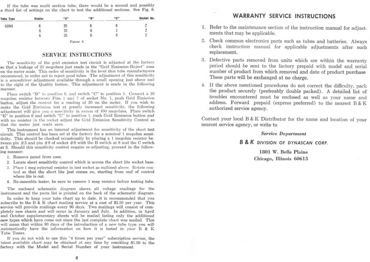
If the tube was multi section tube, there would be asecond and possibly
athird list of settings on the chart to test the additional sections. See Fig* 8. WARRANTY SERVICE INSTRUCTIONS
Tata Type Heater ^c;; Ho,
6BN8 6 35 6S2
635 612
635 66 2
Fipure 0.
SERVICE INSTRUCTIONS
The sensitivity of the grid emission test circuit is adjusted at the factory
so that aleakage of 25 megohms just reads in the '"Grid Emission-Reject” area
on the meter scale. This order of sensitivity is the level that tube manufacturers
recommend, in order not to reject good tubes. The adjustment of this sensitivity
is ascrewdriver adjustment available through asmall opening just above and
to the right of the Quality button. This adjustment is made in the following
manner.
Place switch “B” to position 6, and switch to position 1. Connect a 20
megohm resistor between Pins 1and 7of socket No* 1, push Grid Emission
button, adjust the control for areading of 20 on the meter. If you wish to
make the Grid Emission test at greatly increased sensitivity, the following
adjustment will give you asensitivity in excess of 100 megohms. Place switch
“B” in position 6and switch "C” to position 1, push Grid Emission button and
with no resistor in the socket adjust the Grid Emission Sensitivity Control so
that the meter just reads zero.
This instrument has an internal adjustment for sensitivity of the short test
circuit. This control has been set at the factory for anominal 1megohm sensi*
tivity. This should be checked occasionally by placing a1megohm resistor be-
tween pin #3 and pin #8 of socket #8 with the Bswitch at 6and the Cswitch
at 3* Should this sensitivity control require re- adjusting* proceed in the follow-
ing maimer:
1. Remove panel from case,
2. Locate short sensitivity control which is across the short lite socket base*
3. Place Imeg external resistor in test socket as outlined above. Rotate con-
trol so that the short lite just comes on, starting from end of control
where lite is out*
4. Re-assemble tester, be sure to remove 1meg resistor before testing tube.
The enclosed schematic diagram shows all voltage readings for the
instrument and the parts list is printed on the back of the schematic diagram*
In order to keep your tube chart up to date* it is recommended that you
subscribe to the B&Kchart mailing service at acost of $2.50 per year. This
service will provide mailings every 90 days* Two mailings will consist of com-
pletely new charts and will occur in January and July. In addition, in April
and October supplementary sheets will be mailed listing only the additional
new types which have come out since the last complete chart was maOed. This
will mean that within 90 days of the introduction of anew tube type you will
automatically have the information on bow it is tested in your B & K
Tube Tester*
If you do not wish to use this “4 times per year” subscription service* the
latest available chart may be obtained at any time by remitting $1.50 to the
factory with the Model and Serial Number of your instrument.
1. Refer to the maintenance section of the instruction manual for adjust-
ments that may be applicable.
2. Check common electronics parts such as tubes and batteries. Always
check instruction manual for applicable adjustments after such
replacement.
3. Defective parts removed from units which are within the warranty
period should be sent to the factory prepaid with model and serial
number of product from which removed and date of product purchase
These parts will be exchanged at no charge.
4. If the above mentioned procedures do not correct the difficulty, pack
the product securely (preferably double packed). Adetailed list of
troubles encountered must be enclosed as well as your name and
address. Forward prepaid (express preferred) to the nearest B&K
authorized service agency.
Contact your local B&KDistributor for the name and location of your
nearest service agency, or write to
Service Department
B&KD/WSION OF DYNASCAN COftP.
1801 W. Belle Plaine
Chicago, Illinois 60613
8
WARRANTY
^"B &Kwarrant that each product manvfActured by it will be (tee from deEecta mmaterial and
workmatiahip under ngrmal usage and service lor aperiod ot ninety days after its purchase new
from an authorized B&. Kdistributor. Our obligaLiou under this warranty ia limited to repairing,
ot replacing any product -or component which we aie satisfied does not oonfoma with the fore-
going warranty and which ia returned to out lactory or our authorized service contractor, transpor-
talion prepaid, and we shall not otherwise be liable for any damag&i, coasequential or otherwise.
The foregoing warranty is exclusive and in lieu of all other t^xirranties (including any umrranfy of
merchantability)twhether express or implied. Such warranty shall not apply to any product or
component {i> repaired or altered by anyone other than E & Kor its authorized service contractor
(except normal tube repiaccmont) without B&K's prior written approval; (ii) tampered with or
altered in any way or subjected to misuse, negligence or accident: (iii> which has the serial micaher
altered, defaced or removed; or (iv) which has b«n improperly connected, installed or adjusted
otherwise than in accordance with B & K"s inatructions. Btk Kreserves tbs right to discontinue
any model at any time or change specifications or design without notice end without incurring any
obligation. The warranty shaU be toid and there shall be no warranty of any product or com-
ponent if aB^Kwarranty registration card is not properly completed and postmarked to the
BSKfactory within five days after the purchase of the product new from an authorized
Bdi Kdistributor."
B&KmVISION OF DYNASCAN CORPORATION
leoi wBELLE PLAlNE AVE •CHICAGO. ILL. «0613
4SO DS7 e-OOl la-ae rupress Copyright ©1961
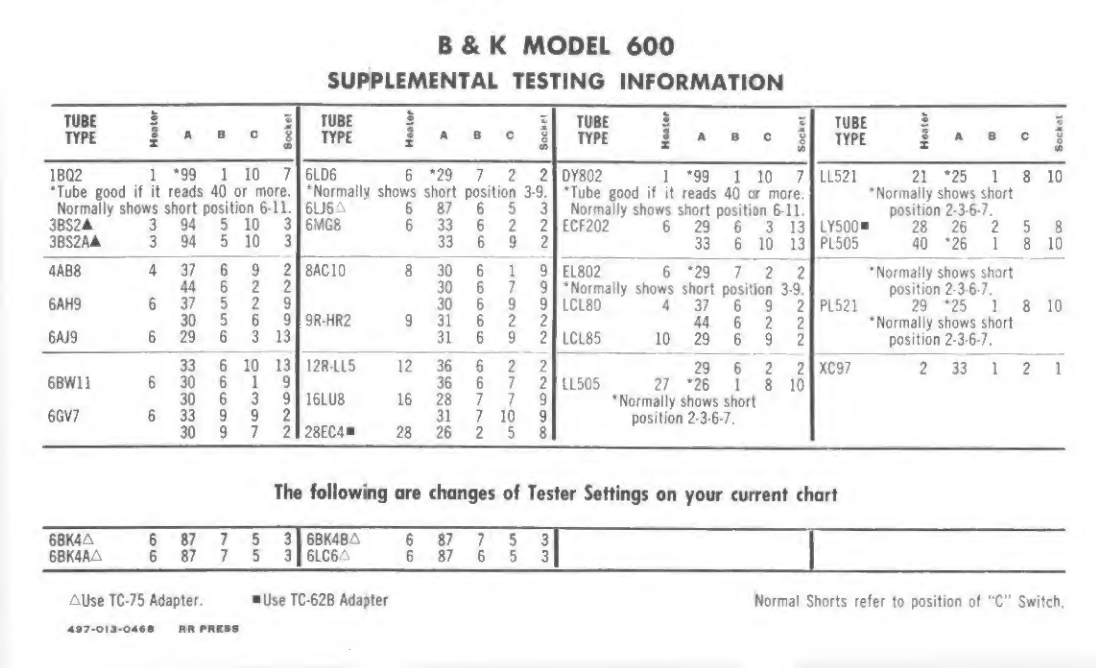
B&KMODEL 600
SUPPLEMENTAL TESTtNG INFORMATION
mM SMUS 2m0moV
IH S
XAB 0 i3
XA B c 1njl 1*BC1Kjil Sab
Xcu
1BQ2 1*99 110 7 |6LD6 e*29 72 2 1DY802 1*99 110 LL521 21 *25 1T10
'Tube good if it reads 40 or more. ‘Normally shows short position 3-9, ‘Tube good if it reads 40 or more. Normally shows short
Normally shows short position 6-1 1. 6U6 A6 87 653Normally shows short position 6-lL position 2-3-6-7,
3BS2A 394 510 36MQ8 s33 622ECF202 629 6 3 13 LY500" 28 26 258
3BS2AA 394 510 333 6 9 233 610 13 PL505 40 *26 1810
4AB8 437 6 9 Z BAG 10 3 30 619EL802 6*29 722i ^Normally shows short
44 62 1 30 679‘Normally shows short posidon 3-9. position 2-3*6 7.
6AH9 637 52 9 30 699LCL80 437 692PL521 29 *25 18 10
30 5699R-BR2 9 31 6 2244 6 2 2Normally shows short
6AJ9 629 6 3 13 31 6 9 2LCLS5 10 29 6 9 2position 2-3 6-7,
33 610 13 12R-LL5 12 36 622 29 622XC97 2 33 121
6BW1! 630 619' 36 6721L505 27 *26 1310
30 0391GLU8 16 23 779^Normally shows short
6GV7 633 992 31 7 10 9 position 2-3- 6-7.
30 97 2 28EC4W 28 26 258
The following are changes of Tester Settings on your current chart
6BK4A 687 7536BK4BA G87 753
6BK4AA 687 7536LC6A E87 653
Alise TC-75 Adapter* Use TC‘62B Adapter Normal Shorts refer to position of "C" Switch.
4»7-ora-o4«a ft It PltlSS


Table of contents
Other B&K Test Equipment manuals


Popular Test Equipment manuals by other brands


Tonghui Electronics
Tonghui Electronics TH9110 Operation manual

CharlesWater
CharlesWater 99090 Operation and maintenance

Tektronix
Tektronix A6312 instructions

inTest
inTest Temptronic ThermoStream TP04300 Series Service manual

Höcherl & Hackl
Höcherl & Hackl PMLA Series user manual

Dongguan Xin Bao Instrument
Dongguan Xin Bao Instrument XB-OTS-106 Operation manual


