ELMED Isotest II RT User manual

Operating Manual Isotest II T / II RT Page 1
CONTENTS
1 Introduction ..................................................................................................2
1.1 Safety Instructions...............................................................................2
1.2 General Characteristics .......................................................................4
1.3 First Steps............................................................................................5
1.3.1 Setting the Test High Voltage............................................................6
1.3.2 Setting the Display Sensitivity............................................................7
2Acoustic Signals During the Test Procedure................................................8
2.1 Flaw (Pore)..........................................................................................8
2.2 Exhaustive Discharge Protection of the Battery...................................8
2.3 Lack of Earth Connection.....................................................................8
2.4 Load Exerted by the Test Specimen....................................................9
3Maintenance.................................................................................................10
AAnnex...........................................................................................................11
A.1 Technical Data.....................................................................................11
A.1.1 Power Supply.....................................................................................11
A.1.2 Test Voltage.......................................................................................11
A.1.3 Dimensions and Weights...................................................................11
BChecklist.......................................................................................................12
1 Testing the Readiness for Operation........................................................12
1.1 Battery (Varta 5M6 6 V/6 Ah or Sonnenschein 6 V / 6.5 Ah)...........12
1.2 Meaning of the Acoustic Signals......................................................12
2 Test Voltage.............................................................................................14
2.1 Checking for High Voltage at the Test Electrode.............................14
2.2 Is the Test Voltage Level Correctly Set?..........................................14
2.3 Is the Test Voltage Monitored with a Sphere Gap?.........................14
3 Earthing....................................................................................................14
3.1 Methods of Earthing ........................................................................14
4 Test Procedure ........................................................................................18
4.1 Is an Automatic Controller Installed in the Tester?..........................18
4.2 Are the Test Electrodes in Order?...................................................18
4.3 Special Tests...................................................................................19
CTable for Intermediate Values of the Test Voltage .......................................20
Isotest II RT-F - Special Model
In this special model, the test voltage is set with a micro-drive. This gives a higher
degree of precision, particularly with low test voltages. For technical reasons, the
test voltage is limited to 25 kV.
In this manual, the designation II RT(-F) stands for tester model II RT as well as for
model II RT-F. Type II RT-F is mentioned specifically only where there are devia-
tions between the two models.

Page 2Operating Manual Isotest II T / II RT
1Introduction
1.1 Safety Instructions
The following instructions are given for your safety.
Due to the fact that operation of the ELMED Isotest is so simple, there is a great
temptation to use the tester without reading the operating manual.
!Nevertheless, for your own safety,
take a few minutes to read the manual
before switching on the tester for the first time. !
!Important note for wearers of a
heart pacemaker
For safety reasons, wearers of a heart pacemaker should not operate
an insulation tester and in particular should avoid contact with the test
electrode, the tested pipe and/or the earth cables, irrespective of the type
of heart pacemaker or insulation tester.
The influence of insulation testers on heart pacemakers has not yet been
scientifically investigated.
!

Operating Manual Isotest II T / II RT Page 3
CAUTION !!
Before fitting or changing the test electrode
•Turn off the tester at the main switch
•The safety switch on the handle must not be pressed.
Before putting the tester into operation, always check the following parts:
•The handle for dirt and moisture
•The proper function of the safety switch
•The high-voltage cable for mechanical damage
On no account may the plugs on the battery leads be short-circuited in order to
avoid
•The risk of fire, and
•Destroying the battery
Even a brief short-circuit can result in the destruction of the battery and is not a
suitable method for checking the state of battery charge.
CAUTION !!
Should any work be necessary on the tester, this should only be carried out by
trained specialist personnel.
Particular care is necessary as opening the tester exposes the user to voltages which
are considerably higher than the supply voltage.

Page 4Operating Manual Isotest II T / II RT
1.2 General Characteristics
Both tester series II T with a fixed test high voltage and series II RT(-F) testers with
infinitely variable test high voltage up to 35 kV are characterised by the following
features:
•Efficient, safe and reliable testing of coatings or sheathings of a wide range of
different types and thicknesses.
•The possibility of testing all non-conductive and barely conductive materials for
leaks and pores.
•The extremely short high-voltage pulses ensure that even the smallest pore
(channels) and flaws are reliably detected and indicated.
•Thanks to the high pulse repetition frequency, testing speeds of up to 250 mm/s
are possible.
•The test high voltage is set using a sphere gap in accordance with VDE 0433.
•The constant adaptation of the power supply by the control electronics guaran-
tees a constant output voltage even under widely differing load conditions.
•Assuming proper use of the tester (see 2.2), residual charges on the test object
can be neglected thanks to the very brief unipolar pulses.
•Material testing is completely non-destructive. The load on the sheath material is
minimised by the very brief pulses.
•Thanks to the sturdy design in conjunction with proven technology, the tester is
suitable for use under the arduous working conditions on construction sites.
•More than 40 years of experience in the field of high-voltage testing are your
guarantee of proven and advanced technology.

Operating Manual Isotest II T / II RT Page 5
1.3 First Steps
The following steps are necessary when switching on the tester:
•Insert the battery into the battery compartment and connect the plugs to the
corresponding sockets.
!Connection of the incorrect plugs and sockets is ruled out by !
the different plug diameters
•Close the battery compartment.
•Make the earth connection between tester and test specimen (otherwise the
tester will emit a continuous buzzer tone and will not function, see 2.3 and
Checklist point 3.
•Insert the test electrode into the screw fitting on the handle.
•On tester version II RT(-F), set the desired test voltage (see 1.3.1).
!On tester version II T, the test voltage is fixed so that setting !
is not necessary.
•Turn on the tester main switch.
•Press the safety switch on the handle.
!CAUTION! !
The buzzer now sounds briefly to indicate that the set
high voltage is now connected to the test electrode.

Page 6Operating Manual Isotest II T / II RT
1.3.1 Setting the Test High Voltage
!This section applies only to II RT(-F) testers with variable !
test voltage.
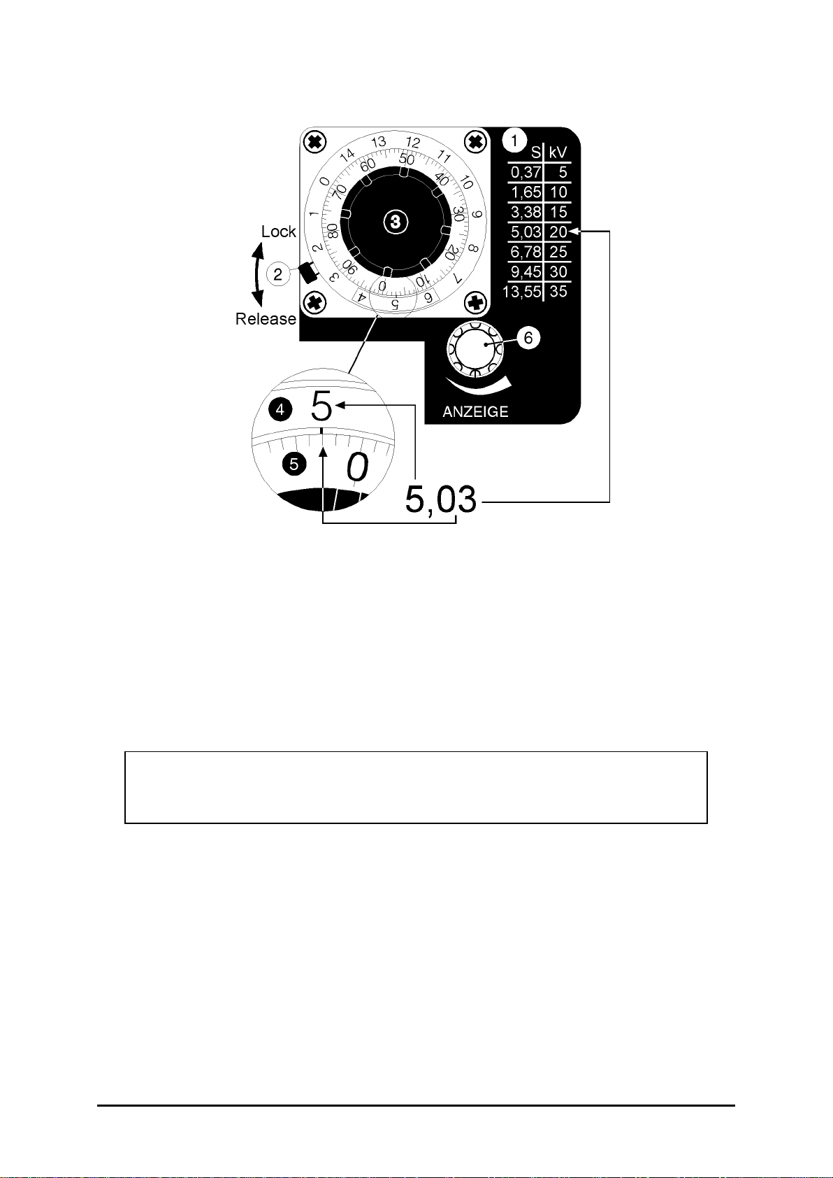
The required test voltage level is set via a rotary scale Ž••(see figure). The
display on the rotary scale is given in millimetres (corresponding to the distance
between the spheres in the sphere gap). In order to set a given
voltage
(in kV), the
corresponding
distance
(S in mm) must be read off from the chart Œalongside the
rotary knob. Caution! The scale is different on the II RT-F.
Subsequently release the lock of the rotary knob by moving lever •in counter-
clockwise direction.
Setting is now carried out with the black inner part of rotary knob Ž. The numeric
value before the comma (decimal point) must appear in the window •of the rotary
knob, the numeric value after the comma must be set with the inner ring •(linked to
the black knob).
After setting, lock the rotary knob again by moving lever •in clockwise direction.
If a voltage value is to be set which is not listed in the chart on the tester, the corres-
ponding setting can be determined from the tables in the Annex (see page 20).
!CAUTION! !
The setting range of the rotary scale is limited mechanically
below the value 0.0 and above the value 13.55.
Forcible turning beyond these values will result in
destruction of the rotary scale.
Operating Manual Isotest II T / II RT Page 7
1.3.2 Setting the Display Sensitivity
Adjust the display sensitivity to the different load and testing conditions with adjust-
ment knob "Anzeige" ‘. There are four levels for setting.
If, after commissioning the tester and inserting the test electrode, a continuous
buzzer sounds, reduce the display sensitivity by turning the adjustment knob in
clockwise direction until the continuous buzzer stops (see Checklist point 1.2).
!The reduction in the display sensitivity has no influence on !
the level of the set voltage.

Page 8Operating Manual Isotest II T / II RT
2Acoustic Signals during the Test Procedure
During examination of the test object, the Isotest tester indicates pores and imper-
missible operating statuses by means of acoustic signals.
2.1 Flaw (Pore)
A flaw (pore) detected during scanning of the test object with the test electrode is
signalled by a buzzer sounding. A flaw can also be clearly recognised optically by
the bundling of the high voltage sparks.
The duration for which the buzzer sounds depends on the size of the flaw and the
test speed.
2.2 Exhaustive Discharge Protection of the Battery
All Type II T/II RT(-F) testers have a special electronic system which detects when
the battery voltage has dropped below a preset value and indicates this by the buzzer
sounding continuously when the tester is switched on.
The measure prevents a damaging exhaustive discharge of the battery and ensures
a reliable function (see Checklist point 1.2).
2.3 Lack of Earth Connection
!This section must be read particularly carefully as the safe !
operation and reliable function of the tester are dependent
on correct earthing!
The safest and most reliable method of earthing is a direct conductive connection
from the metal sheath of the test object to the earth connection of the Isotest tester.
Wherever possible, direct earthing should always be preferred to all other methods of
earthing.

Operating Manual Isotest II T / II RT Page 9
With this method of earthing, first connect the plug of the earthing cable supplied
(15 m) to the earthing socket of the tester. In order to prevent unintentional removal
of the plug, hook the trigger snap attached to the earthing cable to the metal loop on
the leather carrying case.
!In order to minimise the possibility of errors when earthing, !
the lack of an earthing plug in the earthing socket will be
signalled by the buzzer sounding continuously.
The earthing clip on the other end of the cable is now attached to a conducting part
of the test specimen. Ensure that the point to which the earthing clip is fastened is
metallically bare in order to ensure a reliable connection.
!A poor of lack of earthing connection can result not only !
in incorrect measurements but also spark-overs at the
safety switch.
Alternative methods of earthing and possible faults are described in detail in the
Checklist under point 3.1.
2.4 Load Exerted by the Test Specimen
The wide range of possible applications of the ELMED insulation tester can necessi-
tate an adaptation of the display sensitivity to the different loads (see 1.3.2).
Factors for the load area e.g.:
•Type and coat thickness of the insulation
•Different test electrodes
•Size of the test specimen, or
•Moisture.
If an adaptation to the test sensitivity cannot be achieved as described under 1.3.2
(continuous sounding of the buzzer without pore), the load should be reduced by
using a different electrode or drying the test object.

Page 10 Operating Manual Isotest II T / II RT
3Maintenance
In order to ensure the reliability and high standard of quality of your ELMED Isotest
tester over a prolonged period, it should receive regular maintenance.
The observation of the prescribed maintenance intervals is a major factor in ensuring
the functional reliability of the tester and in many cases can prevent the need for
expensive repairs. As a reminder, the date of the next inspection is marked on the
test label.
Although thanks to their sturdy and proven design, ELMED Isotest testers are rela-
tively unsusceptible to faults, the following points should nevertheless be observed:
•Do not expose the tester to high humidity or to wetness.
•Clean the plugs and sockets regularly to avoid dirt.
•Do not allow the high-voltage cable to come into contact with hot or sharp
objects.
•Always close the cover of the carrying case to protect the tester.
•Do not throw the Isotest tester or expose it to severe knocks or impacts.

Operating Manual Isotest II T / II RT Page 11
AAnnex
A.1 Technical Data
A.1.1 Power Supply
Supply voltage: NC battery 6 V / 6 Ah
Pb battery 6 V / 6.5 Ah
Power consumption: 1 - 2 amperes
Test duration
•During continuous operation: approx. 3 hours
•During cyclic operation: approx. 9 hours
A.1.2 Test Voltage
Voltage form: unipolar pulses
Pulse repetition period: approx. 10 µs
Pulse repetition frequency: 25 - 30 Hz
Current (effective value): approx. 40 mA
A.1.3 Dimensions and Weights
Length: 280 mm
Height: 235 mm
Width: 100 mm
Length of high-voltage cable: 1500 mm
Weight incl. handle: 4.5 kg
Weight of the battery: 1.0 kg

Page 12 Checklist for Insulation Tests
Checklist
for the Supervision of Insulation Tests
(to DIN 30 672) using the ELMED Isotest.
1. Test of Readiness for Operation
1.1 Battery
(Varta 5M6 6 V/6 Ah or Sonnenschein 6 V/6.5 Ah)
Has the battery state of charge been checked correctly?
This test can be performed using the ELMED battery charger (see operating
manual for the battery charger).
1.2 Meaning of the Acoustic Signals
A brief buzzer sound when the test button is pressed indicates that the tester
is ready for operation.
FAULT
Buzzer does not sound when the test button is pressed.
CAUSE REMEDY
Main switch on tester has not been
turned on. Turn main switch to ON or I
No battery installed in tester Install battery
Battery discharged Replace battery or inspect old
battery and recharge.
Fuse blown Check fuse (VT/VRT only) and
replace, if necessary
Technical defect in the tester Send in tester for inspection

Checklist for Insulation Tests Page 13
FAULT
Buzzer sounds continuously when the test button is pressed.
CAUSE REMEDY
No or incorrect earthing connection
(valid only for testers with plug-in earth connection:
ISOTEST Type II T / II RT from Serial No. 14796
ISOTEST Type VT / C-VRT from Serial No. 21 000
or from October 1991
The earthing plug must be pushed
into the earthing socket up to the
stop. There must be no material
from the leather carrying case
between plug and socket.
Idle - no electrode contact with the test
specimen
Battery charge too low
ELMED Isotest testers are equipped with
exhaustive discharge protection
Replace battery or inspect old
battery and recharge.
During the test - with test electrode
in contact with the test specimen
Excessive energy flow e.g. due to
moisture Reduce the display sensitivity at
the adjustment knob until the
continuous signal stops. The
reduction in the display sensitivity
has no effect on the level of the set
voltage!!
In other cases, a "continuous buzzer" is the signal for a detected flaw in the
test specimen!

Page 14 Checklist for Insulation Tests
2Test Voltage
2.1 Check whether the test electrode has high voltage as follows:
Switch on the tester and hold the test button depressed. When the electrode
is now earthed, a continuous spark-over must occur. The buzzer sounds
continuously.
2.2 Is the test voltage correctly set?
DIN 30 672, section 5.5.5, prescribes:
The test voltage is 5 kV + 5 kV per mm of coat thickness.
Caution: Beware of overlapping areas of resheathings or works sheathings.
In the case of polyurethane-tar or epoxy resin coatings, observe DIN 30 667
and the manufacturer's instructions.
2.3 Is the test voltage monitored with a sphere gap?
DIN 30 672, section 5.5.5, prescribes a sphere gap as obligatory. Point gaps
are particularly susceptible to changes in atmospheric pressure and humidity
and can, under certain circumstances, result in seriously incorrect settings of
the test voltage.
ELMED testers have an automatic control system with integral sphere gap.
The function of the sphere gap can be heard as a light tapping sound in the
tester or test rod. Monitoring of the test voltage using a separate measuring
spark gap is not necessary thanks to the continuous self-calibration of the test
voltage.

Checklist for Insulation Tests Page 15
3Earthing
In general, a safe and reliable test is only possible with proper earthing. An
incorrect or faulty earth can, under certain circumstances, result in electrisa-
tion of the tester. This can be ruled out with proper use and earthing of the
tester.
3.1 Methods of Earthing
The conductive connection between the object to be tested and the Isotest can
be created in various ways.
3.1.1 Direct connection (earthing) between test objective and Isotest
With this method of earthing, the earthing cable supplied (15 m) is connected
to the tester via the earthing plug (see section 1.2). The earthing clip at the
other end of the earthing cable is now attached to a conductive part of the test
specimen. Ensure that the point to which the earthing clip is fastened is
metallically bare in order to ensure a reliable connection
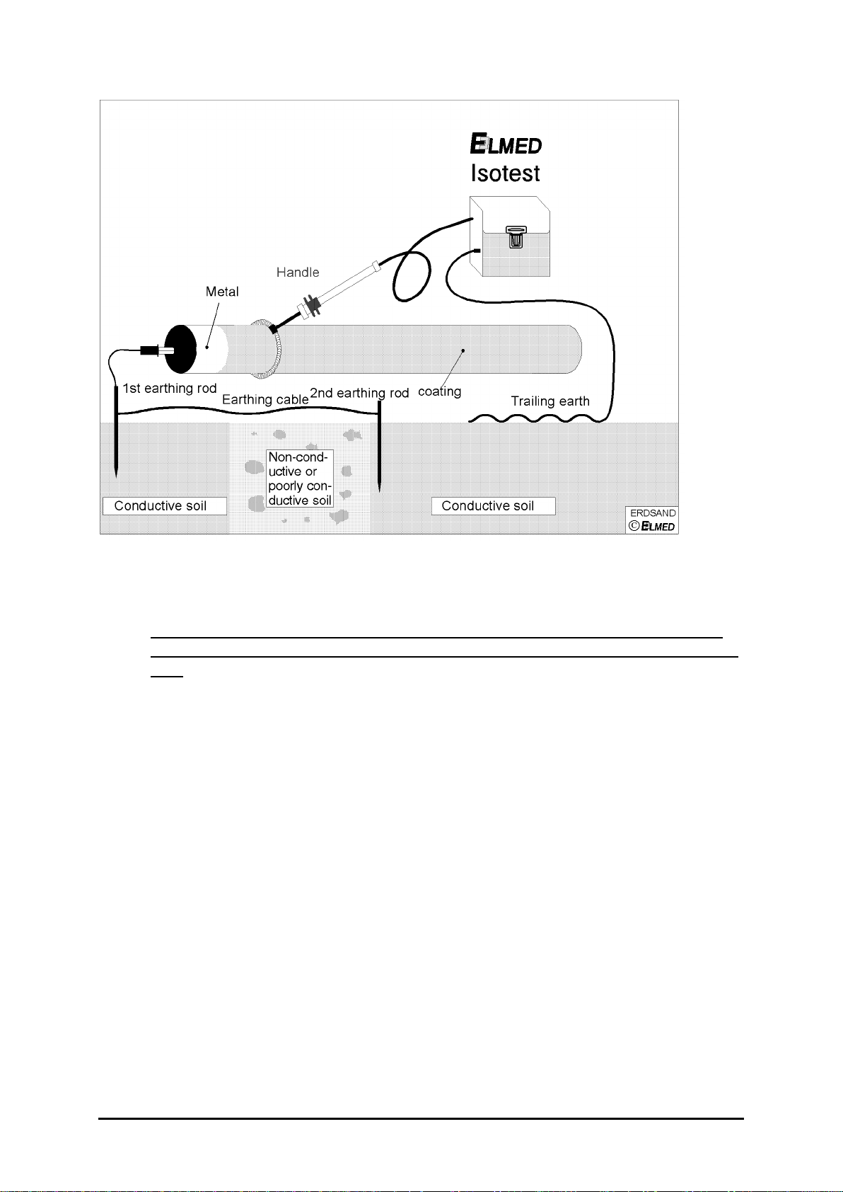
3.1.2 Indirect earthing with the earthing rod and trailing earth
With this method of earthing, the test specimen is connected to the ground at
an accessible and metallically bare point using the earthing rod. (Push the
earthing rod as far into the ground as possible.) Connect the earthing clip to a
metallically bare part of the test specimen (pipe, tank, etc.). Ensure that the
section to be tested and the earthing point are electrically conductive, i.e. are
not connected e.g. via insulators. The connection between the ground and the
insulation tester is effected via the trailing earth, whereby the earthing plug of
the trailing earth is connected to the earthing socket of the Isotest.
As, from experience, we know that problems are frequently encountered with
the indirect earthing method, the following table contains a list of the possible
faults and their remedies:

Page 16 Checklist for Insulation Tests
FAULT REMEDY
Reduced conductivity of the ground due
to wooden boards, insulating materials,
asphalt surfacing or extremely dry soil.
If possible employ "direct earthing",
see 3.1.1, or draw trailing earth
over conductive ground (see figure
on page 17). Bridge the poorly
conductive ground with a second
earthing rod and earthing cable
(see sketch, page 5).
Insufficient contact area between the
trailing earth and the ground. Use
ELMED
trailing earths. They
consist of 6.5 m long bronze double
coils for optimum earthing. Do not
use "home-made" earths!
The Isotest tester is earthed, but not the
test specimen. Connect the test specimen to the
ground using the earthing rod. Use
only
ELMED
earthing rod supplied.
Do not use "home-made" earths!
Poor conductive link between the test
specimen and the ground. In view of the ground conditions
(sand, extremely dry or stony soil) it
can be expedient to soak the point
at which the earthing rod is inserted
into the ground with water. Clean
point at which the earthing clip of
the earthing rod is connected to the
test specimen (metallically bare).
Pipe, tank, etc. is supported on blocks or
suspended on lifting belts. Connect the pipe or tank from a
metallically bare point to the ground
using the earthing rod.
Lines with cathodic protection can be
interrupted by insulators. Earth behind the last insulator or:
Direct earthing.
Checklist for Insulation Tests Page 17
Figure: Trailing earth for non-conductive or poorly conductive soil
All insulated cables (e.g. the supplied earthing cable) are quite unsuitable as
trailing earths. This applies even if an iron chain or large nut is attached to the
end.
3.1.3 Special forms of earthing
If, due to the confines of the process, earthing as described in section 3.1.1
and 3.1.2 is not possible, it is possible to use a capacitive earth. Since in such
cases, conditions specific to the particular application have to be taken into
consideration, please contact
ELMED
beforehand in order to enable us to
recommend a solution tailored to your particular application.

Page 18 Checklist for Insulation Tests
4Test Procedure
4.1 Is an Automatic Controller Installed in the Tester?
If the tester does not have an automatic controller, the test voltage set under
no-load can drop to extremely low values due to capacitor effect, creeping
discharges and pipe moisture.
The fact that individual flaws may nevertheless be indicated does not mean
that all the flaws are actually being detected. ELMED Isotest testers have an
integral sphere gap and an automatic controller which hold the preset voltage
constant even under load.
4.2 Are the Test Electrodes in Order as per DIN 30 672, Section 5.5.5?
4.2.1 Has the spiral electrode appropriate to the pipe diameter been selected?
The electrode must be flush on all sides. It must not sag, as this will result in
incorrect measurements.
4.2.2 Has the test brush appropriate to the pipe diameter been selected?
The electrode must be in contact with the pipe over the full brush surface.
Gaps between pipe and brush will result in incorrect measurements.
4.2.3 Are the brush electrodes solid brushes?
Thanks to their higher stability, solid brushes with continuous brush cover can
ensure the necessary full contact with the pipe surface over a long period of
operation. Electrodes with only individual bunches of bristles can easily result
in incorrect measurements due to bent bristles.
4.2.4 Are the brushes still in order?
Even the best brushes wear after a time. Worn or severely bent bristles lead
to the above-mentioned gaps and thus to incorrect measurements. Install new
brushes!
4.2.5 Do not use brush electrodes with plastic guide wheels!
Non-conductive plastic guide wheels can mask point flaws and thus result in
incorrect measurements.

Checklist for Insulation Tests Page 19
4.3 Special Tests
4.3.1 Subsequent Testing of Contact Surfaces, Slide Valves, etc.
Spirals or round brushes cannot be used to test contact surfaces of supporting
belts, supports, branches, slide valves, etc. A separate test with flat brush
electrodes is necessary here.
4.3.2 Correct Testing of Socket Pipes
The insulation of the insertion end of pipes for socket connections applied at
the factory mean that there is no conductive connection between the two
pipes. The last pipe laid can be easily earthed with the earthing cable of the
tester, but not the last pipe but one. This is of significance particularly during
the examination of the subsequent socket insulation. In such cases, capaci-
tive earthing can be expediently employed (see section 3.1.3).
Page 20 Operating Manual Isotest II T / II RT
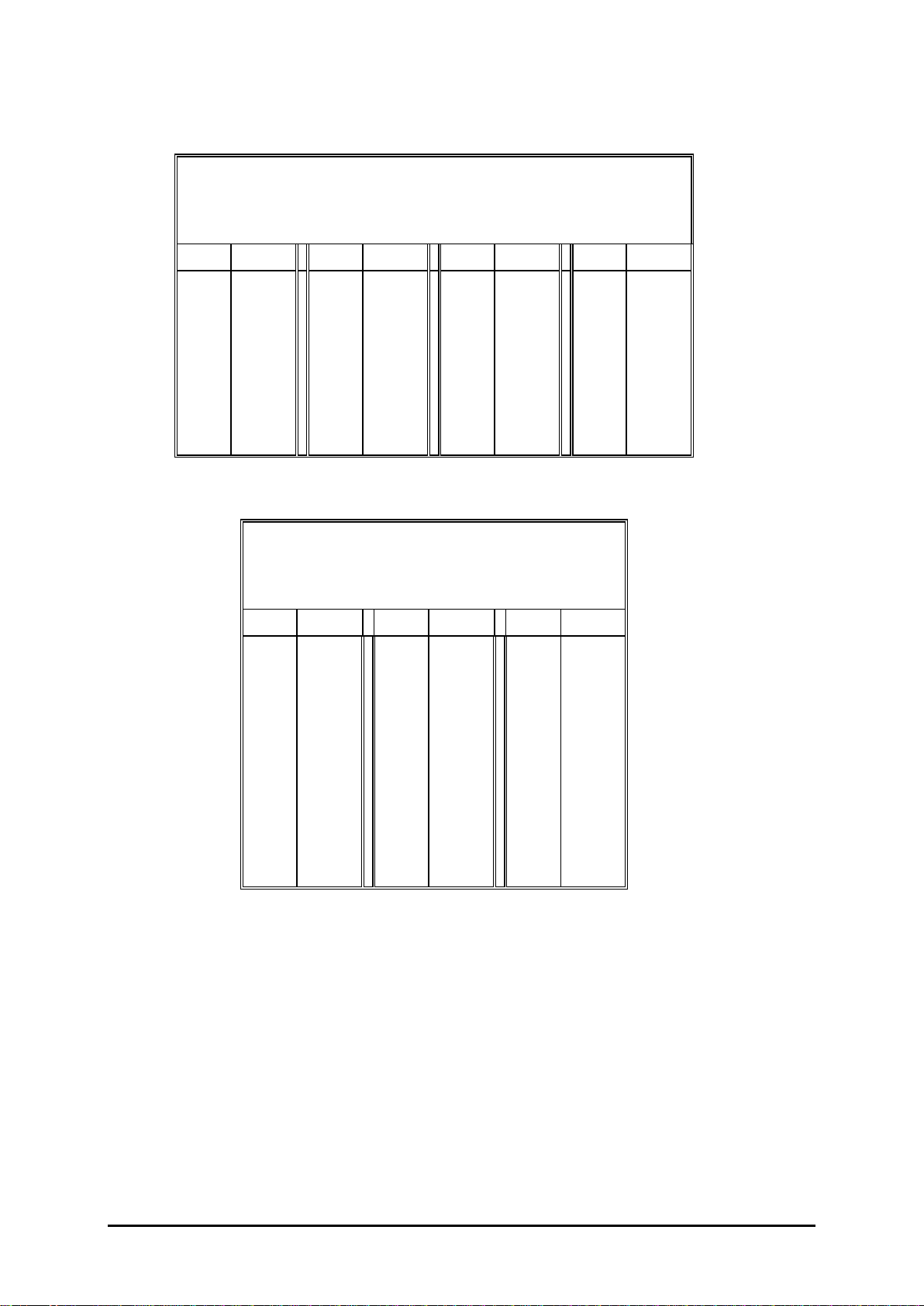
CTables for Intermediate Values of the Test Voltage
! For standard model only !
II RT
kV SkV SkV SkV S
5.0
5.5
6.0
6.5
7.0
7.5
8.0
8.5
9.0
9.5
10.0
0.37
0.47
0.56
0.67
0.79
0.92
1.05
1.20
1.35
1.51
1.65
10.5
11.0
11.5
12.0
12.5
13.0
13.5
14.0
14.5
15.0
1.84
2.02
2.19
2.36
2.54
2.71
2.88
3.05
3.22
3.38
16.0
17.0
18.0
19.0
20.0
21.0
22.0
23.0
24.0
25.0
3.71
4.02
4.35
4.71
5.03
5.37
5.69
6.03
6.39
6.78
26.0
27.0
28.0
29.0
30.0
31.0
32.0
33.0
34.0
35.0
7.26
7.77
8.30
8.86
9.45
10.04
10.70
11.45
12.35
13.55
! For testers with micro-drive only !
II RT-F
kV SkV SkV S
2.5
3.0
3.5
4.0
4.5
5.0
5.5
6.0
6.5
7.0
7.5
8.0
8.5
9.0
9.5
0.36
0.41
0.46
0.52
0.57
0.62
0.78
0.93
1.12
1.32
1.53
1.75
2.00
2.25
2.52
10.0
10.5
11.0
11.5
12.0
12.5
13.0
13.5
14.0
14.5
15.0
16.0
17.0
18.0
19.0
2.78
3.07
3.36
3.65
3.93
4.23
4.52
4.80
5.08
5.36
5.64
6.18
6.70
7.25
7.85
20.0
21.0
22.0
23.0
24.0
25.0
8.43
8.99
9.58
10.21
10.87
11.58
This manual suits for next models
1
Table of contents
Other ELMED Test Equipment manuals


