DIMAX GROUP Konner & Sohnen KS 4100iE User manual

KS 4100iE
KS 8100iE
Inverter Generator
Inverter Generator
in Soundproof Housing
EN
Please, read this manual
carefully before use! Owner’s Manual
KS 2000i S
KS 4000iE S

INTRODUCTION
SAFETY INFORMATION 1
Thank you for your purchase of Könner & Söhnen products. This manual contains a brief description of
safety, use and debugging. More information can be found on the ocial manufacturer’s website in the
support section: ks-power.de/betriebsanleitungen.
You can also go to the support section and download the full version of the manual by scanning the QR
code, or on the website of the ocial importer of Könner & Söhnen products: www.ks-power.de/en.
Manufacturer reserves the right to make alterations into the generators, which may not be reected in this
manual. Pictures and photos of the product may vary from its actual appearance. At the end of this manual,
You may nd contact information which you are free to use in case of any issues occurrence.
All data, specied in this operation manual is the most up to date for the moment of its publishing. The
current list of service centers you can nd at the website of ocial importer: www.ks-power.de/en.
Do not use the generator in rooms with poor ventilation or in conditions of excessive humidity. Do not
place the generator in water or on moist soil. Do not expose the generator to rain, snow, as well as to direct
sunlight for a long time. Place the generator on a at, hard surface, away from ammable liquids/gases
(at a minimum distance of 1 m). Keep unauthorized persons, children, and animals away from work area.
Wear safety shoes and gloves.
We care about the environment, therefore, we consider it expedient to save
paper and leave in print a short description of the most important sections.
Be sure to read the full version of the manual before
getting started!
Failure to follow the recommendations marked with this
sign may lead to serious injury or death of the operator
or third parties.
Useful information while operating the machine.
ATTENTION – DANGER!
IMPORTANT!
ELECTRICAL SAFETY 1.1
The generator produces electricity that may lead to an electric shock while neglecting compliance regulations.
All connecting the generator to the network must be made by certied electrician in accordance with all elec-
trical rules and regulations. Connect the generator to the protective ground before operation. Wires with
damaged or spoiled insulation should be replaced. You should also replace worn, damaged or rusty contacts.
The device generates electricity. Follow safety precautions
to avoid electric shock.
Using device for other purposes deprives the right for
free warranty.
ATTENTION – DANGER!
IMPORTANT!
Be careful. Do not operate the generator, if you are tired,
under the inuence of drugs or alcohol. Inattention may
cause a serious injury.
ATTENTION – DANGER!
www.ks-power.de/en |17

PRECAUTIONS WHEN WORKING WITH
GASOLINE GENERATOR 1.2
Do not start the generator operation upon presence of electric load! Disconnect the load before you stop
the engine. Only unleaded gasoline is recommended for the generator. It is forbidden to use
kerosene or other fuel types. Before running the generator, it is necessary to dene the place and means of
its emergency stop. Do not refuel the running generator.
Fuel contaminates the land and groundwater. Do not
allow the leaking gasoline from the tank!
ATTENTION – DANGER!
MAIN OVERVIEW 2
Manufacturer reserves the right to make changes and/or
improvements in design, components set and technical
attributes without notice and without incurring
obligation. The pictures in this manual are schematical
and may not match the parameters of original product.
IMPORTANT!
2
1
9
10
111213
3 4 5 6 78
2
3
4
1
6
7
5
MODELS KS 4100iE, KS 8100iE
1. Fuel tank cap
2. Fuel level indicator
3. Control panel
4. Carrying handles
5. Manual starter (only for model KS 4100iE)
6. Transport wheels
7. Oil-depth gage
1. Multifunctional engine switch
2. Oil level indicator
3. Overload indicator
4. Voltage indicator
5. Reset button
6. 12V DC fuse
7. Economy mode switch (ЕCОN)
8. LED display
9. Generator parallel socket
10. Ground terminal
11. 2x16А AC outlets
(for model KS 8100iE 1x16А, 1*32А
outlets)
12. 12V/8.3A DC outlet
13. 2 USB-Outputs
www.ks-power.de/en |18

1. 2 USB-Outputs
2. Economy mode switch (ЕCОN)
3. LED display
4. 1x16А AC outlet
5. Ground terminal
6. Reset button
7. Generator parallel socket
1. 2 USB-Outputs
2. Economy mode switch (ЕCОN)
3. LED display with oil level indicator, overload
indicator, voltage indicator
4. 12V DC fuse
5. 2x16А AC outlets
6. Ground terminal
7. Generator parallel socket
8. Reset button
9. 12V/8A DC outlet
MODEL KS 4000iE S
MODEL KS 2000iS
1. Fuel tank cap air vent
2. Carrying handles
3. Control panel
4. Manual starter
5. Air choke
6. Maintenance cover
(on the other side of the generator)
1. Fuel tank cap
2. Carrying handles
3. Control panel
4. Manual starter
5. Transport wheels
6. Maintenance cover
7. Multifunctional engine switch
3
54
6
7
4
2
1
5
3
213
7
76
8 691
1
542
2 3 4
5
6
www.ks-power.de/en |19

Model KS 4100iE KS 8100iE KS 2000i S KS 4000iE S
Voltage, V 230
Maximum power, kW 4.0 8.0 2.0 4.0
Nominal power, kW 3.6 7.2 1.8 3.5
Frequency, Hz 50
Current, A (max.) 17.4 34.8 8.7 17.4
Outlets 2*16A 1*16A
1*32A 1*16A 2*16A
Engine start manual/electro electro manual manual/electro
Fuel tank volume, l 12.5 20 4 12.5
LED display voltage, frequency,
working hours voltage, frequency,
working hours voltage, frequency,
working hours multifunctional*
Noise level Lpa (7m)/Lwa, dB 72/95 72/95 64/87 66/91
Output 12V, A 12V/8,3A 12V/8,3A -12V/8,3A
USB-Outputs 5V/1A
5V/2.1A
5V/1A
5V/2.1A
5V/1A
5V/2.1A
5V/1A
5V/2.1A
Engine model KS 240i KS 480i KS 100i KS 240i
Engine volume, cm3223 458 79.7 223
Engine type gasoline powered one-cylinder, four-stroke air-cooled
Engine power, hp 7.5 16 2.5 7.5
Generator parallel socket + - + +
Crankcase volume, l 0.6 1.1 0.4 0.6
Power factor, cos φ 1 1 1 1
Dimensions (L*W*H), mm 600*420*425 685*500*553 510*310*525 630*475*570
Lithium battery, Ah 1.6 1.6 - 1.6
Net weight, kg 38 68 18 40
Protection class IP23M
Nominal voltage tolerance – max. 5%
To ensure reliability and increase the engine service life, peak powers may be slightly limited by circuit breakers.
The optimal operating conditions are ambient temperature of 17-25°C, barometric pressure of 0.1 MPa (760 mm Hg),
and relative humidity of 50-60%. Under these environmental conditions, the generator can provide maximum perfor-
mance in terms of the declared specications.
In the event of deviations from these environmental indicators, the generator performance may vary.
Please note that in order to preserve the long service life of the generator, continuous loads of more than 80% of the
nominal power are not recommended.
*Multifunctional LED-display: load, fuel level, voltage, frequency, working hours; overload indicator, voltage indicator, oil
level indicator.
20
www.ks-power.de/en |
SPECIFICATIONS 3

It is recommended to ground the generator before operating it for the first time. Before starting the device,
remember that the total power of the connected power consumers should not exceed the nominal power
of the generator.
TERMS OF USE
OF INVERTER GENERATOR 4
GENERATOR OPERATION 5
To avoid electric shock due to poor-quality electrical
appliances or improper use of electricity, the generator
must be earthed using a high-quality insulated conductor.
IMPORTANT!
Make sure that the control panel, the blinds and the
underside of the inverter are well cooled and protected
against the ingress of small solids, dirt, and water.
Improper operation of the cooler can cause damage to
the motor, inverter or alternator.
IMPORTANT!
DC FUSE
The DC protector automatically switches to “OFF” when the current of the operating electrical device is
higher than the rated current. To use this equipment again, turn on the DC fuse again by pressing the “ON”
button.
OIL LEVEL INDICATOR
When the oil level falls below the level required for operation, the oil level indicator lights up, and then the
engine stops automatically. The engine will not start until oil is added.
AC INDICATOR
When the generator is running and producing electricity, the AC indicator light is on.
If the DC fuse turns off, reduce the load of the connected
electrical device. If the DC protector turns off again, stop
operation and contact your nearest Könner & Söhnen
service center.
IMPORTANT!
OVERLOAD INDICATOR
The overload indicator lights up when the connected generator is overloaded, the inverter control unit
overheats or the AC output voltage rises.
If the overload indicator goes on, the engine will continue to operate, but the generator will no longer
produce electricity. In this case, you must perform the following steps:
1. Turn off all connected electrical appliances and stop the engine.
2. Reduce the total power of the connected devices until the nominal power of the generator is reached.
3. Check if the vent grid is clogged. Remove excess dirt or debris, if any.
4. After checking, start the engine.
The overload indicator may light up within several
seconds after start-up or when connecting electrical
devices requiring a high starting current, such as a
compressor or voltage indicator. However, this is not a
malfunction.
IMPORTANT!
www.ks-power.de/en |21
FUEL TANK CAP AIR VENT (FOR MODELS KS 2000iS, KS 4000iE S)
The fuel cap is equipped with a vent for air supply to the fuel tank. When the engine is running, the vent
must be in the “ON” position (OPEN). This will allow fuel to enter the carburetor for engine operation.
When the generator is not in use, close the vent to the “OFF” position.
GROUND TERMINAL
The ground terminal forms a ground line to prevent electric shock. If the electrical appliance is grounded,
the generator must also be grounded.
CHECKING THE FUEL LEVEL
1. Unscrew the fuel cap and check the fuel level in the tank.
2. Fill the fuel tank to the fuel filter level.
3. Tighten the fuel cap securely.
4. For silent models of inverter generator, open the air intake vent on the fuel cap.
Recommended fuel: unleaded gasoline.
Fuel tank volume: see specifications table.
CHECK BEFORE GETTING STARTED 6
Wipe up spilled fuel immediately with a clean, dry, soft
cloth, as the fuel may harm painted surfaces or plastic
parts.
IMPORTANT!
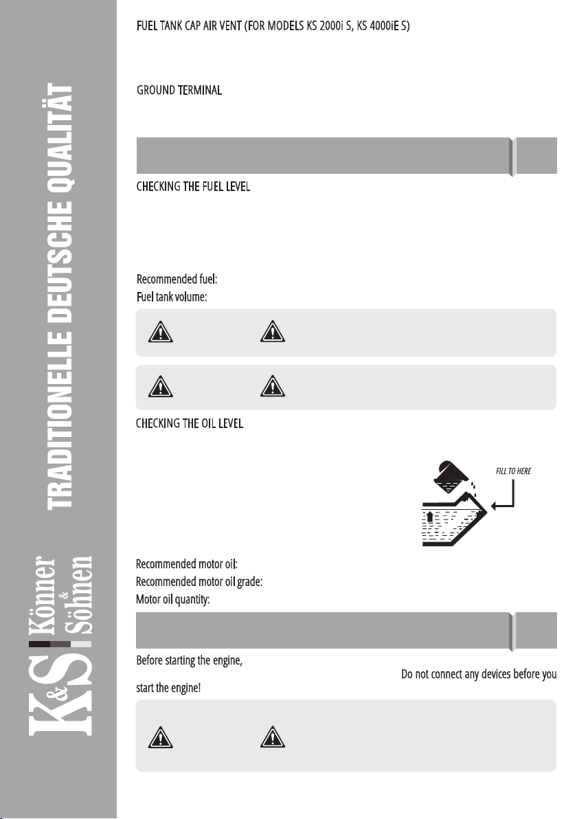
CHECKING THE OIL LEVEL
The generator is transported free of motor oil. Do not start the engine until it is filled with sufficient amount
of motor oil.
1. Unscrew the oil dipstick and wipe it out with a clean cloth.
2. Insert the dipstick without screwing it in.
3. Check the oil level by a mark on the oil dipstick.
4. Add oil if its level is below the mark on the oil dipstick.
5. Screw on the dipstick.
Recommended motor oil: SAE 10W30, SAE 10W40.
Recommended motor oil grade: API Service SG type or higher.
Motor oil quantity: see specifications table.
FILL TO HERE
Use only unleaded gasoline. Using leaded gasoline can
cause serious damage to the inside of the engine.
IMPORTANT!
Before starting the engine, make sure that the rated power of power consumers matches with the power
of generator. Do not exceed the nominal power of the generator. Do not connect any devices before you
start the engine!
GETTING STARTED 7
Do not change the controller settings in terms of the
amount of fuel or speed governor (this adjustment
was made at the factory). Otherwise, this may result in
changes in the engine operation or its failure.
IMPORTANT!
www.ks-power.de/en |22
In the power supply mode, the generator should operate
no longer than 1 minute in the range from nominal to
maximum power.
ATTENTION – DANGER!
COMMISSIONING
1. Fill the crankcase with engine oil. The recommended amount of oil for each model is indicated in the
specification chart.
2. Check oil level with an oil dipstick. It should be between the MIN and MAX marks on the oil dipstick.
3. Check fuel level.
In the first 20 operating hours of the generator, the following requirements should be met:
1. During commissioning, do not connect power consumers, the power of which exceeds 50% of the
nominal (operating) power of the device.
2. After commissioning, be sure to change the oil. It is better to drain oil while the engine is still hot after
operation to ensure quick and complete oil draining.
Before starting the generator, connect the ground wire to
the ground terminal.
IMPORTANT!
ENGINE START
Useful tip: If the engine stalls or does not start, turn
the engine switch to the “ON” position, and then pull
the manual starter. If the oil level indicator flickers for
several seconds, add oil and restart the engine.
IMPORTANT!
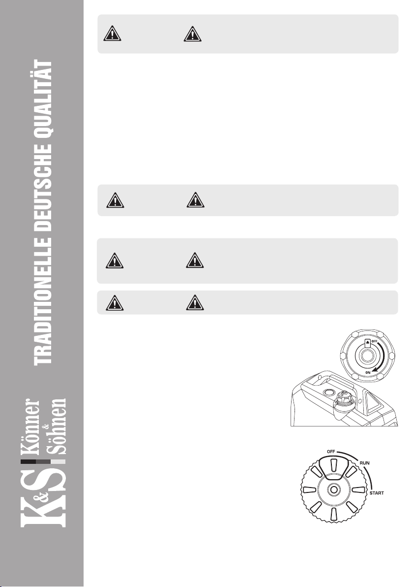
FOR MODELS KS 4100iE, KS 8100iE, KS 4000iE S
1. Check oil level.
2. Check fuel level.
3. Open the vent on the fuel cap to the “ON” position (for model
KS 4000iE S, see fig. 1).
4. Turn the Multifunctional engine switch to the “START” position.
5.1 For manual start (models KS 4100iE, KS 4000iE S), pull the
manual starter until a slight resistance is felt, then pull it toward
you relatively sharply. Slowly turn the manual starter by hand, do
not release it abruptly.
5.2 For electric start, press the red button on the multifunctional
engine switch (fig. 2)
6. After starting the engine, turn the Multifunctional engine
switch to the “RUN” position (fig. 2).
Fig. 1
Fig. 2
Each time you start the generator, be sure to check oil and
fuel level
IMPORTANT!
FOR MODEL KS 2000i S
1. Check oil level.
2. Check fuel level.
3. Open the vent on the fuel cap to the “ON” position.
4. Turn the air choke control knob to the “START” position (Fig. 3)
www.ks-power.de/en |23

Useful tip: to ensure long-term operation of the generator
engine, it is important to observe the following tips:
- Before connecting the load, allow the engine to run for 1-2 minutes to warm it up.
- When disconnecting the load after lengthy operation, do not turn off the generator. Allow
the generator to run idle for 1-2 minutes so that it cools down.
IMPORTANT!
5. Pull the manual starter until a slight resistance is felt, then pull
it toward you relatively sharply. Slowly turn the manual starter by
hand, do not release it abruptly.
6. Turn the air choke control knob to the “RUN” position.
Fig. 3
Do not connect two or more devices at a time. The start-
up of many devices requires high power. Devices should be
connected one at a time according to their power rating.
Do not connect any power consumers within the first
2 minutes after the generator has been started.
ATTENTION – DANGER!
“ON” MODE
When the ECON switch is in the “ON” position, the control unit monitors the engine speed, reducing it
commensurate with the connected load. If the engine speed is not enough to generate electricity to provide
the load, the control unit will automatically increase the engine speed.
As a result, fuel consumption is optimized and noise levels are reduced.
The ECON switch must be set to “OFF” to increase
engine speed to nominal. When connecting multiple
power consumers to the generator, be sure to first
connect the one with the highest starting current, and
the device with the lowest starting current should be
connected last.
IMPORTANT!
ECON FUNCTION
1. Start the engine.
2. Set the ECON switch to “ON”.
3. Plug the device into an AC outlet.
4. Make sure the AC indicator light is on.
5. Turn on the electrical device.
FUNCTIONAL DESCRIPTION
OF INVERTER GENERATORS 8
“OFF” MODE
The ECON switch must be set back to “OFF” when using electrical devices requiring a high starting current,
such as a compressor or submersible pump.
The ECON switch must be set back to “OFF” when using
electrical devices requiring a high starting current, such
as a compressor or submersible pump.
IMPORTANT!
www.ks-power.de/en |24
DISCONNECT ALL DEVICES BEFORE STOPPING THE GENERATOR!
Do not stop the generator with the devices turned on. This may disable the generator or devices connected
to it!
Use care when the generator is running!
You can use the generator if the voltmeter indicates
a value of 230V ±10% (50 Нz).
IMPORTANT!
PARALLEL FUNCTION
The total output power of the generators can be increased by connecting two inverter generators together
using the Parallel Unit KS PU1 from Könner & Söhnen. Parallel connection of two identical generator models
ensures double nominal output power of these models. When connecting generators of different capacities
using the Parallel function, the output power is two times the nominal power of the generator with lesser
capacity. The total output power of the generators can be increased by connecting two inverter generators
together using the Parallel Unit. Parallel connection of two identical generator models ensures double
nominal output power of these models. When connecting generators of different capacities using the
Parallel function, the output power is two times the nominal power of the generator with lesser capacity.
When the generators are connected in parallel, the power loss is 0.2 kW of the total rated power that can
be obtained.
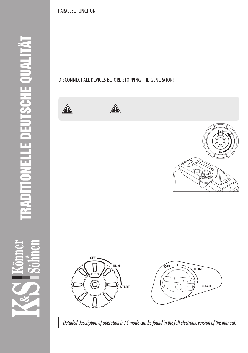
TO STOP THE ENGINE, PROCEED AS FOLLOWS:
FOR MODELS KS 4100iE, KS 8100iE, KS 4000iE S
1. Turn off all devices.
2. Allow the generator to run idle for approx. 1-2 minutes.
3. Turn the Multifunctional engine switch to the “OFF” position
(Fig. 5). м
4. Unplug the devices.
5. After the generator stops, allow it to cool down and close the
vent (for model KS 4000iE S, see fig. 4).
Fig. 4
FOR MODEL KS 2000i S
1. Turn off all devices.
2. Allow the generator to run idle for approx. 1-2 minutes.
3. Set the engine switch to the “OFF” position.
3. Turn the air choke control knob to the “OFF” position (Fig. 6).
4. Allow the generator to cool down.
5. Unplug the devices.
5. Close the air vent on the fuel cap (set to OFF, as shown in Fig. 4).
Fig. 6Fig. 5
Detailed description of operation in AC mode can be found in the full electronic version of the manual.
www.ks-power.de/en |25
IMPORTANT!
CHARGING AN EXTERNAL 12V BATTERY
1. Start the engine.
2. Connect the red wire to the positive (+) terminal of the battery.
3. Connect the black wire to the negative (-) terminal of the battery.
4. Connect the wire to a 12V/8A DC socket on the control panel of the generator.
5. To start charging the battery, set ECON to “OFF”.
6. Turn the 12 V DC fuse to the “ON” position.
- Make sure the ECON mode is off while the battery is being charged (except model
KS 24ViE S).
- Be sure to connect the charger’s red wire to the plus (+) terminal of the battery and the
black wire to the minus (-) terminal of the battery. Do not swap the terminals.
- Connect the charger to the battery terminals securely so that they are not disconnected due
to motor vibrations or other actions.
- To charge the battery properly, follow the instructions in the battery manual.
- The DC protector turns off automatically if the current is higher than the rated current
while the battery is being charged. To restore battery charging, turn on the DC fuse by
pressing the “ON” button.
Never smoke or interrupt battery connections to the
generator while the battery is being charged. Sparks
can cause battery gas to ignite. Battery electrolyte is
poisonous and dangerous and causes severe burns, as
well as contains sulfuric acid.
Avoid contact with skin, eyes and clothing.
ATTENTION – DANGER!
MAINTENANCE 9
This manual compliance! You can find a list of service center addresses on the website of exclusive importer:
www.ks-power.de/en.
www.ks-power.de/en |26

RECOMMENDED OILS 10
The manufacturer shall not be liable for any damage
caused by failure to perform maintenance work.
IMPORTANT!
- If the generator often operates at high temperature or high load, the oil should be replaced every 25
operating hours.
- If the engine often runs in dusty or other harsh conditions, clean the air filter every 10 operating hours.
- If you missed the maintenance time, perform it as soon as possible to save the generator engine.
TECHNICAL MAINTENANCE WORKS
Unit
Action
At each start
First month
or 20 operating
hours
Every 3 months
or 50 operating
hours
Every 6 months
or 100 operating
hours
Every year
or 300 operating
hours
Motor oil
Level check
Replacement
Air lter
Cleaning
Replacement
Spark plug
Cleaning
Replacement
Fuel tank
Level check
Cleaning
Fuel lter Check (clean out)
Upon oil level decrease it is necessary to add the required quantity in order to provide the correct generator
operation. It is necessary to check the oil levels according to technical maintanance schedule.The detailed
description of oil lling and draining can be found in the full version of the manual.
Use oils designed for four-stroke cycle vehicle engines
SAE10W-30, SAE10W-40. Motor oils with other viscosity
levels, may be used only if the average air temperature
in your region does not exceed the limits of the
temperature range, specified in the table.
00C
10W-30, 10W-40
40302010-10-20
AIR FILTER TECHNICAL MAINTENANCE 11
Air filter cleaning is to be performed each 50 hours of the generator operation (every 10 hours in unusually
dusty conditions).
CLEANING THE FILTER:
1. Open the clips on the upper cap of the air lter.
2. Remove the sponge ltering element.
3. Remove all dirt deposits inside the hollow case
of the air lter.
4. Thoroughly wash the ltering element in
warmsoapy water.
5. Dry the sponge lter.
6. Dry ltering element is to be moistened by
machine oil and excess oil is to be squeezed out.
www.ks-power.de/en |27

SPARK PLUGS TECHNICAL MAINTENANCE 12
DAMPER AND FLAME ARRESTER
MAINTENANCE 13
Spark plug has to be intact, without soot deposits and to have a correct gap.
SPARK PLUG VERIFICATION:
1. Remove the cap from the spark plug.
2. Remove the spark plug by means of a corresponding spanner.
3. Examine the spark plug. If is is shattered – it is necessary to replace it.
Recommended replacement spark plugs – F7TC.
4. Measure the gap. It has to be within range 0.7-0.8 mm.
5. In case of repeated use, the spark plug has to be cleaned by means of a metal brush.
After that – set the correct gap.
The engine and damper will get very hot after the generator has been started. Do not touch the engine or
damper with any part of your body or clothing during inspection or repair until they have cooled down.
Remove the screws and then pull the protective cover towards you. Loosen the bolts and remove the cover,
screen and ame arrester of the damper. Descale the screen and ame arrester of the damper with a wire
brush.Inspect the screen and ame arrester of the damper. Replace them if they are damaged. Replace
the ame arrester. Replace the screen and cover of the damper. Replace the cover and tighten the screws.
Match the protrusion of the flame arrester to the hole
in the pipe damper.
IMPORTANT!
FUEL FILTER 14
1. Remove the fuel tank cap and fuel lter.
2. Clean the lter with gasoline.
3. Wipe the lter and replace it.
4. Replace the fuel tank cap.
Make sure that the fuel tank cap is tight.
Never use gasoline while smoking or in the immediate
vicinity of an open flame.
IMPORTANT!
BATTERY USE 15
STORAGE 15
The generator battery is not subject to service. If the generator is not used for a long time, the battery may
fail. To prolong battery life it is recommended to do battery charging with an external device (not included)
every three months.
Battery warranted – three months from the date of purchase of the generator.
The generator must be stored and transported with a
closed vent at all times!
IMPORTANT!
www.ks-power.de/en |28

BATTERY AND GENERATOR DISPOSAL 17
WARRANTY SERVICE TERMS 18
Storage room has to be dry and free from dust deposits. Storage room also has to be locked away from
children and animals. It is recommended to store and use the generator at temperature of -20°С to +40°С.
Avoid direct sunlight, rain on the generator. When using and storing hybrid generator, gas tank should be
kept indoors at temperatures below +10°С. If the temperature is lower, gas will evaporate. Information on
long-term storage and transportation can be found in the full version of the manual.
To prevent environment damage generator and battery should be separated from ordinary waste. Please
recycle them in the safest way, passing it to special place for disposal.
The international manufacturer warranty is 1 year. The warranty period starts from the date of purchase.
In cases when warranty period is longer than 1 year according to local legislation please contact your local
dealer. The Seller which sells the product is responsible for granting the warranty. Please contact the Seller
for warranty. Within the warranty period, if the product fails because of defects in the production process,
it will be exchanged on the same product or repaired.
All faults caused by the manufacturer during the warranty period will be eliminated free of charge. Warran-
ty repair is carried out only if you have a fully completed warranty card, the Buyer’s signature of acceptance
of the warranty terms, as well as a document supporting the purchase (cash receipt, sales slip or invoice). In
the absence thereof, as well as in the event of errors or corrections not authenticated by the seller’s seal or
illegible inscriptions in the warranty card or tear-o coupon, no warranty repair is carried out, no objections
to quality are accepted and the warranty card is withdrawn by the service center as invalid. The device is
accepted for repair clean and full.
WARRANTY DOES NOT APPLY:
- If the user has failed to comply with the instructions in this manual.
- If the product features damaged or missing identication stickers or labels, serial numbers, etc.
- If product malfunction was due to improper transportation, storage and maintenance.
- In case of mechanical damages (cracks, chips, impact and fall marks, deformation of housing, power
cord, plug or any other components), including those resulting from the freezing of water (ice formation),
provided there are foreign objects inside the unit.
- If the product has been improperly installed and connected to the mains supply or misused.
- If the claimed malfunction cannot be diagnosed or demonstrated.
- If proper operation of the product can be restored following cleaning from dust and dirt, appropriate
adjustment, maintenance, oil change, etc.
- If the product is used for business related purposes.
- If faults are detected, which have been caused by product overload. Signs of overload are molten or
discolored parts as a result of high temperatures, damaged cylinder or piston surfaces, degraded piston
rings or connecting rod bushes.
- The warranty does not cover the failure of the product automatic voltage regulator due to careless han-
dling or mishandling.
- If faults are detected, which have been caused by instability of the user’s power grid.
- If there are faults caused by contamination or fouling such as contamination of the fuel, oil or cooling
system.
Potential faults and troubleshooting methods, as well as average device capacities can be found in the
full version of the manual.
www.ks-power.de/en |29

- If electrical cables or plugs show signs of mechanical or thermal damage.
- In the event of foreign liquids and objects, metal chips, etc. inside the product.
- If the malfunction is caused by the use of non-original spare parts and materials, oils, etc.
- If there are two or more faulty units that are not interconnected.
- If the damage was caused by natural factors such as dirt, dust, humidity, high or low temperature, natural
disasters.
- To quick-wear parts and components (spark plugs, nozzles, pulleys, lter and safety elements, batteries,
removable devices, belts, rubber seals, clutch springs, axles, manual starters, oils, gear).
- To preventive maintenance (cleaning, greasing, washing), installation and adjustment.
- If the product was tampered with, independently repaired or modied.
- In case of malfunctions resulting from normal wear and tear as a result of long-term use (end of life).
- If product operation was not stopped and continued after detecting a malfunction.
- Batteries supplied with equipment are covered by a warranty of three months.
www.ks-power.de/en |30


Polska:
DIMAX International
Poland Sp.z o.o.
Polen, Warczawska, 306B
05-082 Stare Babice,
www.ks-power.pl
Україна:
ТОВ «Техно Трейд КС»,
вул. Електротехнічна 47,
02222, м. Київ, Україна
www.ks-power.com.ua
Россия:
ТД «Рус Энержи К&С»
129090, г.Москва, про-
спект Мира, д.19, стр.1,
эт.1, пом.1, комн.6б, офис
99В
www.ks-power.ru
CONTACTS
Deutschland:
DIMAX International GmbH
Deutschland, Hauptstr. 134,
51143 Köln,
www.ks-power.de
This manual suits for next models
7
Table of contents
Other DIMAX GROUP Portable Generator manuals


