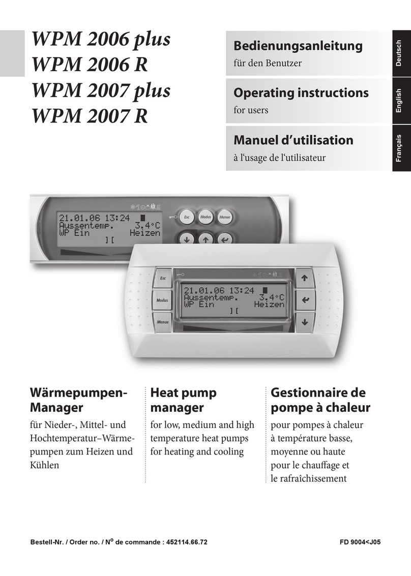
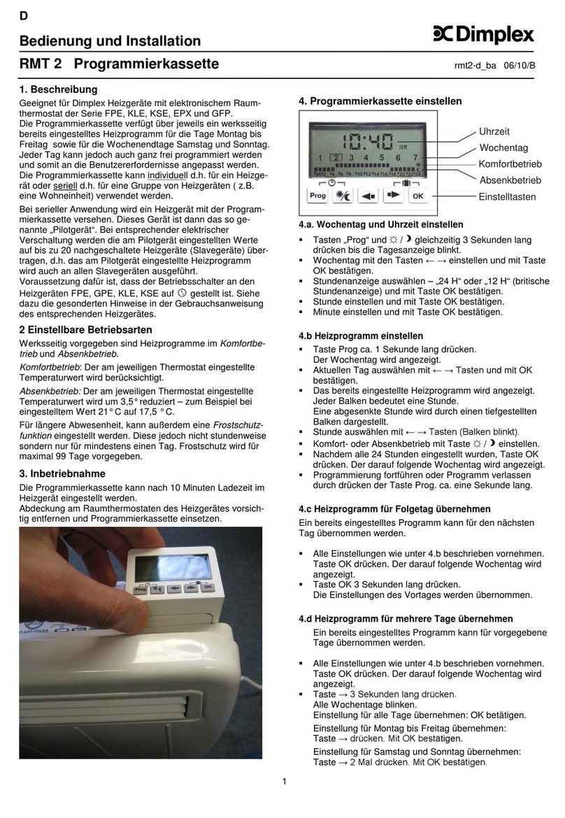
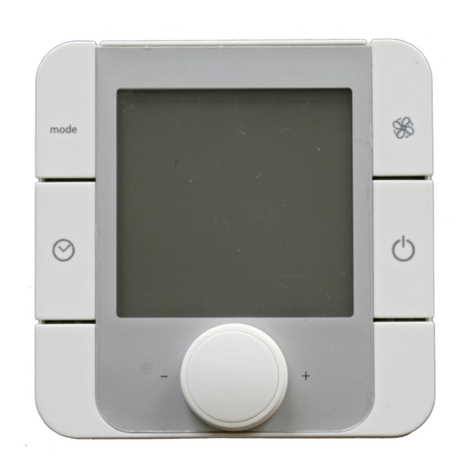
Dimplex ZWU 06E User manual

Installation and operating instructions
ZWU 06E
Central control unit
with timer function
Central control unit for underfloor storage heating and electric storage heaters

2
Table of contents
Content Page
Device description...................................................................... 3
Technical device information...................................................... 4
Installation and operating instructions for technicians ....... 6
Installation options for external sensor ...................................... 7
Circuitry ...................................................................................... 9
Terminal assignment................................................................ 10
Circuit diagrams ....................................................................... 11
Commissioning......................................................................... 14
Overview of factory settings ..................................................... 15
Setting the charge control ........................................................ 17
Necessary commissioning steps.............................................. 19
Commissioning certificate ........................................................ 22
Operating instructions for users .......................................... 24
User interface........................................................................... 25
Operation ................................................................................. 26

3
Device description
The ZWU 06E central control unit controls the charging of an underfloor
storage heating system and/or the charging of storage heaters according
to out
door temperature, adjusters and control signals.
The basic design of the control unit has the basic
functions of a central
control unit as set out in DIN EN 50350. It has the following features:
•
Charging according to outdoor temperature,
•
The ability to process charge release signals from the distribution
network operator (with/without timer function),
•
The ability to output the charge release and the set charge rate to the
storage heaters and underfloor charge controllers,
•
Timer function for forward, backward and spread control,
•
Priority and secondary use of actual service release periods for low
and high tariffs,
•For optional connection to older external sensors, too.
Depending on the unit type connected downstream, an AC and a DC
output are available for the control signal.
Scope of supply
−
ZWU 06E central control unit
−
NTC external sensor with 3 m connection cable
−
Installation and operating instructions
−
Safety notes

4
Technical device information
ZWU 06E central control unit
Connection voltage
AC 230V ~ 50/60 Hz
Permissible voltage range
AC 207 V to 253 V
Power consumption
Approx. 2 VA
Inputs
•External sensor
•
Charge release LF, additional release LZ, multi-function LX
•Frost protection switching FS
Outputs
•DC control signal
•
AC control signal with duty cycle system
•Charge release relay (SH)
Reference variable at terminals ZX, Z0 (storage heaters)
DC 0.91 V to 1.43 V, safety overlap to 1.68 / 1.95 V
Reference variable at terminals ZX, Z0 (underfloor heating)
DC -2.85 V to -3.60 V, safety overlap to -4.35 V
Reference variable at terminals Z2~, Z1~ (storage heaters)
230V~ clocked 30 - 100% duty cycle
Power reserve
Approx. 6 h (runtime and clock)
Communication
Mini-USB to laptop/PC
Supported types of external sensor
•DIN EN 50350 standard sensor:
Dimplex standard sensor DIN,
tekmar series 31,
Schlüter/Deltadore NF,
Birka/Sabi 983,
Grässlin/Frensch RF-N-1,
Dohrenbusch/DRT 25-2k,
DEVI,
Stiebel Eltron,
AEG
•
tekmar series 30
•
Dohrenbusch DRT 25-470
•Schlüter/Deltadore UNI
•
Schlüter/Deltadore RF
•
Grässlin/Frensch WF-R2/WF-E55
•
Birka/Sabi 981
•
DEVI 25-15k
•
Ritter (DRT) 20-500
•
MALAG outdoor temperature sensor
•
Siemens outdoor temperature sensor
•
Siemens 2 outdoor temperature sensor
•
ACEC outdoor temperature sensor
•
Bauknecht PTC
•Witte outdoor temperature sensor
Supported duty cycle systems
30 - 100%, thermo-mechanical and electronic charge controllers
Power rating of duty cycle signal
1 A = 230 W nominal @ AC 230 V (min. resistance 230 Ω)
Supported DC voltages (SELV)
•Dimplex / Bauknecht (0.91 to 1.43 V)
•
tekmar (-3.60 to -2.85 V)
•
tekmar up to year of manufacture 70 (-4.35 to -2.85 V)
•Dohrenbusch DRT (2.65 to 3.00 V)
Power rating of DC signal
Connection of max. 20 charge controllers of type AR 06DCU 4
Nominal switching power of SH relay
1.1 kW

5
Operating/storage temperature
-15°C to +40°C / -20°C to +70°C, condensation not permitted
Protection class
II according to installation (see section “Installation”)
Degree of protection
IP 20 according to EN 60529, according to installation
Standard
DIN EN 50350 and DIN 44576 (draft)
Space requirements
Series mounting casing, 3 modular spaces according to DIN 43880
Fastening
TH-35 mounting rail according to DIN EN 60715
Connecting terminals
Cage clamp terminals for 2.5 mm², tightening torque ≤ 0.5 Nm
Dimensions
See dimension drawing
Weight
Approx. 250 g
External sensor
Sensor type
NTC sensor according to DIN EN 50350 in insulated casing
Connection cable
3 m long (extendable up to a maximum of 100 m)
Protection class
II according to DIN EN 60730-1
Degree of protection
IP54 according to DIN 40050
Dimensions
29 mm × 6.2 mm

6
Installation and operating instructions for technicians
Installing the central control unit
Installation must only be carried out by a technician authorised by the
respective energy supplier/network operator (utility company). The
regulations of the local utility company, as well as the relevant VDE
(Association of German Engineers) regulations are to be observed.
The space required by the device is 3 modular spaces according to DIN
43880. Protection against accidental contact accor
ding to protection
class II is ensured by installing the device in:
•
Small installation distribution board according to DIN 57603/VDE 0603
(e.g. N system distribution board)
•
Installation distribution board according to DIN 57659/VDE 0659.
The charge control
unit should be installed in the coolest location, i.e. the
lowest mounting row of the distribution board. Please ensure a minimum
distance the length of one modular space on both sides.
Installing the external sensor
The NTC external sensor is to be in
stalled at least 2 m above the floor,
preferably in the outer brickwork of the zone of main use (with large
systems) or in the room of main use (with single systems). The sensor
should not be exposed to direct sunlight. Heat sources (e.g. ventilation
shaft
s or tilted windows) must not influence the sensor and thus affect
the ZWU 06E central control unit.
Please observe the following:
•
The external sensor must be embedded in the mortar
•
The cable feedthrough must be carefully protected with thermal
insulation material.
The NTC external sensor contains a 3 m long connection cable and can
be extended
to a maximum of 100 m
using an installation cable (1.5 mm²
minimum).

7
Installation options for external sensor
Wall with outside insulation
Wall with or without inside insulation
Curtain wall facade
Pre
-fabricated house wall

8
Cable routing of SELV signals
If cables are routed in switch boxes or empty conduits, it is essential to
note that the following connections constitute SELV signals (Safety Extra
Low Voltage signals) that must be far enough away from cables carrying
mains power:
•
External sensor
•
DC control signal
Electrical connection
The circuitry stipulated by the local energy supplier (utility company) or
network operator
may vary from these connection examples. The
appropriate circuitry is normally listed in the utility company’s technical
connection requirements.
The LF (charge release), LX (multi
-function) and LZ (additional release)
terminals are to be wired in complian
ce with the utility company’s
requirements via floating contacts, e.g. a ripple control receiver or a tariff
timer.
The central control unit permits connection of:
•
20 charge controllers maximum
•
Any number of group control units, although the maximum total
number of charge controllers or storage heaters in the system is
limited to 20.
Control cables must be laid using two
-core wires according to DIN
44573. According to the VDE directive 0100, these two wires may not be
laid in one cable with network wires
Protect the power supply to the heating control independently of the
heating current with a separate circuit breaker.

9
ZWU 06E circuitry

10
Terminal assignment for the ZWU 06E central control unit
Terminal
Function
ZX
DC control signal output (+)
Z0
DC control signal output (-)
ZY
DC control signal output (day/night) for underfloor charge controller
(reserved*)
Ground
C
(reserved*)
FS
Frost protection
WF
External sensor input**
L
Supply voltage
N
Supply voltage
Z2~
Control signal output to the storage heaters; internally connected with N
Z1~
Control signal output to the storage heaters; clocked control cable (230V~)
with duty cycle signal
TGN230
(reserved*)
LF
Signal input: charge release from network operator
LX
Multi-function input; can be assigned various functions via the software (see start signal for
drive (LL) and blocking signal for high tariff (HT))
LZ
Signal input: additional release from network operator
SH
Switching output for controlling the heating contactor
L
Supply voltage
N
Supply voltage
* Reserved terminals must not be used as supporting terminals.
** Caution: when commissioning the device, it is essential to set the correct type for the connected sensor!

11
Circuit diagram for ZWU 06E to thermal storage unit with DC control signal

12
Circuit diagram for ZWU 06E to thermal storage unit with AC control signal

13
Circuit diagram for ZWU 06E to underfloor storage heating system

14
Commissioning
Overview of factory settings
Level 2
Level 3
Level 4
Domestic control unit
(ACU)
Classic central charge
unit (CCU)
Menu – Operation
Operating mode
Automatic
Manual
Heat level manual
3.0
3.0
Active week program
1
Not present
Week program
"-"
Not present
Holiday program
"-"
Not present
Menu – Information
System state
Target charge rate acc. heat
demand
%
0%
Runtime
Not present
h
Total release duration per day
0h
Not present
Device data
Serial number
xxxxxx
xxxxxx
Version
V x.xx Bxxxx
V x.xx Bxxxx
Set passwords
Set level 1
0000
0000
Set level 2
0000
0000
Set level 3
0000
0000
Menu – Setup
Living comfort
Substitute temperature
5°C
5°C
Runtime
Not present
22h
Intensity daytime charge
Not present
90%
Use of fan
As required
Not present
Date/Time
Date/Time
Not present
Type of summer time
Europe
Not present
Language
Language
English
English
Display
Contrast
0
0
Brightness menu
70%
70%
Brightness idle
0%
0%
Menu – Installer
Startup
Application range and charging
ACU intelligent
CCU classic
Full charging (E1)
-12°C
-12°C
Heat demand factor
100%
100%
Sensor type
Dimplex standard
sensor DIN
Dimplex standard
sensor DIN
Control model charge
Not present
Backward
Runtime
Not present
22h
System type
Preset with Chng and
[+/-]
Preset with Chng and
[+/-]
Internet Gateway
No
Not present
Date/Time
01.01.2001
Not present

15
Overview of factory settings
Level 2
Level 3
Level 4
Domestic control unit
(ACU)
Classic central charge
unit (CCU)
Menu – Installer
Information
System
State calculation
Temp. Prognosis
Backward
State output
Off as standard
Off as standard
State signal output
Off
Off
State SH output
Off
Off
Heat demand reference
(heat level 3.0)
43%
%
Target charge rate acc. heat
demand
46%
%
Target charge rate output
0%
%
Heat demand
State
Substitute value
Substitute value
Outdoor temperature measured
…°C
…°C
Outdoor temperature effective
5°C
5°C
Charge release
State
Storage learning
L* signals
Total release duration per day
0h
Not present
State inputs
LF:0 LZ:0 LX:0 FS:0
LF:0 LZ:0 LX:0 FS:0
Charging model
State throughout the day
Not present
Daytime/Nighttime
charge
Runtime
Not present
h
Control system
Target charge rate output
%
%
Supply voltage
230V
230V
Duty cycle output (ED output)
100%
100%
DC output
1.950 V
1.950 V
Device data
Serial number
xxxxxx
xxxxxx
Version
V x.xx Bxxxx
V x.xx Bxxxx
Service
Restart
Restart device
Factory settings
Reset device
Detail settings
Application
Application range and charging
ACU intelligent
CCU classic
System
Installation type
Storage device
Not present
Charge time for 100% charge
8h
Not present
Use of fan
As required
Not present
Control model charge
Not present
Backward
RT (temperature) reference
frost protection
10°C
10°C
RT (temperature) range for heat
level 1.0 - 5.0
10K
10K
Control model for SH contactor
SH charge
SH release

16
Overview of factory settings
Level 2
Level 3
Level 4
Domestic control unit
(ACU)
Classic central charge
unit (CCU)
Menu – Installer
Detail settings
Heat demand
Sensor type
Dimplex standard
sensor DIN
Dimplex standard
sensor DIN
Full charging (E1)
-12°C
-12°C
Start of charging (E2)
18°C
18°C
Base charge at start of charging
(E15)
5%
5%
Heat demand factor
100%
100%
Building type: Structure and
insulation
normal + normal
normal + normal
Outside-temp. (OT) lower limit
for blocking high tariff
Off
Off
Substitute temperature
5°C
5°C
Correction value for sensor
+0K
+0K
Charge release
Start signal of clockwork (LL)
Not present
LF →LL
Inhibit signal high tariff (HT)
Off
Off
Charging model
Main charging time (E3)
Not present
7h
Timer lock-in time (E11)
Not present
6h
Cycle time (E13)
Not present
22h
Daytime changeover (E12)
Not present
10h
Daytime additional charge factor
(E10)
Not present
90%
Base charge at end of cycle
time (E4)
Not present
25%
Charge release monitoring
(E14)
Not present
15h
Forward control LF+LZ at
daytime (VRT)
Not present
No
Control system
Duty cycle (ED) system
80%
80%
Controller type at duty cycle
(ED) system
electronic
electronic
Duty cycle (ED) system with 2%
base signal
On
On
DC system
ZX = Z1 (+); Z0 = Z2 (-);
ZY = KV
ZX = Z1 (+); Z0 = Z2 (-);
ZY = KV
Invert DC-KU signal
Off
Off
Options
Internet Gateway
No
Not present
Sequencer
Off
Not present

17
Setting the charge control (with the system set to CCU classic)
The charge control must only be set by an experienced technician.
Temperature at external sensor
°C
20
16
12
8
4
0
-4
-8
-12
-16
-20
NTC external sensor (series)
kΩ
2.43
2.85
3.36
3.98
4.73
5.64
6.76
8.14
9.84
11.96
14.62
PTC external sensor (Bauknecht sensor)
Ω
700
692
684
676
668
660
652
644
636
628
620

18
During initial commissioning, the menu items under Menu → Installer → Startup will need to be set/confirmed in full as a one-off task. The following
settings are generally sufficient to ensure the system runs correctly in accordance with the standard procedure. If special system functions are
required, additional settings can be made in the menu branch Installer → Detail settings.
An individual password system with up to 3 levels can be set up in the menu branch Information → Set passwords.
For information about the user interface, see User interface.
Installer menu branch
Not all menu items will be relevant to and visible for each application. A (●) in the columns for the application indicates that they are visible:
•ACU intell Domestic control unit intelligent
•CCU class Charge control (central control unit) classic
•ACU class Domestic control unit classic
•ACU reduc Domestic control unit reduced
The individual menu items are explained in detail after the menu branch. Please see the references in the Page column in the table below.
Level 2 Level 3 Level 4 ACU
intell
(recommended)
CCU
class
(recommended)
ACU
class
ACU
reduc
Page
Startup
Application range and charging
●
●
●
●
19
Full charging (E1)
●
●
●
●
19
Heat demand factor
●
●
●
●
20
Sensor type
●
●
●
●
20
Control model charge
-
●
●
-
20
Runtime
-
●
●
-
20
System type
●
●
●
●
21
Date/Time
Date/Time
●- ●●
21
Type of summer time
21

19
Necessary commissioning steps
Menu – Installer
Startup
Application range and charging
ACU Intelligent
CCU Classic
Full charging (E1)
-12°C
-12°C
Heat demand factor
100%
100%
Sensor type
Dimplex standard sensor DIN
Control model charge
Not present
Backward
Runtime
Not present
22h
System type
Preset with Chng and [+/-]
Internet Gateway
No
Not present
Date/Time
01.01.2001
Not present
Menu → Installer → Startup
Setting for selecting the application = application range and charging model.
Application ranges:
•Central control unit CCU (without clock function)
•Domestic control unit ACU (with clock function)
Charging model:
•Classic: Charging model according to DIN EN 50350 as forward or backward control
•Intelligent: Self-learning charging model which can be used for almost all release models and adjusts the charge based on a forecast
Factory setting: ACU intelligent, adjustment range: CCU classic
Full charging (E1)
Menu → Installer → Startup
Outdoor temperature at which the heating system must operate at full power to reach the standard room temperature of 20°C (heat demand and set
charge rate = 100%).
Factory setting: -12°C, adjustment range: -25°C to +15°C

20
Heat demand factor
Menu → Installer → Startup
Setting for selecting the heat demand, which the installer can use to adjust the charge intensity and general domestic heating performance to suit the
structural features on site and the user's individual heat demand. The parameter should be set so that it reflects the user's desired living comfort at
heat level 3.0. The use of insulation will reduce the heat demand factor; if a higher room set temperature is always desired then the heat demand
factor increases.
Factory setting: 100% (normal demand according to characteristic curve E1/E2), adjustment range: 30% to 200%
Sensor type
Menu → Installer → Startup
Setting for selecting the type of sensor for the outdoor temperature sensor. As a rough guide, three temperatures are additionally shown (20°C, 0°C
and -15°C), as well as the corresponding resistance values for the temperatures (for example, 2k4 for short denoting 2.4 kΩ for a temperature of
20°C with the Dimplex standard sensor DIN).
Factory setting: Dimplex standard sensor DIN, adjustment range: for the available sensor types please see Technical device information, p. 4.
Control model for charging (only shown with the classic charging model)
Menu → Installer → Startup
Setting for selecting the charging model for the classic method according to DIN EN 50350, forward control (with and without timing) and backward
control.
Factory setting: backward, adjustment range: forward without timing | forward with timing | backward
Runtime (only shown with the classic charging model)
Menu → Installer → Startup (only for classic applications)
Setting for selecting the runtime in hours once the main release starts, for starting up the classic charging models faster after a prolonged power cut.
Enter the number of hours that have passed since the night-time release was last started here. Example: setting in the morning at 11:00 upon
startup, night-time release at 22:00 → 13 hours).
Factory setting: 0 h, adjustment range: 0 h to 23 h
Table of contents
Other Dimplex Control Unit manuals
Popular Control Unit manuals by other brands

MagnaChip
MagnaChip HMS39C7092 user manual

Barco
Barco S3–4K quick start guide

Advanced Micro Controls Inc.
Advanced Micro Controls Inc. 1700 Series user manual

Siemens
Siemens SITOP DC UPS 6EP1931-2DC21 Considerations for Use

Weidmüller
Weidmüller DPA/DMA operating instructions

Shelly
Shelly Uni User and safety guidelines