Din Sync RE-909 Operating manual
!

RE-909 Additional Advisories:
v0.1D!
Acknowledgements:!
Thank you to Jesús Gallego, and Colten Noakes for their help with this document.!
This was produced as the result of a group formed on instagram to better assist that group with building, debugging,
and making fine adjustments to our RE-909 builds. It’s ot an official document, rather, it is a collection of tips which
were very helpful to us along the way. !
While we hope this is helpful, it is also our wish that you form your own groups, and begin your own conversations in
order to refine, and perfect your projects in the way that you feel is best.!
Glad to be sharing with the greater community in this way. Good luck to you!!
CONTENTS
1. Ground Issue/Crosstalk Fix!
2. SD Gain Scaling!
3. Switchboard PCB Error!
3A. Cabling Guide!
4. MIDI IN PCB Error!
5. SD Envelope Fix!
6. Battery Terminals!
7. Matching Transistors!
8. Switchboard Electrolytic Capacitor Guidance#
1- OVERALL GROUND ISSUE FIX - GROUND & CROSSTALK FIX
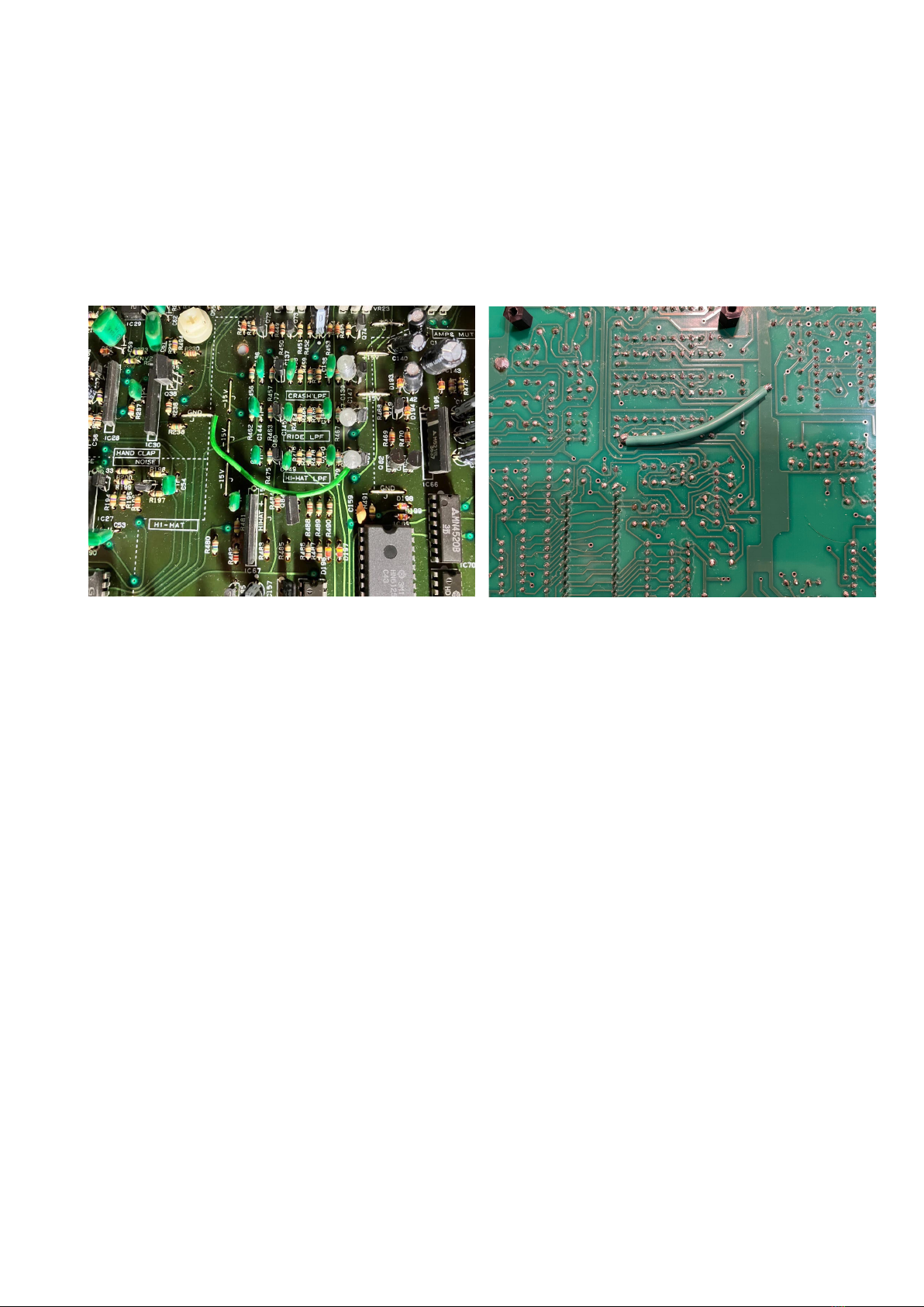
Hi, just wanted to share some good news about noise and crosstalk issues on RE-909. Pictured below is a Roland
TR-909 factory mod with a wire that seems to reinforce grounding between C151 styrofoam cap in the hihat low pass
filter and the common analog ground track where R236 is also attached. By doing the same mod in RE-909, pictured
below also in the bottom of the board, cymbals crosstalk and digital noise leak into the hihats channel is eliminated,
which fixes the last remaining issue in my build. I used a thick grounding wire to connect the lower pin of C151 to the
double hole in the common ground track next to R236. This fix works perfectly on traffo PSU but I can’t guarantee it
works on safe PSU (and preliminary tests show it doesn’t) because of the difference in ground routing. Otherwise, enjoy
your digital noise-free, crosstalk-free RE-909!!
2 - SD GAIN SCALING
Heads up for those who commented about their snare snappy being way too loud compared to the original. Some of us
worked together to look for a cause and we finally did find something. It took a bit to locate an original TR-909 to
analyse under the scope but once that was available it was easy to see.!
We followed the path of the noise signal in the snappy section of the snare in R286 right up to the Q47 and Q48 VCA
transistors and noticed it was exactly the same as the TR up until the voltage divider resistors R298 and R279 where
the signal was roughly doubled. We repeated this measurement across 3 RE-909 (first and second run) builds and one
(second run) which didn’t have this issue at all. We believe ground impedance could affect some builds, which in turn
could interfere in the voltage divider resistors. We measured 4Vpp noise (3V avg) in the snappy noise measurement
point (between C78 and R294) in RE-909 builds vs 1,70Vpp (1,2V avg) in a TR-909. Carter Goertzen used a
potentiometer to match the noise gain exactly to the TR and a solution was found by replacing R294 with a 1% 200K.
This value might be more or less universal if your snappy noise measurements match ours. We compared the output to
other 3 TR-909 samples and the result behaves like those and finally feels much better balanced.!
Another possible fix would be to play with R298 and R279 values and 1% resistors to counter impedance before the
VCAs and get the gain right but it doesn't seem as practical IMO.#
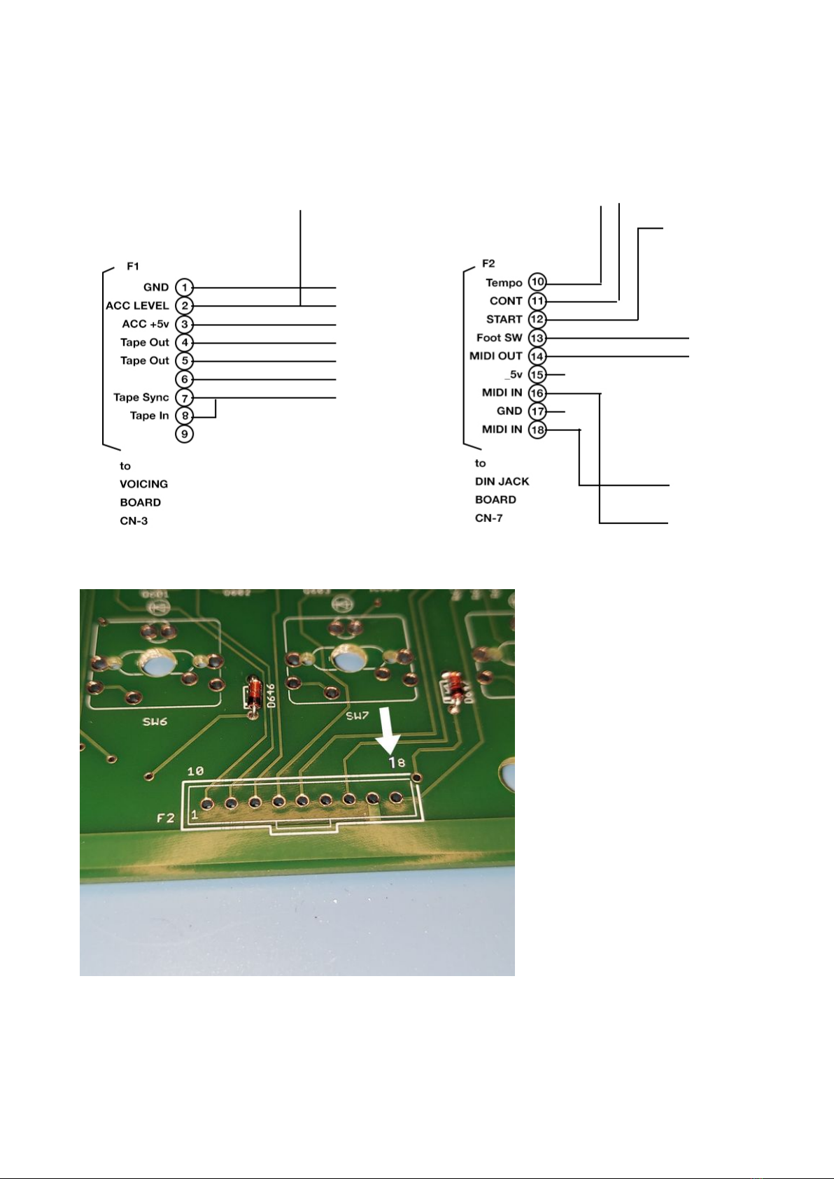
3 - SWITCHBOARD PCB ERROR
The pin numbers of the switchboard connectors were incorrect on the initial run. See the pin out/
destination diagram from the service notes (above) and be sure of your pins and destinations on
your switch board (below). Check twice, solder once.!

3A - RE-909 Cabling Guide
Switch Board F1 to Voicing Board CN3!
%1 — 29!
%2 — 28!
%3 — 27!
%4 — 26!
%5 — 25!
%6 — 24!
%7 — 23!
%8 — 22!
%9 — 21!
Switch Board F2 to DIN Jack Board CN7!
%10 — 10!
%11 — 11!
%12 — 12!
%13 — 13!
%14 — 14!
%15 — 15!
%16 — 16!
%17 — 17!
%18 — 18!
Switch Board F3 to Voicing Board CN1!
%19 — 1!
%20 — 2!
%21 — 3!
%22 — 4!
%23 — 5!
%24 — 6!
%25 — 7!
%26 — 8!
%27 — 9%| __ Disconnect for safety PSU!
%28 — 10 |!
Switch Board F4 to Voicing Board CN2!
%29 — 11!
%30 — 12!
%31 — 13!
%32 — 14!
%33 — 15!
%34 — 16!
%35 — 17!
%36 — 18!
%37 — 19!
%38 — 20!
Voicing Board W4 to DIN Jack Board CN4!
%30 — 30!
%31 — 31!
%32 — 32!
Voicing Board W5 to Multi Jack Board CN5!
%33 — 33!
%34 — 34!
%35 — 35!
%36 — 36!
%37 — 37!
%38 — 38!
%39 — 39!
%40 — 40!
%41 — 41!
%42 — 42!
Voicing Board W6 to Multi Jack Board CN6!
%43 — 43!
%44 — 44!
%45 — 45!
%46 — 46!
%47 — 47!
%48 — 48#
!
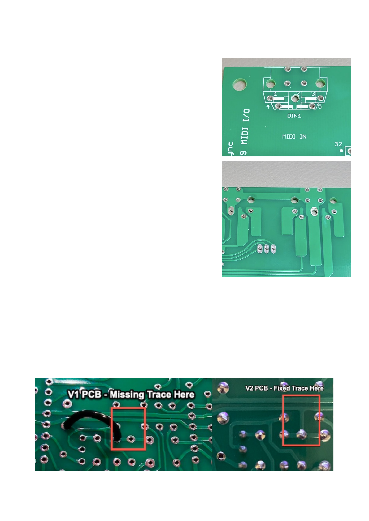
4 - MIDI IN PCB ERROR
We have noticed a small problem on the midi board, pin 2 from the midi
in port is connected to ground and under certain circumstances this can
lead to a buzz/hum when midi in is connected. Paul is going to update
the build docs, here are photos of two possible ways how to fix it (not
soldering pin 2 might be sufficient if it doesn't touch the pad):!
1. Use a dremel or round file to remove the pad/increase the diameter of
the hole to make sure pin 2 isn't connected to gnd or clip/remove !
pin 2 from the midi socket before soldering it!
2. if you have already built the midi board and don't want to desolder
the socket, cut a trace at 2 points and use a jumper to connect ground
to pin 17 of the connector!
SUGGESTED:
desolder the midi socket, lift (or cut) and isolate pin 2
and solder again.
5 - SD ENVELOPE FIX
RE-909 service advisory 15-12-20!
We found a minor error in the snare drum that didn't come up in testing. Its a simple fix with a single patch wire, please
download v.1.7 build documentation for details.!
Fixed in voice boards V2

6 - BATTERY TERMINALS
Affects all pcb versions, fix improves/solves memory retention issues.!
The battery terminal holes are missing the through hole plating, the fix is simple, please download V1.15 of the Build/
Bom guide for more details.!
7 - MATCHING TRANSISTORS
The following transistors MUST MATCH - The HFE readings should be exatly the same (ex: 290 hFe)!
Q6 (BD)!
Q12 (BD)!
Q19 (LT)!
Q20 (LT)!
Q21 (LT)!
Q26 (MT)!
Q27 (MT)!
Q28 (MT)!
Q33 (Noise)!
Q37 (CP)!
Q50 (SD)!
Q51 (SD)!
Q58 (HT)!
Q59 (HT)!
Q65 (RS)!
Q69 (HH/Cy)!
Q71 (HH/Cy)!
Q85 (HH/Cy)#
8 - SWITCHBOARD ELECTROLYTIC CAP GUIDANCE
Lay down all electrolytics under the switchboard (don’t place them standing up) !
There are clearance issues which present themselves intermittantly later, because the metal cap of an electrolytic
momentarily shorts a switchboard connection. this causes random crashes, stuck sequences, etcand it sucks. Lay
those caps flat.!

Table of contents
Other Din Sync Recording Equipment manuals


