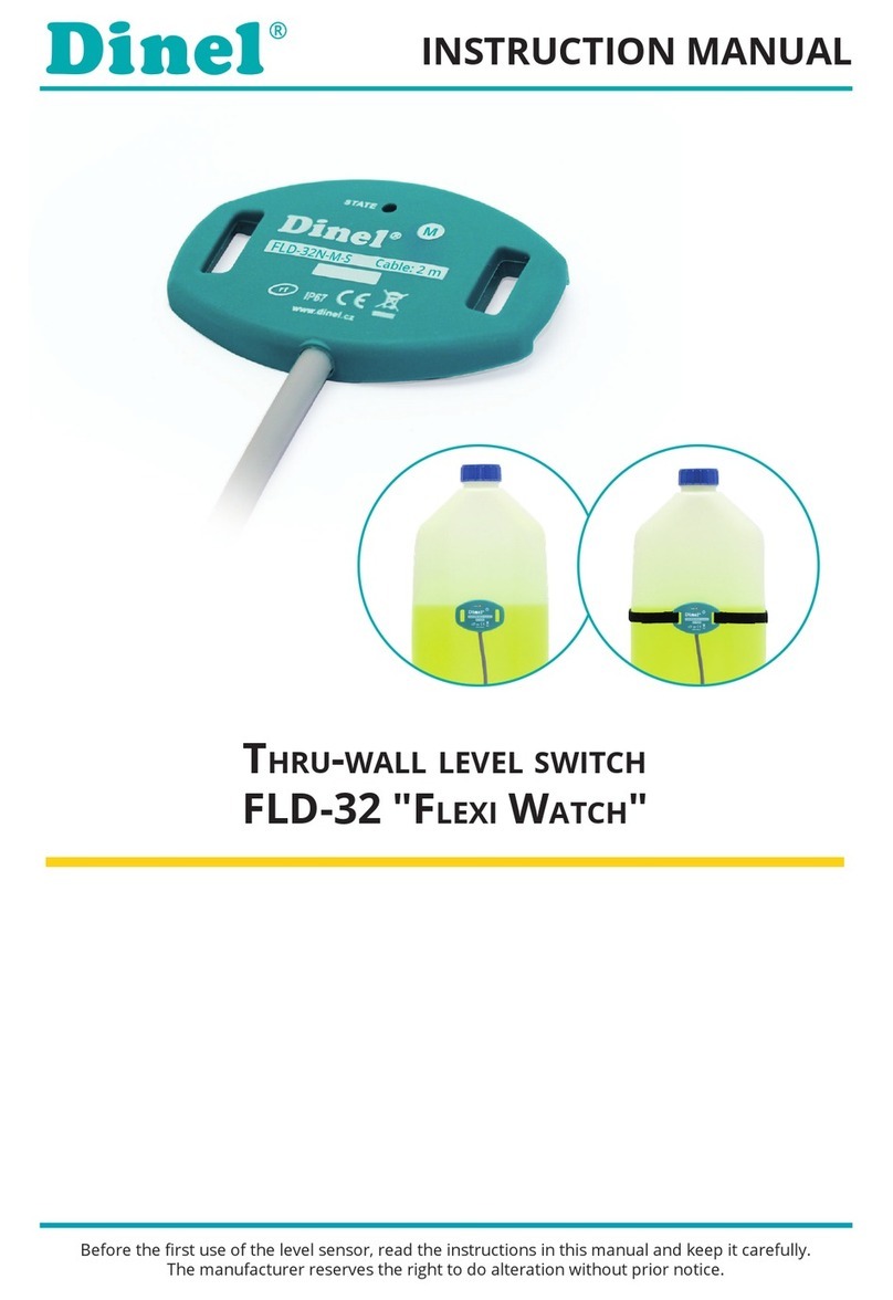
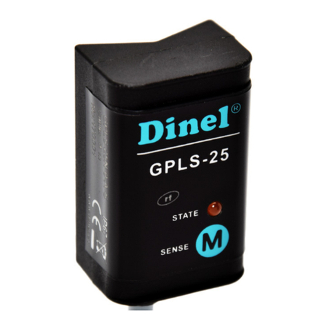
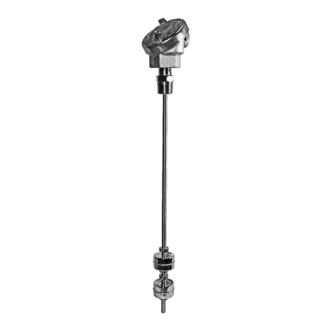
Dinel GPLS-25 Series User manual

Read carefully the instructions published in this manual before the fi rst use of the sensor. Keep the manual
at a safe place. The manufacturer reserves the right to implement changes without prior notice
INSTRUCTION MANUAL
industrial electronics
Thru-wall level swiTches GPls-25

CONTENTS
Product description......................................................................................................2
Features of variants.....................................................................................................2
Technicalspecications...............................................................................................2
Dimension drawings ....................................................................................................3
Recommended range of application ...........................................................................4
Unsuitable range of application...................................................................................4
Procedure for put sensor into operation ....................................................................4
1. Installation ...............................................................................................................4
2. Electrical connection................................................................................................5
3. Sensor settings........................................................................................................6
Status signalization......................................................................................................7
Order code...................................................................................................................8
Correctspecicationexamples....................................................................................8
Accessories .................................................................................................................8
Safety, protection and compatibility .............................................................................8

PrOduCT dESCriPTiON
Through wall level switches GPLS-25 are intended for liquid (conductive and non-
conductive) level detection on glass or plastic gauge-pipes, tubes and tanks. The
sensor is equipped with high frequency technology,which allows reliable operation
even for sensing of the adherent electrically conductive medium. The sensitivity and
modes (O - normally open or C - normally closed) of the switches can be easily set by
placing magnetic pen on sensitive spot. Output performance - transistor output with
open collector (PNP) or two wire electronic switch (S). This connection is done by
means of two wires directly into a circuit with relay or to binary input of control system.
2
FEaTurES OF variaNTS
TEChNiCal SPECiFiCaTiONS
Supply voltage 6 ... 30 V DC
Supply current – Output type P (OFF / ON state)
– Output type S (OFF state)
Max.0.6/7mA
Max.0.6mA
Switchingcurrent(Min./Max.)– Output type P (open collector PNP)
– Output type S (two wire el. switch)
100 mA
3.3 / 40 mA
Remanent voltage - ON state – Output type P (open collector PNP)
– Output type S (two wire el. switch)
1.8 V
6.0 V
Max.switchingfrequency 1Hz
Ambient temperature range –20 ... +80°C
Temperature range at the tube or vessel surface
Temperature range for using of double-side self adhesive tape
–20 ... +90°C
–20 ... +60°C
Max. thickness of the
vessel wall
– Conductive liquids
– Non.conductive liquids with Ɛr< 10*
8 mm
3 mm
Protection class IP 67
Housing material Plastic (PP)
Connection cable type (Variants „A“) – Output type P
– Output type S
PVC3x0.34mm2
PVC2x0.34mm2
Weight (including 2m cable) Approx.60g
*)Ɛr see “Table of dielectric constant“
• GPLS–25N–0 Prismatic (refracted) electrode, shape-adapted to be attached
tothegaugingpipeorothertube.Thexingofthesensorontoa
pipe is provided by plastic straps.
• GPLS–25N–1 Plannar electrode, suitableforinstallationonatsurfaces(e.g.
plasticorglasstanks).Thesensorcanbexedwithplasticstraps
or by double sided adhesive layer.

dimENSiON drawiNgS
GPLS–25N–0
GPLS–25N–1
Magnetic pen
MP–8
Variant"A"
with cable outlet
Variant "C"
with connector
cable
LED
Electrode
Sensitive spot
for setting
Detection of various types of liquids - water, disel, oil, cooling liquids, water solutions,
some types of solvents. It is suitable for glass or plastic gauge-pipes, vessels, plastic
container tanks, plastic tubs, pools, canisters, etc.
rECOmmENdEd raNgE OF aPPliCaTiON
3

4
The sensor also is not intended for level measurement on the gauge-pipe and the
container wall with antistatic treatment (partially electrically conductive).
uNSuiTablE raNgE OF aPPliCaTiON
1. iNSTallaTiON
The sensor is installed on a clean
and degreased surface of the ve-
ssel wall. The attachment is done
by doublesides adhesive layer.
Orientation of the sensor can be
arbitrary.Maximumthicknessofthe
vessel wall depends on the detec-
ted medium (see technical data),
themaximumis8mm.
The sensor is xed to the gauge
pipe or tube by means of two
plastic straps (2.5 mm width)
. The
cable should be vertically down-
wardsoriented.Themaximumwall
thickness of the tube depends on
the detected medium (see technical
data),themaximumis8mm.
Plastic straps
a) The sensor type GPLS–25N–0, which is intended to point level
detection on plastic or glass and gauge-tubes.
PrOCEdurE FOr PuT SENSOr iNTO OPEraTiON
b) The sensor type GPLS–25N–1, which is intended to thru-wall level
sensing of liquids in plastic or glass vessels with at walls.

2. ElECTriCal CONNECTiON
Positive pole (+U) of power supply is connected through a load (relay) to brown wire
or pin connector No. 1, negative pole is connected to while wire or pin connector No.3.
Note:
The sensor output is protected againts short circuits. Capacity loads and loads with low sleep resistance (bulb) the
sensor evaluation as a short circuit. In case of high ambient electromagnetic interference, parallel conductors with
power lines, or lines at distances greater than 30 m, we recommend to use shielded cable.
Connection scheme of sensor with “S“ type output
Positive pole (+U) of power supply is connected to brown wire or pin connector No.1,
negative pole is connected to blue wire or pin connector No.3. Load (relay) is connec-
ted to black wire or pin connector No.2.
Connection scheme of sensor with “PNP“ type output
Legend:
(1)...– Terminals number for variants with connector
BN – Brown
Electrical connection must be done in de-energized state!
For switching supply sources, it is necessary to check that the input is galvanically
separated from the network side and that they are tted with a lter suppressing the
conforming interference (terminals + and – oscillate together towards the ground
potential), or the interference is removed in another manner.
b) The type of sensor GPLS–25N–_-P
a) The type of sensor GPLS–25N–_-S
WH – White
BU – Blue
5

6
Sensitive spot
3. SENSOr SETTiNgS
The setting is done by placing of magnetic pen
MP-8 to sensitive spot Mlocated on the front of
the sensor. Short time attaching (up to 2 sec.)
of the magnetic pen to the sensitive spot Mmakes
the sensor open. Long attach (at least 4 sec.)
of the pen when the level is changed, denes
closed state of the sensor. In this way the sensiti-
vity for the measured medium and switching modes
“O“ (normally open) or “C“ (normally closed) is set.
Whenchangingtheuiditisnecessarytomake
the new setting.
a) Mode O (normally open)
Put the level of the measured medium in the state below the lower edge of the
sensor in the tank or in the gauge-pipe.
Attach the magnetic pen MP-8 to the sensitive spot Mfor maximum 2 seconds.
When the LED goes out, the sensor is in the state open.
After removal of the magnetic pen check the status of orange lights:
Put the level of the measured medium in the state above the upper edge of the
sensor in the tank or in the gauge-pipe.
Attach the magnetic pen MP-8 to the sensitive spot Mfor minimum 4 seconds.
When the LED lights up, the sensor is in the state closed.
After removal of the magnetic pen check the status of orange lights:
IftheLEDdoesn´tlightorisashingrapidly(0.2s),gotostep4.
IftheLEDlights,youmustrepeatstep2soasnottoexceedthelimitof2
seconds attaching magnetic pen.
If the LED lights, settings of the sensor is correct.
If the LED doesn´t light, the sensor was set incorrectly and you must repeat
the procedure from step 1.
I f t h e L E D i s a s h i n g , t h e s e n s o r d i d n ´ t r e c o g n i z e u p p e r a n d l o w e r l i m i t s .
Inthiscase,rstverifythatatthestep1thelevelofthemeasuredmedium
was below the lower edge of the sensor and at the step 3 the level of the
measured medium was above the upper edge of the sensor. Then make sure
thatthethicknessofthegauge-pipewallorthetankwalldoesnotexceed
thelimitspeciedintheTechnicalspecications(p.2).Ifnot,checkthere
isn´t a thick layer of sediment on the inner wall of the tank or the gauge-pipe.
1.
2.
3.
4.
5.
6.
-
-
-
-
-
For security reasons, we recommend to set the mode O (normally open, sensor closes
when immersed) for minimum level detection. Any failure of the sensor or wiring is equally
apparent as the emergency level state. Analogously – for the maximum level detection
is recommended to set the mode C (normally closed, sensor opens when immersed).

* Sensor with “S“ type output, for each ash of the LED switches its output on for approx. 3 ms. This period is
sufciently short to avoid unwanted switching of relay contacts. For binary inputs, we recommend to set the lter so
as not to respond to pulses shorter than 3 ms.
Indicator Function
Orange LED
Continuous light – Sensor is closed (switched ON)
Dark – Sensor is open (switched OFF)
Rapid ashing (period 0,2 sec.)*–
Unrecognized upper and lower limits of setting mistake
Slow ashing (period 0,8 sec.) – Short circuit at sensor output
STaTuS SigNalizaTiON
b) Mode C (normally closed)
7
Put the level of the measured medium in the state below the lower edge of the
sensor in the tank or in the gauge-pipe.
Attach the magnetic pen MP-8 to the sensitive spot Mfor minimum 4 seconds.
When the LED lights up, the sensor is in the state closed.
After removal of the magnetic pen check the status of orange lights:
Put the level of the measured medium in the state above the upper edge of the
sensor in the tank or in the gauge-pipe.
Attach the magnetic pen MP-8 to the sensitive spot Mfor maximum 2 seconds.
When the LED goes out, the sensor is in the state open.
After removal of the magnetic pen check the status of orange lights:
IftheLEDlightsorisashingrapidly(0.2s),gotostep4.
If the LED doesn´t light, you must repeat step 2 so as to observe the limit
of 4 seconds attaching magnetic pen.
If the LED doesn´t light, settings of the sensor is correct.
If the LED lights, the sensor was set incorrectly and you must repeat the
procedure from step 1.
I f t h e L E D i s a s h i n g , t h e s e n s o r d i d n ´ t r e c o g n i z e u p p e r a n d l o w e r l i m i t s .
Inthiscase,rstverifythatatthestep1thelevelofthemeasuredmedium
was below the lower edge of the sensor and at the step 3 the level of the
measured medium was above the upper edge of the sensor. Then make sure
thatthethicknessofthegauge-pipewallorthetankwalldoesnotexceed
thelimitspeciedintheTechnicalspecications(p.2).Ifnot,checkthere
isn´t a thick layer of sediment on the inner wall of the tank or the gauge-pipe.
1.
2.
3.
4.
5.
6.
-
-
-
-
-
After this settings the sensor responds to the level immersion and emersion in the
upper half of the sensing area and the hysteresis size 5 mm (1/8 of the distance
between the bottom and the top of the sensor).

Standard - included in the level sensors price Optional - for extra charge
• 2pcsofPlasticstraps2,5x200mm
• 1 pc of Double-side self adhesive tape (GPLS–25N–1)
• 1 pc of Magnetic pen MP–8
• Connector ELKA KV 3308
SaFETy, PrOTECTiONS aNd COmPaTibiliTy
The level sensor is equipped with a protection against electric shock on electrode,
polarity, overvoltage and short-term current overload on the output.
Electromagnetic compatibility is provided by conformity with standards
ČSNEN55022/B,ČSNEN61326-1,ČSNEN61000-4-2,ČSNEN61000-4-3,
ČSNEN61000-4-4,ČSNEN61000-4-6.
GPLS – 25N – – – cable
aCCESSOriES
Length of cable in meters (variant “A“)
A – cable outlet (+ Spec. the length of the cable)
C – connector
Electrode type: 0 – Prismatic (refracted)
1 – Planar
Electric connection:
P – PNP (open collector)
S – 2-wire electronic switch
Type of output:
COrrECT SPECiFiCaTiON ExamPlES
GPLS–25N–1–A–P cable 5 m
(1) planar electrode, (A)cableoutletwith5mlengthxedcable;(P) output type PNP.
GPLS–25N–0–C–S
(0) prismatic electrode, (C)electricconnectionwithconnector;(S) output type S (electronic switch).
OrdEr COdE
8

COrrECT SPECiFiCaTiON ExamPlES
GPLS–25N–1–A–P cable 5 m
(1) planar electrode, (A)cableoutletwith5mlengthxedcable;(P) output type PNP.
GPLS–25N–0–C–S
(0) prismatic electrode, (C)electricconnectionwithconnector;(S) output type S (electronic switch).
NOTE
9

NOTE
7 10

Dinel, s.r.o.
U Tescomy 249
760 01 Zlín
Czech Republic
Tel.: +420 577 002 003
Fax: +420 577 002 007
E-mail: [email protected]
www.dinel.cz
The lastest version of this instruction manual can be found at www.dinel.cz
Version:
industrial electronics
02/2017
Other manuals for GPLS-25 Series
1
This manual suits for next models
2
Table of contents
Other Dinel Switch manuals
Popular Switch manuals by other brands

SMC Networks
SMC Networks TigerSwitch SMC8124PL2 Specifications
Magnetrol
Magnetrol ECHOTEL 960 Installation and operating manual
Aiphone
Aiphone AX-248C Specifications

Allied Telesis
Allied Telesis AT-x510DP-52GTX installation guide
Hirschmann
Hirschmann MSM20 user manual
Shenzhen Kinan Technology
Shenzhen Kinan Technology CAT5 user manual
