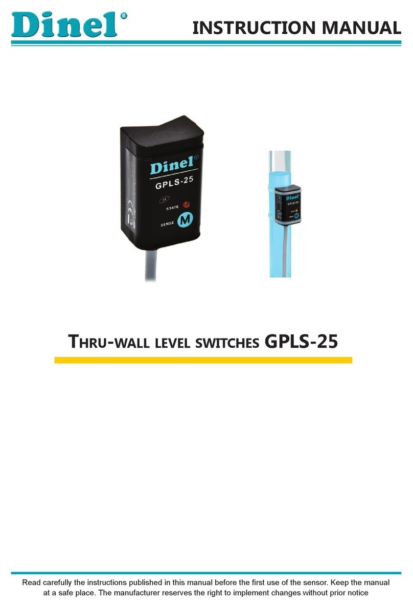
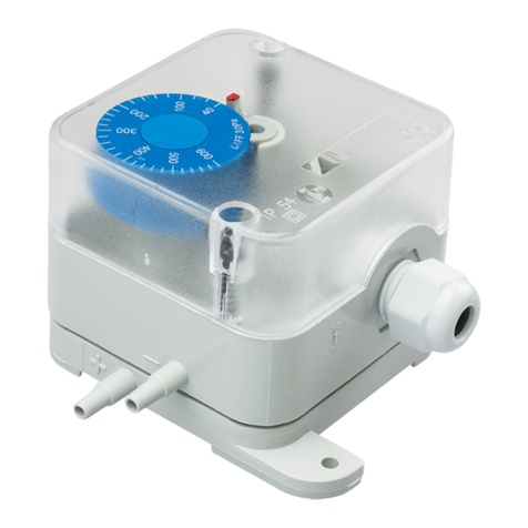
Dinel GPLS-25 Series User manual

Read carefully the instructions published in this manual before the rst use of the level meter. Keep the manual
at a safe place. The manufacturer reserves the right to implement changes without prior notice.
INSTRUCTION MANUAL
Thru-wall level switches GPLS-25

GPLS-25 © Dinel, s.r.o.
2
1. Basic description .......................................................................................................................3
2. Range of application ................................................................................................................3
3. Variants of sensors ...................................................................................................................4
4. Dimensional drawings .............................................................................................................4
5. Installation and putting into operation ............................................................................... 5
6. Mechanical mounting...............................................................................................................5
7. Electrical connection ................................................................................................................ 7
8. Setting ..........................................................................................................................................7
9. Status signalization .................................................................................................................. 8
10. Order code................................................................................................................................... 9
11. Correctspecicationexamples..............................................................................................9
12. Accessories .................................................................................................................................9
13. Safety, protection and compatibility ...................................................................................9
14. Use, operation and maintenance ........................................................................................10
15. General warranty conditions................................................................................................10
16. Marking of labels .....................................................................................................................11
17. Technicalspecications ........................................................................................................12
18. Packing, shipping and storage..............................................................................................12
Contents

3
© Dinel, s.r.o. GPLS-25
Through wall level switches GPLS-25 are intended for liquid (conductive and non-conductive)
level detection on glass or plastic gauge-pipes, tubes and tanks. The sensor is equipped with high
frequency technology,which allows reliable operation even for sensing of the adherent electrically
conductive medium. The sensitivity and modes (O - normally open or C - normally closed) of the
switches can be easily set by placing magnetic pen on sensitive spot. Output performance - transistor
output with open collector (PNP) or two wire electronic switch (S). This connection is done by means
of two wires directly into a circuit with relay or to binary input of control system.
1. Basic description
To ensure maximum safety of control processes, we have dened the following safety instructions
and information. Each instruction is labelled with the appropriate pictogram.
Alert, warning, danger
This symbol informs you about particularly important instructions for installation and operation of
equipment or dangerous situations that may occur during the installation and operation. Not observing
these instructions may cause disturbance, damage or destruction of equipment or may cause injury.
Information
This symbol indicates particularly important characteristics of the device.
Note
This symbol indicates helpful additional information.
Used symbols
Safety
All operations described in this instruction manual have to be carried out by trained personnel
or by an accredited person only. Warranty and post warranty service must be exclusively
carried out by the manufacturer.
Improper use, installation or set-up of the sensor can lead to crashes in the application.
The manufacturer is not responsible for improper use, loss of work caused by either direct
or indirect damage, and for expenses incurred at the time of installation or during the period
of use of the level sensors.
2. Range of application
Detection of various types of liquids - water, disel, oil, cooling liquids, water solutions, some types
of solvents. It is suitable for glass or plastic gauge-pipes, vessels, plastic container tanks, plastic
tubs, pools, canisters, etc.

GPLS-25 © Dinel, s.r.o.
4
3. Variants of sensors
VARIANTS
code electrode description
GPLS–25N–0
Prismatic
(refracted)
electrode
Shape-adapted to be attached to the gauging pipe or other tube. The
xing of the sensor onto a pipe is provided by plastic straps.
GPLS–25N–1 Plannar
electrode
Suitable for installation on at surfaces (e.g. plastic or glass tanks). The
sensor can be xed with plastic straps or by double sided adhesive layer.
4. Dimensional drawings
GPLS–25N–0
GPLS–25N–1
Magnetic pen MP–8
Variant“A“
with cable outlet
Variant „C“
with connector
cable
LED
Electrode
Sensitive spot
for setting

5
© Dinel, s.r.o. GPLS-25
4
5. Installation and putting into operation
Please follow next 4 steps:
• Mechanical mounting - see chapter 5
• Electrical connection - see chapter 7
• Settings - see chapter 8
6. Mechanical mounting
THE SENSOR TYPE GPLS–25N–0
• is intended to point level detection on plastic or
glass and gauge-tubes.
• The sensor is xed to the gauge pipe or tube by
means of two plastic straps (2.5 mm width). The
cable should be vertically downwards oriented.
The maximum wall thickness of the tube depends
on the detected medium (see technical data), the
maximum is 8 mm.
Plastic straps
THE SENSOR TYPE GPLS–25N–1
• is intended to thru-wall level sensing of liquids in
plastic or glass vessels with at walls.
• The sensor is installed on a clean and degreased
surface of the vessel wall. The attachment is done
by doublesides adhesive layer. Orientation of the
sensor can be arbitrary. Maximum thickness of
the vessel wall depends on the detected medium
(see technical data), the maximum is 8 mm.

GPLS-25 © Dinel, s.r.o.
6
7 . Electrical connection
THE TYPE OF SENSOR GPLS–25N–_-S
Positive pole (+U) of power supply is connected through a load (relay) to brown wire or pin
connector No. 1, negative pole is connected to while wire or pin connector No.3.
THE TYPE OF SENSOR GPLS–25N–_-P
Positive pole (+U) of power supply is connected to brown wire or pin connector No.1, negative
pole is connected to blue wire or pin connector No.3. Load (relay) is connected to black wire or
pin connector No.2.
Connection scheme of sensor
with “S“ type output
Connection scheme of sensor
with “PNP“ type output
Legend:
(1) – Terminals number for variants with connector
BN – Brown
WH – White
BU – Blue
The sensor GPLS-28 output is protected againts short circuits. Capacity loads and loads with
low sleep resistance (bulb) the sensor evaluation as a short circuit. In case of high ambient
electromagnetic interference, parallel conductors with power lines, or lines at distances greater than
30 m, we recommend to use shielded cable.
Electrical connection must be done in de-energized state!
For switching supply sources, it is necessary to check that the input is galvanically separated
from the network side and that they are tted with a lter suppressing the conforming
interference (terminals + and – oscillate together towards the ground potential), or the
interference is removed in another manner.

7
© Dinel, s.r.o. GPLS-25
8 . Setting
a) Mode O (normally open)
1. Put the level of the measured medium in the state below the lower edge of the sensor in the
tank or in the gauge-pipe.
2. Attach the magnetic pen MP-8 to the sensitive spot Mfor maximum 2 seconds. When the
LED goes out, the sensor is in the state open.
3. After removal of the magnetic pen check the status of orange lights:
- f the LED doesn´t light or is ashing rapidly (0.2 s), go to step 4.
- If the LED lights, you must repeat step 2 so as not to exceed the limit of 2 seconds attaching
magnetic pen.
4. Put the level of the measured medium in the state above the upper edge of the sensor in the
tank or in the gauge-pipe.
5. Attach the magnetic pen MP-8 to the sensitive spot Mfor minimum 4 seconds. When the
LED lights up, the sensor is in the state closed.
6. After removal of the magnetic pen check the status of orange lights:
- If the LED lights, settings of the sensor is correct.
- If the LED doesn´t light, the sensor was set incorrectly and you must repeat the procedure
from step 1.
- If the LED is ashing, the sensor didn´t recognize upper and lower limits. In this case, rst
verify that at the step 1 the level of the measured medium was below the lower edge of the
sensor and at the step 3 the level of the measured medium was above the upper edge of
the sensor. Then make sure that the thickness of the gauge-pipe wall or the tank wall does
not exceed the limit specied in the Technical specications (p. 2). If not, check there isn´t
a thick layer of sediment on the inner wall of the tank or the gauge-pipe.
For security reasons, we recommend to set the mode O (normally open, sensor closes when
immersed) for minimum level detection. Any failure of the sensor or wiring is equally apparent as
the emergency level state. Analogously – for the maximum level detection is recommended to set
the mode C (normally closed, sensor opens when immersed).
Sensitive
spot
The setting is done by placing of magnetic pen MP-8 to
sensitive spot Mlocated on the front of the sensor. Short
time attaching (up to 2 sec.) of the magnetic pen to the
sensitive spot Mmakes the sensor open. Long attach (at
least 4 sec.) of the pen when the level is changed, denes
closed state of the sensor. In this way the sensitivity for
the measured medium and switching modes “O“ (normally
open) or “C“ (normally closed) is set. When changing the
uid it is necessary to make the new setting.

GPLS-25 © Dinel, s.r.o.
8
Indicator Function
Orange
LED
Continuous light – Sensor is closed (switched ON)
Dark – Sensor is open (switched OFF)
Rapid ashing (period 0,2 sec.) *
– Unrecognized upper and lower limits of setting mistake
Slow ashing (period 0,8 sec.) – Short circuit at sensor output
9 . Status signalization
* Sensor with “S“ type output, for each ash of the LED switches its output on for approx. 3 ms. This period is sufci-
ently short to avoid unwanted switching of relay contacts. For binary inputs, we recommend to set the lter so as not
to respond to pulses shorter than 3 ms.
b) Mode C (normally closed)
1. Put the level of the measured medium in the state below the lower edge of the sensor in the
tank or in the gauge-pipe.
2. Attach the magnetic pen MP-8 to the sensitive spot Mfor minimum 4 seconds. When the
LED lights up, the sensor is in the state closed.
3. After removal of the magnetic pen check the status of orange lights:
- If the LED lights or is ashing rapidly (0.2 s), go to step 4.
- If the LED doesn´t light, you must repeat step 2 so as to observe the limit of 4 seconds
attaching magnetic pen.
4. Put the level of the measured medium in the state above the upper edge of the sensor in the
tank or in the gauge-pipe.
5. Attach the magnetic pen MP-8 to the sensitive spot Mfor maximum 2 seconds. When the
LED goes out, the sensor is in the state open.
6. After removal of the magnetic pen check the status of orange lights:
- If the LED doesn´t light, settings of the sensor is correct.
- If the LED lights, the sensor was set incorrectly and you must repeat the procedure from
step 1.
- If the LED is ashing, the sensor didn´t recognize upper and lower limits. In this case, rst
verify that at the step 1 the level of the measured medium was below the lower edge of the
sensor and at the step 3 the level of the measured medium was above the upper edge of
the sensor. Then make sure that the thickness of the gauge-pipe wall or the tank wall does
not exceed the limit specied in the Technical specications (p. 2). If not, check there isn´t
a thick layer of sediment on the inner wall of the tank or the gauge-pipe.
After this settings the sensor responds to the level immersion and emersion in the upper half of
the sensing area and the hysteresis size 5 mm (1/8 of the distance between the bottom and the
top of the sensor).

9
© Dinel, s.r.o. GPLS-25
GPLS–25N–1–A–P cable 5 m
(1) planar electrode, (A) cable outlet with 5 m length xed cable; (P) output type PNP.
GPLS–25N–0–C–S
(0) prismatic electrode, (C) electric connection with connector; (S) output type S (electronic switch).
10 . Order code
11 . Correct specification examples
GPLS – 25N – – – cable Length of cable in meters (variant “A“)
A– cable outlet (+ Spec. the length of the cable)
C– connector (socket not included in the sensor,
see accessories for recommended type)
Electrode
type:
0– Prismatic (refracted)
1– Planar
Electric
connection:
P– PNP (open collector)
S– 2-wire electronic switch
Type of
output:
12 . Accessories
13 . Safety, protection and compatibility
The level sensor is equipped with a protection against electric shock on electrode, polarity, over-
voltage and short-term current overload on the output.
Protection against dangerous contact is ensured by supplying safe voltage according to ČSN 33
2000-4-41 (SELV).
Electromagnetic compatibility is provided by conformity with standards EN 55011(B), EN 61326-1,
EN 61000-4-2 (A, 8 kV), EN 61000-4-3 (A, 10 V), EN 61000-4-4 (A, 2 kV), EN 61000-4-5 (B, 1
kV), EN 61000-4-6 (A, 3 V) and EN 61000-4-8 (A, 30 A).
This equipment has been issued a declaration of conformity in accordance with Act 90/2016 Coll.
and subsequent amendments. The delivered electrical equipment meets the requirements of the
applicable government regulations on safety and electromagnetic compatibility.
Standard - included in the level sensors price Optional - for extra charge
• 2 pcs of Plastic straps 2,5 x 200 mm
• 1 pc of Double-side self adhesive tape
(GPLS–25N–1)
• 1 pc of Magnetic pen MP–8
• Connector ELKA KV 3308

GPLS-25 © Dinel, s.r.o.
10
14 . Use, operation and maintenance
15 . General warranty conditions
The manufacturer warrants from the date of delivery that this product will have the specied char-
acteristics as stated in the technical specications for a period of 3 years.
The manufacturer is liable for defects found during the warranty period and claimed in writing.
The warranty does not cover defects caused by improper handling or failure to comply with the
technical specications.
The warranty is void if the customer or a third party makes changes or modications to the product,
if the product is mechanically or chemically damaged, or if the serial number is illegible.
To make a claim, the warranty certicate must be presented.
In the event of a legitimate claim, we will repair or replace the defective product. In both cases, the
warranty period will be extended by the repair period.
The sensor requires no operator to operate. During operation,the operator of the technological unit is
informed about the level of the measured substance in the status gauge by an LED signalling diode.
The maintenance of the device consists in regular checking of the cable integrity and removal of
dirt from the back side of the sensor. It is forbidden to make any changes to the device without the
manufacturer‘s consent. Any repairs must be carried out only by the manufacturer of the device
or by a service organisation authorised by him.
Installation, operation and maintenance of the equipment must be carried out in accordance with
these technical conditions and the provisions of the applicable standards must be observed.

11
© Dinel, s.r.o. GPLS-25
Data on the plate of the unit of
16 . Marking of labels
GPLS-25
Dinel
STATE
SENSE
U = 6 ... 30 V
t = -20 ... +80°C
a
I = 100 mA
o max
IP67
GPLS-25N-0-A-P
No:170001
M
Cable: 2 m
www.dinel.cz
BN
BU
BK
+U
0V
ŠtítekproGPLS-25N-x-x-P
BN
WH (BU)
+U
0V
GPLS-25
Dinel
STATE
SENSE
U = 6 ... 30 V
t = -20 ... +80°C
a
I = 40 mA
max
IP67
M
www.dinel.cz
ŠtítekproGPLS-25N-x-x-S
GPLS-25N-0-A-S
No:170001
Cable: 2 m
rf
rf
GPLS-25N-x-x-P GPLS-25N-x-x-S
GPLS-25
Dinel
STATE
SENSE
U = 6 ... 30 V
t = -20 ... +80°C
a
I = 100 mA
o max
IP67
GPLS-25N-0-A-P
No:170001
M
Cable: 2 m
www.dinel.cz
BN
BU
BK
+U
0V
ŠtítekproGPLS-25N-x-x-P
BN
WH (BU)
+U
0V
GPLS-25
Dinel
STATE
SENSE
U = 6 ... 30 V
t = -20 ... +80°C
a
I = 40 mA
max
IP67
M
www.dinel.cz
ŠtítekproGPLS-25N-x-x-S
GPLS-25N-0-A-S
No:170001
Cable: 2 m
rf
rf
Symbol of producer: logo Dinel®
Internet address: www.dinel.cz
Type of level meter: GPLS–25N-_-_-_
Cable length: (only for GPLS-25N-_-A-_)
Product serial number: Ser. No.: xxxxx – (from left: year of manufacture, serial production No.)
Supply voltage range: U=6...30 VDC
Output current range: IMAX , nebo IOMAX
Ambient temperature range: ta= -20 ...+80 °C
protection: IP67
mark of conformity:
mark for take-back of electrical waste:

GPLS-25 © Dinel, s.r.o.
12
17. Technical specifications
Technical specifications
Supply voltage 6 ... 30 V DC
Supply current – Output type P
– Output type S
max. 0,6 / 7 mA
max. 0,6 mA
Switched current (Min. / Max.) – Output type P
– Output type S
100 mA
3,3 / 40 mA
Remanent voltage – ON state – Output type P
– Output type S
1,8 V
6,0 V
Switching frequency 1 Hz
Ambient temperature range –20 ... +80°C
Temperature range at the tube or vessel surface / with double-side self adhesive tape –20 ... +90°C/+60°C
Max. thickness of the vessel wall – Conductive liquids
– Non-conductive liquids with ɛr< 10*
8 mm
3 mm
Protection class IP 67
Housing material plastic (PP)
Connection cable type (Variants “A”) – Output type P
– Output type S
PVC 3 x 0,34 mm2
PVC 2 x 0,34 mm2
Weight (including 2 m cable) Approx 60 g
*) ɛrsee “Table of dielectric constants”
18 . Packing, shipping and storage
The GPLS-25 is packed in a polythene bag and the entire shipment is placed in a cardboard box.
Suitable padding is used in the cardboard box to prevent mechanical damage in transit.
Remove the equipment from the packaging before using it to prevent possible damage.
Transportation to the customer is carried out by a freight forwarding company. By prior arrange-
ment, personal collection of the ordered goods at the company‘s headquarters is also possible.
Upon receipt, please check whether the shipment is complete and corresponds to the scope of
the order, or whether the packaging and equipment have been damaged during transport. Do not
use equipment obviously damaged in transit, but contact the manufacturer to resolve the situation.
If the equipment is to be transported, it must be packed in its original packaging and protected
against shocks and weathering.
Store the equipment in its original packaging in a dry area, sheltered from the weather, with humidity
up to 85% without the eects of chemically active substances. The storage temperature range is
-10 °C to +50 °C.

13
© Dinel, s.r.o. GPLS-25

Dinel, s.r.o.
U Tescomy 249
760 01 Zlín
Czech Republic
phone: +420 577 002 003
email: sale@dinel.cz
www.dinel.cz
The current version of the manual can be found on www.dinel.cz
Version: 04/2021
industrial electronics
Other manuals for GPLS-25 Series
1
This manual suits for next models
2
Table of contents
Other Dinel Switch manuals
