Dinel CPS-24 User manual

Read carefully the instructions published in this manual before the rst use of the level meter. Keep the manual
at a safe place. The manufacturer reserves the right to implement changes without prior notice.
průmyslová elektronika

1 . Basic description ........................................................................................................................4
2 . Dimensional drawing ...................................................................................................................5
3 . Installation and putting into operation .........................................................................................5
4 . Installation instructions ................................................................................................................6
5 . Electrical connection ...................................................................................................................7
6 . Settings .......................................................................................................................................8
7 . Function and status indication .....................................................................................................9
8 . Order code ..................................................................................................................................9
9 . Correct specication examples ...................................................................................................9
10 . Accessories .............................................................................................................................10
11. Safety, protections, compatibility a explosion proof.................................................................10
12 . Use, manipulation and maintenance .......................................................................................10
13 . General, conditions and warranty ...........................................................................................11
14 . Marking of labels .....................................................................................................................11
15. Specications ..........................................................................................................................13
16 . Packings, shipping and storage ..............................................................................................14
CPS–24 © Dinel, s.r.o.
3
Capacitive proximity switch CPS–24 is intended for detection of proximity or motion of solid
objects. It is suitable for indication of the liquid level through non-conductive walls of vessels or on
non-conductive gauge-pipes. It is excellent for liquid leakage detection in collection pits or directly
on oors. The sensor state is indicated by LED. The sensitivity is adjustable by a trimmer located
under a cover screw on the rear side. The design and housing materials of CPS allow the use in
complicated environments (harsh, dusty, explosive, aggressive) as well as in clean environments
(medical technology).
To ensure maximum safety of control processes, we have dened the following safety instructions
and information. Each instruction is labelled with the appropriate pictogram.
This symbol informs you about particularly important instructions for installation and operation of
equipment or dangerous situations that may occur during the installation and operation. Not observing
these instructions may cause disturbance, damage or destruction of equipment or may cause injury.
This symbol indicates particularly important characteristics of the device.
This symbol indicates helpful additional information.
Alloperations described inthis instruction manualhave to becarried out bytrained personnel
or by an accredited person only. Warranty and post warranty service must be exclusively
carried out by the manufacturer.
Improper use, installation or set-up of the sensor can lead to crashes in the application.
The manufacturer is not responsible for improper use, loss of work caused by either direct
or indirect damage, and for expenses incurred at the time of installation or during the period
of use of the level sensors.

4
© Dinel, s.r.o. CPS–24
Variant "A" with
short cable outlet
Please follow next 3 steps:
Variant "B" with
long cable outlet
Variant "C" with
connector
Inthecaseoftheuseforanaggressivemediumis necessary to prove the chemical compatibility
of used materials of the sensor (Tab. Used materials on page 13). This guarantee ceases
when the product is chemically damaged.

CPS–24 © Dinel, s.r.o.
5
Sensing of bulky-solid materials in metal con-
tainers or tanks. The position of the sensor is
set so that it is approximately 10 mm from the
inner wall of a storage tank.
Sensor is used for sensing leakages in an
interception tank. Leakage indication in de-
tention pits and boxes with “Plate holder
PD–24–1”.
PD–24–1
Fixing plastic strap
PD–24–1
Sensor application for level gauges and eye
sights. The maximum wall thickness in both
cases is up to 10 mm. A glass or plastic level
gauge (tube) must have an outer diameter of
at least 20 mm. The face of the sensor must
be touching the wall.
Sensing of moving objects on conveyor. The
distance of the sensor from moving objects is
set according to their size, shape and material
composition (approx. 1 to 8 mm).
Detection of liquid presence in the inter-wall space of double-walled storage tanks. The sensor is
suspended down into the inter-wall space on its own cable. For this application, we recommend
variant „B“ with an extended cable terminal with the installation variant of a PVC hose for cable
protection.
Distance crown DK–24
Intrinsically safe supply units
(NSSU, NDSU or NLCU)
Fig. 1: Sensing bulk-solid materials in storage tanks Fig. 2: Use of CPS for sensing leakages in an
interception tank
Fig. 3: Sensing objects on a conveyor Fig. 4: CPS sensor application for level gauges and
eye sights
Fig. 5: Use of CPS for indicating presence of liquid in the inter-wall space

6
© Dinel, s.r.o. CPS–24
In the case of vertical mounting in outer areas or in the
case of high mechanical exertion we recommend to in-
stall in Variant “B” protective hose on the cable (see
gure).
Protective hose
Cable
Hose clip
Fig. 6: protective PVC hose
Sensor with NPN or PNP output is allowed to lead only by resistive or inductive lead. Positive sup-
ply voltage (+U) is connected to the brown conductor BN (1), negative (0 V) to the blue conductor
BU (3) and the leads (only NPN or PNP type of output) to the black conductor BK (4). The capacity
loads and low resistance loads (bulb) is evaluated by the sensor as short circuit.
The line from CPS-24N to the connecting device is from a suitable three wire (min. 3x0.5 mm2)
cable, in the case of variant CPS-24Xi using a two wire (min. 2x0.5 mm2) cable. In the event that
a disassemblable socket ELWIKA or ELKA 4012 K PG7 are used, the max. outer diameter of the
cable is 6 mm. Connector socket is not part of the sensor.
Fig. 7: NPN type sensors connection
(version “N”)
Fig. 8: NAMUR type sensors connection
(version “Xi”)
Fig. 9: PNP type sensors connection
(version “P”)
Output (BK)
0V (BU)
+U (BN)
Fig. 10: Inside of the connector socket
Legend:
(*) – Numbers of terminals inside of the connector
BK – Black
BN – Brown
BU – Blue
Electrical connection can only be made when de-energized!
The source of the power voltage must comprise of a stabilised safe low power source with
galvanic separation. In the event that a switch-mode power supply is used, it is essential
that its construction effectively suppresses common mode interference on the secondary
side. In the event that the switch-mode power supply is equipped with a PE safety terminal,
it must be unconditionally grounded! Spark-safe devices (type CPS-24) must be powered
from a spark-safe power source meeting the above-mentioned requirements.

CPS–24 © Dinel, s.r.o.
7
Due to the possible occurrence of an electrostatic charge on the non-conductive parts of
the sensor, it is necessary to ground all sensors intended for use in environments with an
explosion hazard (type CPS-24Xi). This can be performed by grounding el. conductive tanks
or el. conductive tank lids, and in the case of el. non-conductive tanks using and grounding
an auxiliary plate electrode PDE-27.
In the event that the water level meter (sensor) is installed in an outdoor environment at a
distance greater than 20 m from the outdoor switchboard, or from an enclosed building, it
is necessary to supplement the electrical cable leading to the water level meter (sensor)
with suitable overvoltage protection.
In the event of strong ambient electromagnetic interference, paralleling of conductors with
power distribution, or for distribution to distances over 30 m, we recommend using a shielded
cable and grounding the shielding on the side of the power source.
The sensitivity is set by trimmer located under cover screw on the rear side. Clockwise turning
makes the sensitivity lower, reverse direction turning makes the sensitivity higher.
LED
Sensitivity
Cable outlet
or connector
Fig. 11: Top view of level sensor
SETTING THE BASE SENSITIVITY:
a) Type CPS-24_-_-_O:
Turn the trimmer to the left until the LED is lit. Then turn slightly to the right until the LED just
turns o. From this point, turn 180° to the right.
b) Type CPS-24_-_-_C:
Turn the trimmer to the left until the LED turns o. Then turn slightly to the right until the LED is
lit. From this point, turn 180° to the right.
After setting the sensitivity, do not forget to properly tighten the trimmer cover screw.
The base sensitivity of the sensor is factory set (sensing distance on the metal surface) 8 mm. The
actual sensitivity (sensing distance) depends on the dielectric properties or where appropriate the
conductivity of the sensed material.
For sensing of materials with a low relative permittivity (plastics), we recommend to individually set
a higher sensitivity, or consult with the manufacturer if necessary.

8
© Dinel, s.r.o. CPS–24
Level state Type of output Output state LED indication
Minimum level sensing
CPS–24N– _ –NO
CPS–24N– _ –PO CLOSED
(Shine)
CPS–24Xi –_ –RO HIGHER
CURRENT
CPS–24N– _ –NO
CPS–24N– _ –PO OPEN
(Dark)
CPS–24Xi –_ –RO LOWER
CURRENT
Maximum level sensing
CPS–24N– _ –NC
CPS–24N– _ –PC CLOSED
(Shine)
CPS–24Xi –_ –RC HIGHER
CURRENT
CPS–24N– _ –NC
CPS–24N– _ –PC OPEN
(Dark)
CPS–24Xi –_ –RC LOWER
CURRENT
For minimum level sens-
ing we recommend sen-
sor with normally open
output (NO, PO, RO). It is
for failure safety reasons
– eventual failure of sen-
sor behaves similarly as
an exceeding of the limit
state.
Analogically for maximum
level sensing we recom-
mend normally closed out-
puts (NC, PC, RC).
For leakage indication
we recommend the NC,
PC, RC version too. It is
maximum level sensing
as well, despite the sen-
sor is at the lowest place
in the room.
CPS – 24 – –
Mech. performace:
N – non-explosive areas
Xi – for explosive environmentsr
Output state at non-activated electrode: O – Open (NAMUR – Lower current)
C – Closed (NAMUR – Higher current)
Type of output: N – NPN (Open collector)
P – PNP (Open collector)
R – NAMUR
Electric connection:
A – Short cable outlet (+ Spec. the length of the cable)
B – Long cable outlet (+ Spec. the length of the cable)
C – Connector (+ Spec. type of the socket)
CPS–24N–A–PC cable 4 m
(N) Performance for non-explosive areas; (A) Short cable outlet with 4 m cable length; (PC) Output type PNP with
closed state at non-activated electrode
CPS–24Xi–B–RO cable 7 m
(Xi) Explosion-proof performance; (B) Long cable outlet with 7 m cable length; (RO) Output type NAMUR with
lower current at non-activated electrode
CPS–24N–C–NO cable 7 m
(N) Performance for non-explosive areas; (C) Connector; (NO) Output type NPN with open state at non-activated
electrode

CPS–24 © Dinel, s.r.o.
9
optional – for a surcharge
(see catalogue sheet of accessories)
• Extra cables over the standard length 2 m
(for electric connection type “A” or “B”)
• Connector plug (type ELWIKA or ELKA)
• Plate holder PD–24–1
• Distance crown DK–24
standard – included in the level sensor price
• 2 pcs. of stainless steel xing nuts
• 1 pcs. Screwdriver for adjustment (each
5 pcs.)
The level sensor is equipped with protection against electric shock on the electrode, reverse polar-
ity, output current overload, short circuit and against current overload on output.
Protection against dangerous contact is provided by low safety voltage according to EN 33 2000-4-
41. Electromagnetic compatibility is provided by conformity with standards EN 55 022/B, EN 61326-
1/Z1, EN 61000-4-2, EN 61000-4-3, EN 61000-4-4, EN 61000-4-6.
Explosion proof CPS-24Xi is provided by conformity with standards EN 60079-0:2013, EN 60079-
11:2012.
Explosion proof CPS-24Xi is veried FTZÚ – AO 210 Ostrava – Radvanice: FTZÚ 02 ATEX 0233X
A declaration of conformity was issued for this device in the wording of Act No. 90/2016 Coll., as
amended. Supplied electrical equipment matches the requirements of valid European directives for
safety and electromagnetic compatibility.
The level sensor is designed to be connected with supply unit type NSSU, NDSU and NLCU.
If some other approved apparatus is used, its output parameters comply with above mentioned
parameters, then it is necessary to include galvanic separation and/or in case of application of ap-
paratus without galvanic separation (Zener safety barriers) it is necessary to provide equipotential
equalisation between sensor and point of barrier earthing.
For zone 0 application the present potentially explosive atmosphere of air mixture with gases, mists
or vapours shall comply the following:
Tamb = -20 to +60°C, p = 0.8 bar to 1.1 bar.
Maximum input parameters:
Ui = 12 V; Ii = 15 mA; Pi = 45 mW; Ci = 15 nF; Li = 10 µH
10
© Dinel, s.r.o. CPS–24
Detection of approach or assessment of the movement of solid objects, level indication in electri-
cally non-conductive storage tanks (plastic, glass) and level gauges. Limit sensing of non-abrasive
bulk-solid materials (cereals, grains, granulates, sand, etc.) in metal storage tanks. Detection of the
presence of liquids in the inter-wall area of double-walled storage tanks, liquid leakage detection in
interception traps, concrete sumps or directly on the oor.
Dinel, s.r.o. guarantees for the period of three (3) years that the product has the characteristics as
mentioned in the technical specication.
Dinel, s.r.o. is liable for defects ascertained within the warranty period and were claimed in writing.
This guarantee does not cover the damages resulting from misuse, improper installation or incorrect
maintenance.
This guarantee ceases when the user or the other person makes any changes on the product or the
product is mechanically or chemically damaged, or the serial number is not readable.
The warranty certicate must be presented to exercise a claim.
In the case of a rightful complaint, we will replace the product or its defective part. In both cases, the
warranty period is extended by the period of repair.
We do not recommend using for the measurement of el. conductive liquids that leave a
continuous lm on the inner wall of an el. non-conductive storage tank or level gauge and
liquids that exude el. conductive particles that deposit themselves on the wall of a storage
tank or level gauge (e.g. heavily mineralised water, chemically treated waste water). Likewise,
the sensor is also not intended for measuring levels on level gauges and walls of storage
tanks with antistatic treatment (partially electrically conductive).
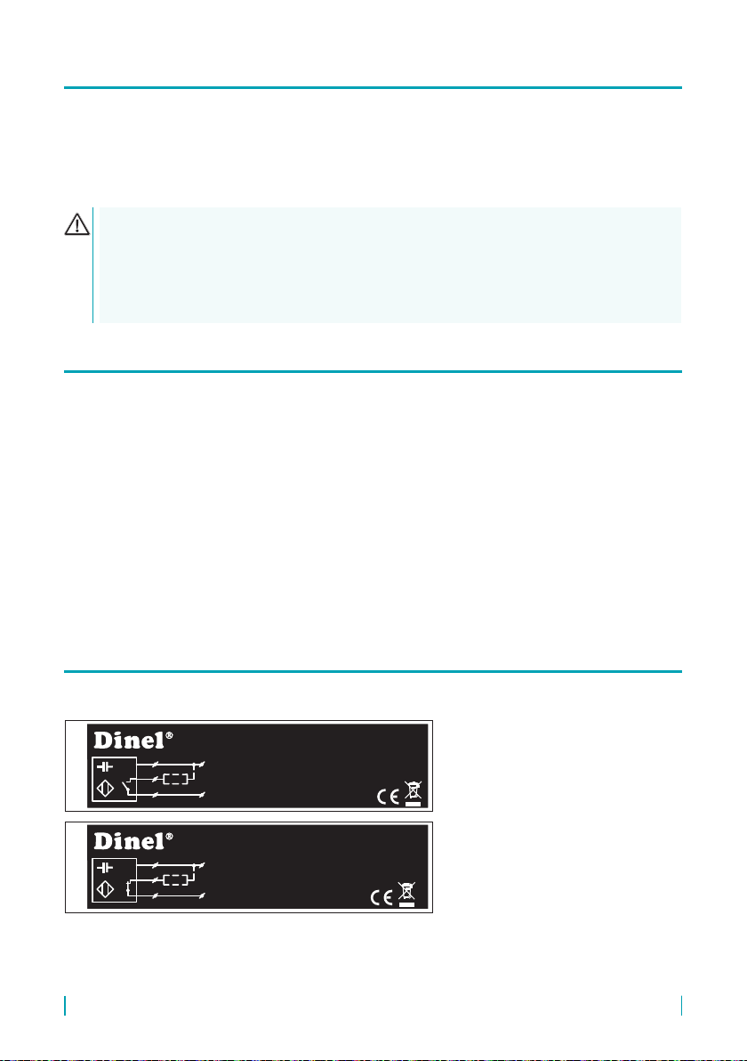
Labels for device of the type CPS-24N-_-NO, CPS-24N-_-NC, CPS-24N-_-PO, CPS-24N-_-PC:
ŠtítkyprovariantuCPS-24N-_-__
s
U
I
Iomax
n
s
U
I
Iomax
n
s
U
I
Iomax
n
0÷10mm
7 ÷ 36 VDC
3/7mA
200 mA
0÷10mm
7 ÷ 36 VDC
3/7mA
200 mA
0÷10mm
7 ÷ 36 VDC
3/7mA
200 mA
BN
BU
BK
+U
0V
BN
BU
BK
+U
0V
Dinel
BN
BU
BK
+U
0V
BN
BU
BK
+U
0V
s
U
I
Iomax
n0÷10mm
7 ÷ 36 VDC
3/7mA
200 mA
CPS-24N-_-NO No.: ______Cable: __ m
CPS-24N-_-NC No.: ______Cable: __ m
CPS-24N-_-PO No.: ______Cable: __ m
CPS-24N-_-PC No.: ______Cable: __ m
Dinel, s.r.o.
U Tescomy 249
760 01 Zlín
Czech Republic
www.dinel.cz
Dinel, s.r.o.
U Tescomy 249
760 01 Zlín
Czech Republic
www.dinel.cz
Dinel, s.r.o.
U Tescomy 249
760 01 Zlín
Czech Republic
www.dinel.cz
IP67
IP67
Dinel, s.r.o.
U Tescomy 249
760 01 Zlín
Czech Republic
www.dinel.cz
IP67
IP67
IP67
IP67
IP67
IP67

CPS–24 © Dinel, s.r.o.
11
Symbol of producer: logo Dinel®
Contact: Dinel, s.r.o., U Tescomy 249, 760 01 Zlín, Czech Republic, www.dinel.cz
Connection scheme and labelling of wires: +U, 0 V
Type of level meter: CPS-24N-_-NO, CPS-24N-_-NC, CPS-24N-_-PO, CPS-24N-_-PC
Cable length: Cable: _ _ m
Serial number: Ser. No.: ______ – (from the left: production year, serial production number)
sensitivity range of sensor Sn: 0-10 mm
Supply voltage range U: 7-36 V DC, Supply current I: 3 / 7 mA
Maximum output current Iomax: 200 mA
Coverage: IP6_
(Protection class according to electrical connection)
Compliance mark:
Electro-waste take-back system mark:
Labels for device of the type CPS-24Xi-_-R_:
Symbol of producer: logo Dinel®
Contact: Dinel, s.r.o., U Tescomy 249, 760 01 Zlín, Czech Republic, www.dinel.cz
Connection scheme and labelling of wires: +U, 0 V
Type of level meter: CPS-24Xi-_-R_
Cable length: Cable: _ _ m
Serial number: Ser. No.: ______ – (from the left: production year, serial production number)
Mark of non-explosive device: II 1 G Ex ia IIC T6 Ga
Limit parameters: Ui=12VDC, Ii=15mA, Pi=45mW, Ci=15nF, Li=10μH
Ambient temperature range : ta= -20 ... +70 °C , ta= -20 ... +60 °C (zone 0)
Number of certicate of intrinsic safety: FTZÚ 02 ATEX 0233X
Coverage: IP6_
(Protection class according to electrical connection)
Compliance mark: , No. of authorized person examining control of system quality: 1026
Electro-waste take-back system mark:
Size of labels 70 x 20 mm, the size shown does not correspond to reality.
ŠtítekprovariantuCPS-24Xi-_-__
II1GExiaIICT6Ga
U =12VDC I =15mA P=45mW
C =15nF t =-20...+70°C
t (zone 0)
iii
ia
ia
L =10uH =-20...+60°C
FTZÚ 02 ATEX 0233X
BN
BU
+U
0V
CPS-24Xi-_-R_ No.: ______Cable: __ m
1026
IP67
IP67
Dinel, s.r.o.
U Tescomy 249
760 01 Zlín
Czech Republic
www.dinel.cz
ŠtítkyprovariantuCPS-24N-_-__
s
U
I
Iomax
n
s
U
I
Iomax
n
s
U
I
Iomax
n
0÷10mm
7 ÷ 36 VDC
3/7mA
200 mA
0÷10mm
7 ÷ 36 VDC
3/7mA
200 mA
0÷10mm
7 ÷ 36 VDC
3/7mA
200 mA
BN
BU
BK
+U
0V
BN
BU
BK
+U
0V
Dinel
BN
BU
BK
+U
0V
BN
BU
BK
+U
0V
s
U
I
Iomax
n0÷10mm
7 ÷ 36 VDC
3/7mA
200 mA
CPS-24N-_-NO No.: ______Cable: __ m
CPS-24N-_-NC No.: ______Cable: __ m
CPS-24N-_-PO No.: ______Cable: __ m
CPS-24N-_-PC No.: ______Cable: __ m
Dinel, s.r.o.
U Tescomy 249
760 01 Zlín
Czech Republic
www.dinel.cz
Dinel, s.r.o.
U Tescomy 249
760 01 Zlín
Czech Republic
www.dinel.cz
Dinel, s.r.o.
U Tescomy 249
760 01 Zlín
Czech Republic
www.dinel.cz
IP67
IP67
Dinel, s.r.o.
U Tescomy 249
760 01 Zlín
Czech Republic
www.dinel.cz
IP67
IP67
IP67
IP67
IP67
IP67

12
© Dinel, s.r.o. CPS–24
Supply voltage 7 ... 36 V DC *
Current supply (state OFF / ON) 3 / 6 mA *
Switching current (NPN, PNP output) 200 mA *
Electric strength 500 V AC
Coupling capacity 2.2 nF
Max. switching frequency 5 Hz
Sensitivity – sensing distance 0 ... 10 mm (adjustable)
Hysteresis 5 ... 15 %
Ambient temperature range -20 ... +70°C
Protection class IP67
Cable (version with cable outlets) CPS – 24N
CPS –24Xi
PVC 3 x 0.5 mm2
PVC 2 x 0.75 mm2
Weight (incl. 2 m cable) Approx. 0.3 kg
* Only for variants “N”
variant Xi
Supply voltage 8 ... 9 V DC (Max. 12 V DC)
Current supply (state OFF / ON) – NAMUR ≤ 1 mA / ≥ 2.2 mA
Max. internal values Ui
= 12 V DC; Ii
= 15 mA; Pi = 45 mW; Ci = 15 nF; Li
= 10 µH
Part of the sensor Material
Housing St. steel W.Nr. 1.4301
Sensing surface PTFE
Ending St. steel W.Nr. 1.4301
Cable outlet (Variant “A”) Plastic POM
Cable outlet (Variant “B”) St. steel W.Nr. 1.4301
Output Variants
NPN (“NC”, “NO”) N
PNP (“PC”, “PO”) N
NAMUR (“RC”, “RO”) Xi
(EN 60079-0, EN 60079-10-1(2))
CPS–24N
Basic performance for non-explosive atmospheres.
CPS–24Xi
Intrinsically safe explosion-proof performance for use in hazardous areas (explosive gas
atmospheres or explosive atmospheres with dust), II 1G Ex ia IIC T6 Ga with intrinsi-
cally safe supply units, whole sensor zone 0.

CPS–24 © Dinel, s.r.o.
13
The device CPS–24 is packaged in a polyethylene bag, and the entire consignment is placed into
a cardboard box. A suitable ller material is used in the cardboard box to prevent mechanical damage
during transport. Remove the device from the packaging only just before using, thereby protecting it
from potential damage.
A forwarding company will be used to ship goods to the customer. Upon prior agreement, ordered
goods can be picked up in person at company headquarters. When receiving, please check to see
that the consignment is complete and matches the order, or to see if any damage has occurred to
the packaging and device during transport. Do not use a device clearly damaged during transport,
but rather contact the manufacturer in order to resolve the situation.
If the device is to be further shipped, it must be wrapped in its original packaging and protected
against impact and weather conditions.
Store the device in its original packaging in dry areas covered from weather conditions, with humidity
of up to 85 % without eects of chemically active substances. The storage temperature range is
-10 °C to +50 °C.
Dinel, s.r.o.
U Tescomy 249
760 01 Zlín
Czech Republic
Phone: +420 577 002 002
Fax: +420 577 002 007
E-mail: [email protected]
www.dinel.cz
Find the updated version at www.dinel.cz
version: 08/2017
industrial electronics
10/2017
This manual suits for next models
1
Table of contents
Other Dinel Switch manuals


Popular Switch manuals by other brands


Vivotek
Vivotek AW-FGT-100C-120 Quick installation guide

Comtrend Corporation
Comtrend Corporation GS-7316 Quick installation guide

Speaka Professional
Speaka Professional SP-HSW-231 operating instructions

LevelOne
LevelOne Infinity IES-1085 Quick installation guide

LevelOne
LevelOne GES-0852 Quick installation guide

TRENDnet
TRENDnet TPE-224WS - Web Smart PoE Switch Quick installation guide


