Dinel Flexi Watch FLD-32 User manual

Thru-wall level swiTch
FlD-32 "Flexi WaTch"
Before the rst use of the level sensor, read the instructions in this manual and keep it carefully.
The manufacturer reserves the right to do alteration without prior notice.
INSTRUCTION MANUAL


1. Basic description ........................................................................................................................... 4
2. Technical specications ................................................................................................................ 4
3. Dimensional drawings .................................................................................................................. 4
4. Recommended range of application .......................................................................................... 5
5. Unsuitable range of application .................................................................................................. 5
6. Installation and setup of the sensor ........................................................................................... 5
7. Electrical connection ..................................................................................................................... 6
8. Sensor setup .................................................................................................................................. 7
9. Fault indication .............................................................................................................................. 8
10. Connecting the FLD-32 to the analytical units ......................................................................... 9
11. Order code .................................................................................................................................13
12. Correct specication examples ...............................................................................................13
13. Accessories ................................................................................................................................13
14. Protection, safety, compatibility .............................................................................................13
CONTENTS
FLD-32 © Dinel, s.r.o.
4
To ensure maximum safety of control processes, we have dened the following safety instructions
and information. Each instruction is labelled with the appropriate pictogram.
Alert, warning, danger
This symbol informs you about particularly important instructions for installation and operation of
equipment or dangerous situations that may occur during the installation and operation. Not observing
these instructions may cause disturbance, damage or destruction of equipment or may cause injury.
Information
This symbol indicates particularly important characteristics of the device.
Note
This symbol indicates helpful additional information.
Used symbols
Thru-wall level switch FLD–32 "Flexi Watch" is designed for indication of the presence of
(conductive or non-conductive) liquids through the wall of glass or plastic vessels. The sensitivity
and switching mode can be simply set up using "programming" wire or magnetic pen, depending
on the type of sensor used. The sensor housing is made of a exible polyurethane material with
a self-adhesive layer and holes for fastening bands.
1 . BaSiC dESCripTiON
TEChNiCal SpECifiCaTiONS
Supply voltage 6 ... 30 V DC
Current consumption (idle-circuit condition) max. 0.6 mA
Switched current (min. / max.) 3.3 / 40 mA
Residual voltage in the closed state max. 6 V
Max. switching frequency 1 Hz
Ambient temperature range -20 ... +70 °C
Diameter of the vessel for the attachment of the sensor min. 300 mm
maximum thickness
of the vessel wall
conductive liquids
non-conductive liquids with Ɛr< 10*
8 mm
3 mm
Protection class IP 67
Housing material polyurethane
Type of connection cable PUR 3 x 0.14 mm2
Weight (including 2 m cable) about 40 g
Weight (without cable) 10 g
2 . TEChNiCal SpECifiCaTiONS
5
© Dinel, s.r.o. FLD-32
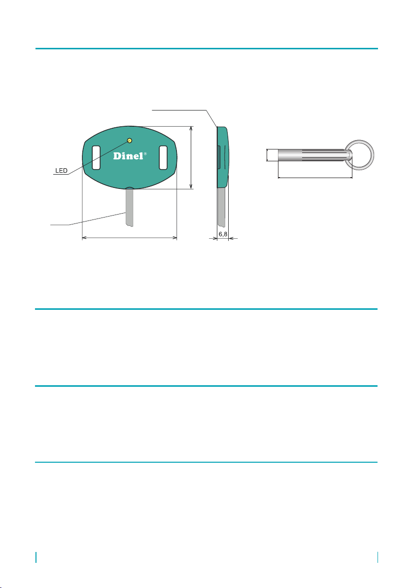
3 . dimENSiONal drawiNgS
32
48
min. ø 300
sensor
tank wall
self-adhesive layer
cable
50
8
magnetic pen MP-8
6 . iNSTallaTiON aNd SETup Of ThE SENSOr
Detection of various types of liquids - water, diesel fuel, oil, cooling uids, water solutions,
certain types of solvents. Suitable for plastic container tanks, plastic tubs, pools, canisters, etc.
The sensor is not intended for measurement of levels on level gauges and on the walls of
vessels with antistatic coating (partially conductive).
The sensor can be attached using self-adhesive layer or using special fastening bands.
Individual sensors may be arranged next to each other without any eect on their function.
4 . rECOmmENdEd raNgE Of appliCaTiON
5 . uNSuiTaBlE raNgE Of appliCaTiON

FLD-32 © Dinel, s.r.o.
6
FASTENING USING SELF-ADHESIVE LAYER
This technique may be used for at or slightly curved surfaces with a diameter larger than 300 mm.
1. One protective lm is removed from the adhesive layer and attached to the bottom of
the sensor.
2. The target area should be cleaned and degreased.
3. Remove the second protective lm and apply slight pressure to the sensor to attach it to
the desired location.
When replacing or removing the sensor, the sensor should be detached from the wall of the
tank carefully. If the original self-adhesive layer is destroyed, it needs to be removed from the
sensor and a new one should be used (delivered as accessories).
32
48
min. ø 300
sensor
tank wall
self-adhesive layer
cable
Fastening the FLD-32 using self-adhesive layer
fastening bands
with ø 180 - 300 mm
FASTENING USING ATTACHMENT BANDS
This technique is recommended for curved surfaces with a diameter of 180 - 300 mm. Use two
bands for fastening (each has one end modied).
1. The modied end of the band is threaded from the inside through the fastening eyelet
and glued over.
2. The same technique is used to attach the band at the second fastening eyelet.
3. The sensor is placed at the desired location on the tank, wrapping the bands around the
tank, tightening them and gluing over.
The sensor must be fastened well otherwise the function of the sensor may be unstable.
Fastening FLD-32 using attachment bands

7
© Dinel, s.r.o. FLD-32
7 . ElECTriCal CONNECTiON
BN
GN
WH
The positive pole of the power supply (+U) is connected to the brown wire, the negative (0V)
to the white wire. The output from the sensor is tted with short-circuit protection. Capacitive
loads and those with low resting resistance (light bulb) are evaluated by the sensor as a short-
circuit.
Note: In case of strong envi-
ronmental electromagnetic
interference, routing of wires
next to high-voltage lines or
when the total distance is
more than 30 m, the use of
a shielded cable is recom-
mended.
connecting the sensor with programming wire (version W)
BN
WH
Cable core
identication:
BN - brown
GN - green
WH - white
connecting the sensor without programming wire (version M)
The setup is made by using green wire (so-called programming) at version FLD-32N-W-S or
by touching the magnetic pen MP-8 at version FLD-32N-M-S to the sensitive spot on the body
of the sensor. This can be used to setup the upper and lower limits of liquid level, SO modes
(open contact when the level decreases) and SC (closed contact when the level decreases).
8 . SENSOr SETup
Attachment bands are recommended for applications where frequent removal of the sensor
from the vessel surface is expected.

FLD-32 © Dinel, s.r.o.
8
Setup using programming wire at version FLD-32N-W-S
SO mode: open when level decreases - For empty or partially lled vessel (level under the
lower edge of the sensor), the programming wire (P) is placed for about 2 seconds
on terminal 0V. Once the level reaches the upper edge of the sensor or when the
tank is full, the wire (P) is placed to +U terminal for the same time period (2 s).
SC mode: closed when level decreases - For empty or partially lled vessel (level under the
lower edge of the sensor), the programming wire (P) is placed for about 2 seconds
on terminal +U. Once the level reaches the upper edge of the sensor or when the
tank is full, the wire (P) is placed to 0V terminal for the same time period (2 s).
Note: The wire (P) is used only for programming the sensor. In all other situations it is
unconnected.
For comfortable setup of the FLD-32N-W-S sensor we recommend using of wall-mounted
evaluation unit Dinel, type SDSU-1222-W with setup buttons, power supply, optical status
indication and relay output.
Set up using magnetic pen MP-8 at version FLD-32N-M-S
The setup is made by using the magnetic pen MP-8 touching on a sensitive spot Mon the
front side of the sensor. Short touch (for 2 s max.) of the magnetic pen on the spot Mis used
to open the sensor, longer touch of the magnetic pen (for 4 s min.) closes the sensor. This is
used to set up the sensitivity to the measured medium and switching modes (SO, SC).
SO mode: open when the level decreases - For empty or partially lled vessel (level below
the lower edge of the sensor), touch the magnetic pen on the sensitive spot for 2 s
max. M (sensor opens). Once the tank is lled above the upper edge of the sensor,
touch the magnetic pen on the sensitive spot for 4 s at least M(sensor closes).
SC mode: closed when the level decreases - For empty or partially lled vessel (level below
the lower edge of the sensor, touch the magnetic pen on the sensitive spot for
4 s at least M (sensor closes). Once the tank is lled above the upper edge of
the sensor, touch the magnetic pen on the sensitive spot for 2 s max. M(sensor
opens).
9 . faulT iNdiCaTiON
* Thesensorwith"S"typeofoutput,witheachashofLED,closesforapprox.3ms.Thisisasucientlyshort
period to avoid unwanted contact making of the connected relay. For binary inputs, we recommend setting up the
ltrationsothatpulsesshorterthan3msarenotdetected.
**Setting of the close (open) limits to the same level or erroneous resolution between the "close" and "open" levels
(low medium permittivity).
control lamp function
orange LED
permanent shine – the sensor is closed
dark – the sensor is open
fast ashing (0.2 s interval) *– setup error **
slow ashing (0.8 s interval) – short-circuit at the output of the sensor.

9
© Dinel, s.r.o. FLD-32
10 . CONNECTiNg TO ThE aNalyTiCal uNiTS fld-32
Connecting of the sensor FLD-32 to the evaluation unit SDSU-1222-W
wh – white
bn –brown
gn – green
Legend:
Connecting of the sensor FLD-32
to the PLC logical unit
Connecting of the sensor FLD-32
to the relay coil
power
supply unit
power
supply unit
The thru-wall level switch FLD-32 "Flexi Watch" can be connected to various analytical units. See
below for connection examples of this setup. This provides general connection of the sensor
to the relay coil and to logical unit. Connection to specic analytical units is also described.
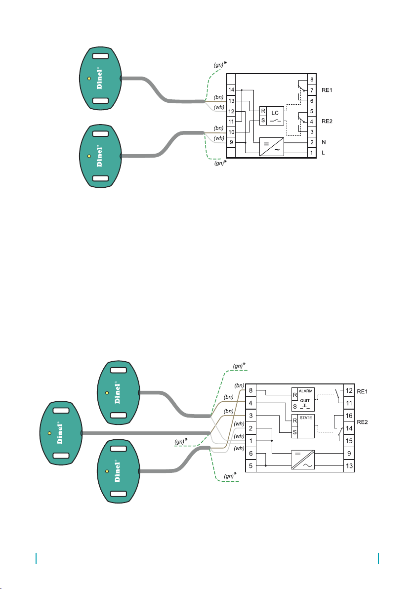
Connecting of the sensor FLD-32 to the evaluation units SDSU-1222-W and DSU-1222-W
This unit is intended for evaluation of sensors programmable using third wire (FLD-32 "Flexi
Watch"). It contains the programming buttons for setup of sensors and stabilized 12 V DC
power supply. It enables the level control (sensing of the amount of liquid in tanks, wells, etc.)
This unit is suitable for the FLD-32 variant with programming wire setup. DSU-1222-W unit is
suitable for the type with magnetic pen setup.
FLD-32 © Dinel, s.r.o.
10
Connecting of the sensor FLD-32 to the evaluation unit LCU-1232
Connecting of the sensor FLD-32 to the evaluation unit DSU-1222-W
230 AC
230 AC
Connecting of the sensor FLD-32 to the evaluation units LCU-1232 and LCU-1221
These units have two inputs to connect two operating sensors (MIN, MAX) and one input for
connection of an emergency sensor (ALARM - only LCU-1232). The operating sensors enable
the control of the operating relay (terminals 14, 15, 16). The emergency sensor controls the
emergency relay (terminals 11, 12).
11
© Dinel, s.r.o. FLD-32
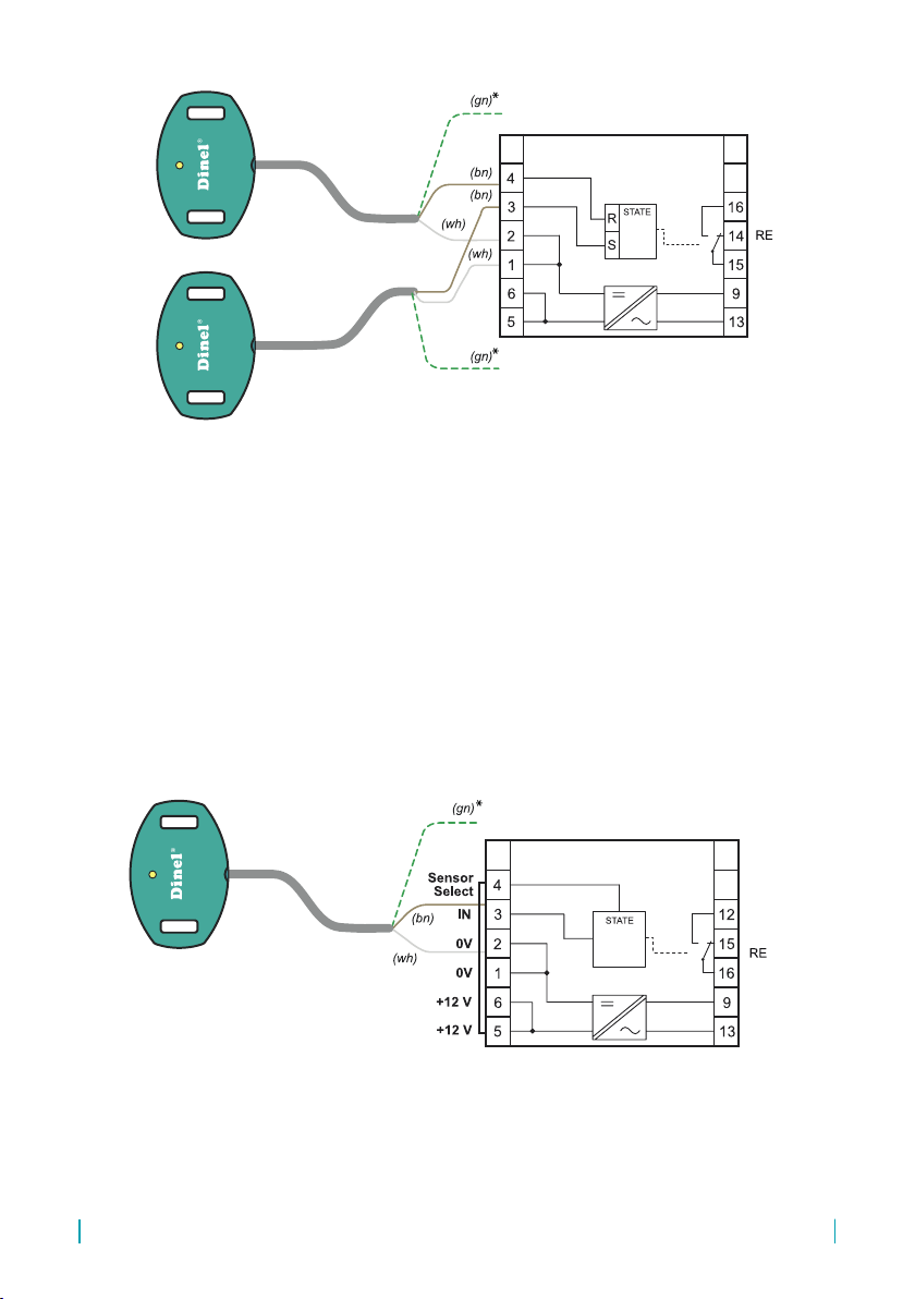
Connecting of the sensor FLD-32 to the evaluation units SSU-1211-W and DSU-1222-W
The unit SSU-1211 is used to connect a single sensor. It has one contact for the input signal
(terminal 3) and relay contact (12, 15, 16). To use the unit in combination with FLD-32, terminal
4 must be connected to terminal 5. The unit DSU-1222 is used to connect two sensors. It has
two contacts for the input signals (terminals 3 and 4) and relay contact (11, 12 and 15, 16).
Connecting of the sensor FLD-32 to the evaluation unit LCU-1221
Connecting of the sensor FLD-32 to the evaluation unit SSU-1211
230 AC
230 AC
230 AC
230 AC

FLD-32 © Dinel, s.r.o.
12
230 AC
Connecting of the sensor FLD-32 to the evaluation unit DSU-1222
position
of sensors
230 AC
230 AC
Connecting of the sensor FLD-32 to the evaluation unit TDU-1211
* Only for version FLD-32N-W-S.
Connecting of the sensor FLD-32 to the evaluation units TDU-1211
This unit has one input for connection of one limit sensor. The dened change of status on unit
input (terminal No.3 - IN) starts the timer in the range from 1 s to 100 min. While the timer is
running, the condition of the output relay changes (relay with switching contact) and contact is
made between terminals 12 and 16 (disconnected contact 15-16).
13
© Dinel, s.r.o. FLD-32
11 . OrdEr COdE
12 . COrrECT SpECifiCaTiON ExamplES
13 . aCCESSOriES
14 . prOTECTiON, SafETy, COmpaTiBiliTy
FLD – 32N-M-S K 2 FLD – 32N-W-S K 5
standard - included in the price of the sensor
• 2x two-sided adhesive layer
• 1x magnetic pen MP-8 (in case of version that uses MP-8 setup)
optional – for an extra charge
• attachment band (1 packaging - 2x 0.5 m)
• two-sided adhesive layer
The sensor is tted with the protection of supply voltage against polarity reversal, voltage
peaks and current overload.
Shock protection is provided by safe supply voltage according to HD 60364-4-41.
Electromagnetic compatibility is provided by compliance with standards EN 55022/B, EN
61326-1, EN 61000-4-2, -4-3, -4-4 and -4-6.
PRODUCT
FLD-32
PERFORMANCE
N non-explosive areas
SETUP TECHNIQUE
Mmagnetic pen
Wprogramming wire
TYPE OF OUTPUT
Selectronic switch
CABLE
Kcable length in m (2 or 5 m)
fld-32 N - w - S - K 2 availaBlE prOduCT alTErNaTivES

NOTES

Dinel, s. r. o.
U Tescomy 249
760 01 Zlín
Czech Republic
phone: +420 577 002 002
e-mail: [email protected]
www.dinel.cz
The current version of the manual can be found on www.dinel.cz
Version: 08/2017
07/2019
Table of contents
Other Dinel Switch manuals


Popular Switch manuals by other brands

Allied Telesis
Allied Telesis GS950 PS Series installation guide

Allied Telesis
Allied Telesis AT-9006T installation guide

CYP
CYP EL-8100V Operation manual

IBM
IBM 524 Quick installation guide

Guntermann & Drunck
Guntermann & Drunck TradeSwitch8-USB Installation and operation manual

Maiwe
Maiwe MIEN2016 user manual


