Dini Argeo TPWX2GDI Firmware update

ATEX SAFETY INSTRUCTION
TPWX2GD,TPWX2GDI,TPW20IEX2GD
TPWX_
05_17.12
_EN_U

TPWX2GD/TPWX2GDI/TPW20IEX2GD 2
INDEX
1. INTRODUCTION ................................................................................................................................................................. 3
2. SYMBOLS ........................................................................................................................................................................... 3
3. !! WARNINGS !! .................................................................................................................................................................. 4
4. DESCRIPTION OF THE SYSTEM ...................................................................................................................................... 6
5. SAFETY DATA / PLATE PARAMETERS ........................................................................................................................... 6
6. MARKINGS ......................................................................................................................................................................... 7
7. INSTRUCTIONS FOR INSTALLATION AND MAINTENANCE IN HAZARDOUS ZONE ................................................... 7
7.1 INSTALLATION EXAMPLE............................................................................................................................................ 8
8. DIMENSIONS (MM) ............................................................................................................................................................ 9
9. OPERATING INSTRUCTIONS ......................................................................................................................................... 10
10. REFERENCE DRAWINGS.............................................................................................................................................. 11
11. INSTRUMENT POWER SUPPLY ................................................................................................................................... 13
11.1 BATTERY CHARGING ............................................................................................................................................. 13
11.2 BATTERY CONNECTION TO RECHARGER AND WEIGHT INDICATOR .............................................................. 13
11.3 BATTERY INSTALLATION ....................................................................................................................................... 16
EU DECLARATION OF CONFORMITY ............................................................................................................................... 17
WARRANTY ......................................................................................................................................................................... 18

TPWX2GD/TPWX2GDI/TPW20IEX2GD 3
1. INTRODUCTION
In thanking you for purchasing this pallet truck scale, we would like you to take into consideration some aspects of this
manual:
this manual gives all the information for the correct functioning and maintenance of the
TPWX2GD/TPWX2GDI/TPW20IEX2GD pallet truck which is an integral part of the machine.
all the information given here is what is available at the time of printing; the manufacturer reserves the right to make
changes to the product at any time without prior notice. It is advisable to verify if there are any updates.
the person responsible for the use of the TPWX2GD/TPWX2GDI/TPW20IEX2GD pallet truck must make sure that all
the existing safety norms in the country of use are respected and guarantee that the instrument is used in conformity
with the use for which it has been manufactured for.
Some functions written in the sections regarding the weight indicator might not be available, because these depend on
the type of weighing system that has been purchased.
This pallet truck is designed for lifting and transporting loads put on a pallet or containers placed on flat, level surfaces with
adequate resistance.
It is also fitted with an electronic weighing system made up of a DFWATEX multifunction digital indicator put on the column
and of 4 load cells rigidly fixed inside the forks.
The metallic structure parts are electrically connected together and grounded through a sliding metallic chain. With the
TPWRAS option (antistatic driving wheels), the metallic structure is grounded through the sliding metallic chain and through
the antistatic wheels
2. SYMBOLS
Below are shown the symbols used:
- in the manual to recall the attention of the reader.
- on the instrument to recall the attention of the user
!!WARNING!! This operation must be made by specialized personnel
CE CONFORMITY
NOTES WHICH PARTICULARLY CONCERN THE USE OF THE INSTRUMENT IN A HAZARDOUS
AREA
"TECH.MAN.REF."
Means that
an advanced function is being described (therefore for the technical personnel) which will
be further explained in the corresponding technical manual.
The standards to which this manual refers are essential for its application. For dated standards, only the editions cited
apply. For undated standards, the latest editions apply (including any amendment).

TPWX2GD/TPWX2GDI/TPW20IEX2GD 4
3. !! WARNINGS !!
For weighing objects made up of light metals (aluminium, magnesium and titanium or their alloys, excluding the alloys
with less than 10% of aluminium, the varnishes and coatings with less than 25% of aluminium in weight), the use of
stainless steel forks is necessary.
The use of the instrument in hazardous areas require a special attention and special precautions during the use and
maintenance
The instrument conforms for use in zones having precise features: do not install and use the instrument in environments
different than those provided for.
The installation, maintenance and repair of the instrument, must be made by qualified and authorized personnel and
with the approval of expert technicians.
The safety of the explosion-proof system is guaranteed only if the system is installed, used and taken care of following
the instructions given in this manual and in the technical manual (TECH.MAN.REF.).
Check that the pallet truck scale is in good operating conditions.
Only spare parts approved by Dini Argeo should be used.
Be very careful when using the instrument; any sparks could cause an explosion.
Avoid accumulations of dust. To avoid dust layers, the user must regularly clean the surface of the enclosure,
considering that the maximum thickness allowed is < 5mm.
WARNING! ELECTROSTATIC HAZARD, CLEAN ONLY WITH WET CLOTHS OR ANTISTATIC PRODUCT
Avoid accumulations of electrostatic charges; therefore, when using the instrument in a hazardous zone, the appropriate
work clothing must be used by the operator or the maintenance person.
Do not cover the instrument with coverings made by materials which could have electrostatic charge
Do not paint the system
It is forbidden to modify or repair the instrument with components not conforming to the certification; this action
compromises the intrinsic safety of the instrument (with a subsequent loss of the Ex approval) and the nullification of
the product warranty.
It is forbidden to connect the instrument to modules not provided for by the certification; this action compromises the
intrinsic safety of the instrument (with a subsequent loss of the Ex approval). Contact Dini Argeo srl for further
information.
Avoid direct sunlight.
NEVER load the scale beyond the maximum capacity shown on the weight indicator’s plate.
Avoid the use of oxidising substances (hydrogen peroxide).

TPWX2GD/TPWX2GDI/TPW20IEX2GD 5
Use just the provided for battery; Contact Dini Argeo srl for further information.
Do not open, repair or modify a defective battery; this operation causes the loss of its intrinsic safety. Dispose of the
defective batteries.
The TPWX2GD atex pallet truck is an atex assembly composed of the TPW atex mechanical part, the DFWATEX2GD
atex weighing indicator and the atex load cell.
The TPWX2GDI/TPW20IEX2GD atex pallet truck is an atex assembly composed of the TPWX2GDI atex mechanical
part, the DFWATEX2GD atex weighing indicator and the atex load cell.
Read and follow also the atex manuals of the other parts: DFWATEX2GD atex weight indicator manual and the atex
load cell manual.
This scale has been designed to only weigh on pallets
Load only when forks are in the lowest position.
To get the best weighing results, lift up the forks (after loaded) about 5-10 cm.
It is not allowed to use the brake for slowing down, but only, and exclusively, for parking the already stopped pallet truck.
Check daily the status of the bearings and the bushings of the cart wheels and if there are problems such as frictions,
strange noises, overheating, offsetting of the wheels, etc., do not use the cart and contact the reseller for its repair.
The cart is grounded with a chain, check daily the presence of the grounding chain of the cart. Check daily that the chain
is clean, so that it can make the contact for the grounding of the Pallet truck. Do not remove the chain. The grounding of
the pallet truck is also possible by using Anti-Static wheels.
In case of approved scale, the weighing has to be done on a EUR-EPAL 800x1200mm pallet (ref. Norms UIC 435-2 and
UIC 435-4).
Contact Dini Argeo srl for further information.
For information on the operating mode of the weigh indicator DFWATEX, see the operating mode manual’s of the
indicator DFW downloadable from the website www.diniargeo.com.
This manual has been prepared with the maximum care, but any advice for improvements is most welcome.

TPWX2GD/TPWX2GDI/TPW20IEX2GD 6
FIX THE LOAD ON THE PALLET, AS SHOWN IN THE DRAWING
4. DESCRIPTION of the SYSTEM
The Atex assemblies TPWX2GD/TPWX2GDI/TPW20IEX2GD are devices for hazardous areas having presence of gas
and/or inflammable dust, designed and made according to the ATEX 2014/34/EU directive, group II category 2GD
according to the
IEC/EN 60079-0, IEC/EN 60079-11, IEC/EN 60079-31, EN 1127-1, EN 13463-1 and EN 13463-5. The protection mode of
the electronic weighing terminal (DFWATEX2GD) is Ex ib [ib Gb] IIC T4 and Ex tb [ib Db] IIIC T197°C IP65.
The weighing terminal is made up of a metallic case, which contains the various intrinsically safe electronic circuits:
DFWATEX2GD terminal, stand alone application with IP68 protection (TPWX2GD);
The weighing terminal is fitted with a CPU, LCD display, membrane keyboard and separate power supply unit, made up of
a Ni-MH battery or a power adapter, which has a separate ATEX certification.
The terminal provides for a connection to load cells (strain gauges – simple apparatus or intrinsically safe load cells, which
have a separate ATEX certification) / digital signals / electronic level - simple apparatus. A fibre optic connection for the
interfacing of devices in a safe zone is also provided for.
The metallic structure parts are electrically connected and a sliding chain is provided for its grounding.
5. SAFETY DATA / PLATE PARAMETERS
The power supply of the Atex assemblies TPWX2GD/TPWX2GDI/TPW20IEX2GD is provided with battery (See the
“DFWATEX2GD” atex weight indicator manual):
DFWBP76ATEX battery pack, Ni-MH, Vn = 9,6 V, 7600 mAh
Intrinsically safe circuits
See the “DFWATEX2GD” Atex weight indicator manual.

TPWX2GD/TPWX2GDI/TPW20IEX2GD 7
6. MARKINGS
TPWX2GD/TPWX2GDI /TPW20IEX2GD
The marking of the ATEX TPWX2GD/TPWX2GDI/TPW20IEX2GD whole system is:
II 2GD IIB T4 T197°C X
II
Group II (surface)
2
Category of the pallet truck
G
Explosive atmospheres caused by gas
D
Explosive atmospheres caused by dusts
IIB
Gas group
T4
Class of temperature of the pallet truck scale for gases,
T197°C
Maximum superficial temperature
of the
pallet truck scale
for dusts
X
The pallet truck whole is subject to special conditions for safe use specified in this manual
Hazardous zones
Category according to the
2014/34/EU
directive
Equipment protection level (EPL)
Gases
,
hazes
o
r
vapours
Zone 0
1G
Ga
Gases
,
hazes
or
vapours
Zone 1
2G or 1G
Gb or Ga
Gases
,
hazes
or
vapours
Zone 2
3G or 2G, 1G
Gc or Gb, Ga
Powders
Zone 20
1D
Da
Powders
Zone 21
2D or 1D
Db or Dc
Powders
Zone 22
3D or 2D, 1D
Dc or Db, Da
7. INSTRUCTIONS FOR INSTALLATION AND MAINTENANCE
IN HAZARDOUS ZONE
The Atex assemblies TPWX2GD/TPWX2GDI/TPW20IEX2GD must be installed and maintained according to the applicable
standards regarding the installations and maintenance in hazardous areas (different from the mines) classified for the
presence of gas as ZONE 1, and/or the presence of dusts like ZONE 21, for example: EN 60079-14 / IEC 60079-14, EN
60079-17 / IEC 60079-17, EN 1127-1 and all the standards applicable in the zone and in the installation environment.
Regarding the Atex protection type of the whole’s elements, please refer to the relative manuals. The installation and
maintenance must be executed in reference to the modes of protection “Ex i”, “Ex d” and “Ex t”.
DFWBP76ATEX battery pack: substitute only with battery pack of the same type. The RECHARGE must be made only
in SAFE ZONE and just with the DFWBPAL recharge device.
The indicator is grounded through a chain. Do not remove the chain
WARNING! :
The maintenance must be made after removing the voltage/power supply of the instrument.

TPWX2GD/TPWX2GDI/TPW20IEX2GD 8
7.1 INSTALLATION EXAMPLE
WE DECLINE ALL RESPO
NSIBILITY FOR DAMAGE
S CAUSED BY THE
UNOBSERVANCE OF THESE WARNINGS

TPWX2GD/TPWX2GDI/TPW20IEX2GD 9
PALLET
TRUCK
8. DIMENSIONS (mm)
1190
1150

TPWX2GD/TPWX2GDI/TPW20IEX2GD 10
9. OPERATING INSTRUCTIONS
A pallet truck scale is an electronic weighing system directly installed on a pallet truck.
Must be used on even solid surfaces and driven always in the normal position.
Before loading, check the maximum load allowed by the pallet truck scale in use.
( refer to instruction plate X on the side of the pallet truck – reference drawing B ).
The rudder has a double function, direction control and hydraulic lifting.
N.B. Lift up or pull down only when the pallet truck scale is in a standing still position.
N.B. Load only when forks are in the lowest position.
CONTROLS
The lever on the right side of the rudder can be put in 3 positions, like it shows on the plate “Y” in figure B.
POS. 1 – centre = TRANSPORT The rudder is completely free to allow driving control.
POS. 2 – down = LIFT UP By moving the lever downward the lifting mechanism is activated.
Pushing down the rudder will cause the load to lift up.
POS. 3 – up = PULL DOWN By moving the lever upward the load will descend. When the lever is
quickly moved upward, a special valve controls the descending speed of the load.
RUDDER ASSEMBLY (figure C)
1. Lock rudder ( 228 ) to hydraulic pump ( 200 ) with screws ( 27 ) that you can find in the box.
2. Lock chain ( 208 ) to lift down pedal ( 50 ). Rotate pedal to simplify the connection.
DESCENDING SPEED REGULATION (figure C)
1. Lift up forks to maximum height.
2. Set right lever to POS. 1 ( centre ).
3. Make sure the rudder ( 200 ) is in a vertical position.
4. Unscrew bolt ( 2 ) and turn clockwise the adjustable screw ( 48 ) until the forks start to descend.
5. Turn adjustable screw 1 ½ turn counter clockwise, then screw bolt ( 2 ).
6. You should be able to obtain a descending movement from every position of the rudder.
PARKING BRAKE (OPTIONAL)
If provided for, the rear wheel brake system can be fitted with a parking brake.
CAREFUL: use the brake only for parking the pallet truck and not to slow it down.
MAINTENANCE WARNINGS
Before you perform any service, make sure the pallet truck is in a condition of safety.
Never discharge any residue without taking the necessary environmental precautions.
Only perform the service described in this manual. Maintenance and repair jobs not included in this manual must be
performed by authorised personnel only.
Serious injury could result from service or maintenance performed by unqualified personnel.
Never alter the safety level of the machine. Always use identical replacement parts.
Never remove or hide in anyway instruction plates and stickers.
Do not modify the pallet truck.
Do not use inflammable cleaners. Do not use direct jets of water. Do not pour liquids on the indicator.
OIL LEVEL ( figure D )
Check oil level every 6 months. Only use hydraulic oil. No engine oil or brake oil.
Oil viscosity 30 Cst at 40°C . Quantity 0.3 lt.
With the fork in the lower position follow these steps:
1. Remove cover ( 204 ), o-ring ( 11 ) and cap ( 202 ).
2. If necessary add oil. Maximum filling level is 200mm below top of tank.
3. Turn on the pump to get air out of the hydraulic circuit.
4. Put cap ( 202 ), o-ring ( 11 ) and cover (204 ) back.

TPWX2GD/TPWX2GDI/TPW20IEX2GD 11
DAILY MAINTENANCE
To keep the pallet truck scale in good operating condition, the operator must perform daily these checkpoints:
Check overall conditions.
Check weighing scale.
Check printer ( if installed ).
Check pump.
Check rollers and wheels.
SCHEDULED MAINTENANCE (MAINTENANCE PERFORMED BY QUALIFIED PERSONNEL ONLY)
Please find below the programmed mainenance operations to be made by specialised personnel. Remember that before
starting the maintenanc one should place the cart on a flat surface.
Make sure to put the pallet truck scale on a flat and solid surface.
Check that nothing is blocking the rollers.
Grease rollers and wheels bearings: the lubrication with lithium grease is foreseen for every 6 months.
Grease control lever on rudder.
Check oil every six months. Fill up if necessary with IP46 hydraulic oil.
N.B. If oil needs to be replaced, follow the necessary precaution and law requirements for the disposal of the
exhausted oil.
Replace rollers and wheels when necessary.
The foreseen life of the bearings is the following:
- For applications with a single roller: 900 hours of use;
- For applications with double roller: 9000 hours of use;
Once reached this time period one should substitute these with bearing of the same model (SKF6204Z).
For any questions or problems check with an Authorised service Centre.
10. REFERENCE DRAWINGS
120
1150

TPWX2GD/TPWX2GDI/TPW20IEX2GD 12
C"
D"
LUBRIFICATION POINTS
Ref. “K” fig. D needs silicon oil for food industry, expiry of 1 month.
Ref. “P” fig. D needs silicon grease for food industry, expiry of 2 months.

TPWX2GD/TPWX2GDI/TPW20IEX2GD 13
11. INSTRUMENT POWER SUPPLY
The instrument is powered with a NiMH rechargeable battery, certified together with the indicator.
SPECIFICATIONS:
Nominal voltage
9,6
Vdc
Overall nominal capacity
7
,6 Ah
Maximum current in
output
120 mA
Battery operating time
from 60 hou
rs (maximum configuration) to 16
0 hours (minimum configuration)
Recharge time
15
–
18
hours (only with appropriate battery charger)
NOTE: we advise to completely recharge the battery before installing the instrument; if the instrument is not used for
a period longer than 30 days, WE ADVISE to disconnect the battery in order to avoid a progressive deterioration.
Do not connect other devices to the same socket.
Do not tread on the power supply cable.
11.1 BATTERY CHARGING
See the DFWATEX2GD atex weight indicator manual.
11.2 BATTERY CONNECTION TO RECHARGER AND WEIGHT INDICATOR
Models equipped with battery also include its recharger. Both
parts must be connected with their specific cables.
The two connectors have specific holes for a solid connection.
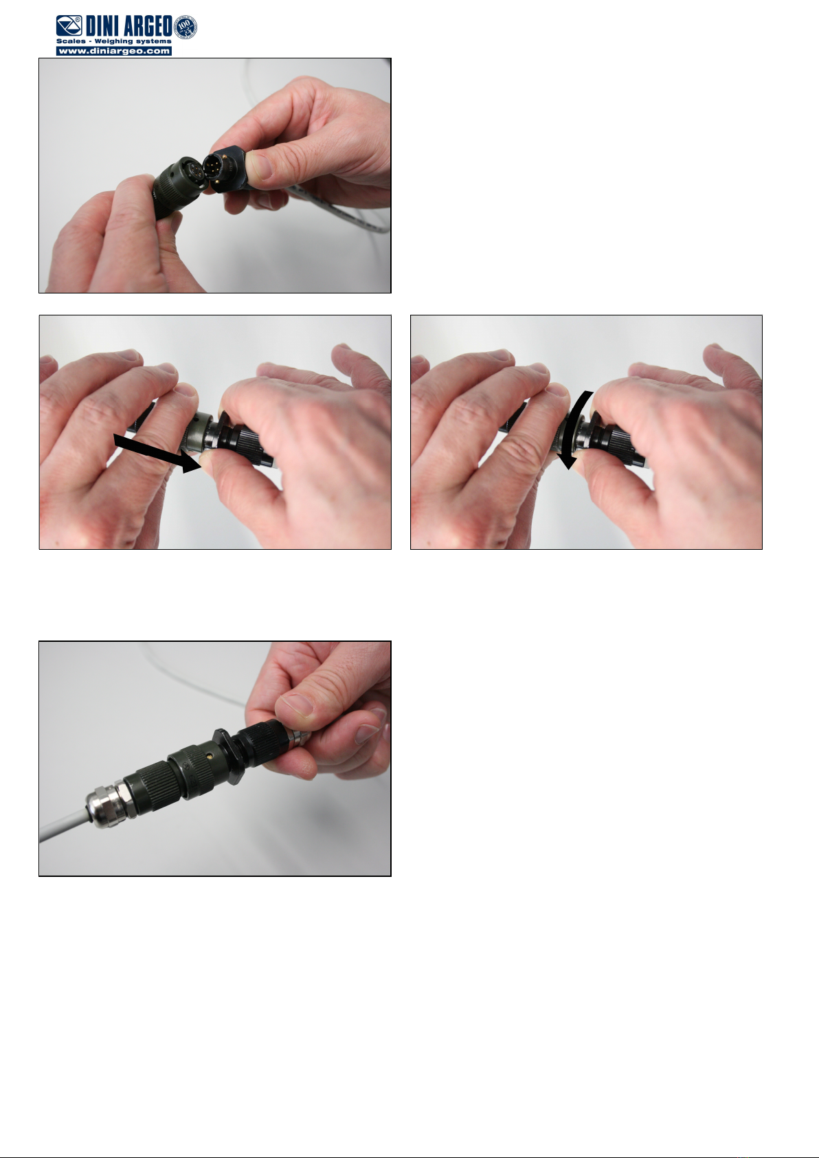
TPWX2GD/TPWX2GDI/TPW20IEX2GD 14
Connect the two cables, paying attention to their slots.
Grasp the cable terminal of the battery charger – or of the indicator – exactly in the point corresponding to its square
section. Push the battery cable connector, and then turn its rotating part in the sense indicated by the arrow, until the two
connectors are perfectly fitted.
The connection is now done.

TPWX2GD/TPWX2GDI/TPW20IEX2GD 15
To disconnect the cables, unscrew the rotating part following the sense indicated by the arrow, grasping the battery charger
terminal exactly in its square section. Pull the battery cable as shown in the figure.
Absolutely AVOID carrying out the connection / disconnection
of the cables grasping them in their external parts: there can
be the risk of breaking the internal wires.

TPWX2GD/TPWX2GDI/TPW20IEX2GD 16
11.3 BATTERY INSTALLATION
To remove the battery from the column one should:
1) turn and loosen the battery stops indicated in the figure
2) remove the battery connector from the power supply cable
To install the battery in the column one should:
1) connect the battery connector to the power supply cable
2) install and turn the battery stops indicated in the figure
NOTE: the battery DFWBP76ATEX can be connected and disconnected in explosion risk zones (ATEX ZONES).

TPWX2GD/TPWX2GDI/TPW20IEX2GD 17
EU DECLARATION OF CONFORMITY
We
DINI ARGEO Srl,
Via della Fisica, 20
41042 Spezzano di Fiorano - MODENA
Declare under our responsability that the products TPWX2GD/TPW2GDI/TPW20IEX2GD is made up of:
DFWATEX2GD series electronic weighing terminal (CEC 07 ATEX 060 rev2 CE type certificate nr.)
2GD series TPW pallet truck scale (Tech. File AETF01 Dep. n° CEC-04/2036-ADF088)
Dini Argeo atex load cells (CEC 07 ATEX 093 X rev2 CE type certificate nr.)
TPWRAS Antistatic driving wheels (optional)
Described in this declaration conform to the following directives:
- EMC 2014/30/EU Directive
- ATEX 2014/34/EU Directive
- 2014/31/EU Directive (MODULE B: EN 45501 / 1998 – MODULE D: EN 45501 / 2015) (*)
The conformity is confirmed by the observance of the following international standards:
IEC 60079
-
0:2011
+IS1:2013
/ EN 60079
-
0:2012
+A11:2013
IEC 60079-11:2011 / EN 60079-11:2012
IEC 60079-31:2013 / EN 60079-31:2014
EN 1127-1:2011
EN 13463-1:2009
EN 13463-5:2011
EN 61000
-
6
-
2:2006, EN 61000
-
6
-
4:2007
+A1:2011
,
EN 61326-1:2013, EN 55011:2009+A1:2010
(*) if "M" mark is applied.
Marking:
- II 2GD IIB T4 T197°C X
Spezzano di Fiorano, 04/12/2017
Signature
Marco Bertoni
President

TPWX2GD/TPWX2GDI/TPW20IEX2GD 18
WARRANTY
The TWO YEARS warranty period begins on the day the instrument is delivered. It
includes spare parts and labour repair at no charge if the INSTRUMENT IS
RETURNED prepaid to the DEALER’S PLACE OF BUSINESS. Warranty covers all
defects NOT attributable to the Customer (so are not included in the warranty,
failures resulting from improper use) and NOT caused during transport.
If on site service is requested (or necessary), for any reason, where the instrument
is used, the Customer will pay for all of the service technician’s costs: travel time
and expenses plus room and board (if any).
the Customer pays for the transport costs (both ways), if the instrument is shipped to
DEALER or manufacturer for repair.
The WARRANTY is VOIDED if any of the following occurs: repairs or attempted
repairs are made by unauthorised personnel, connected to equipment installed by
others, or is incorrectly connected to the power supply, or instrument has defects or
damage due to carelessness or failure to follow the guidelines in this instruction
manual.
This warranty DOES NOT provide for any compensation for losses or damages
incurred by the Customer due to complete or partial failure of instruments, even
during the warranty period.
AUTHORIZED SERVICE CENTRE STAMP
This manual suits for next models
2
Table of contents
Other Dini Argeo Forklift manuals


